1
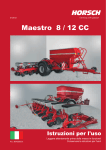
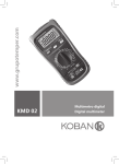
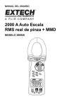
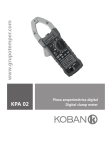
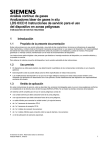
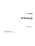
Product / Producto: PROFFESIONAL
MULTIMETER WITH AUTO-RANGE /
MULTIMETRO PROFESIONAL CON
AUTO RANGO
Model / Modelo: MUL-285
Brand / Marca: Steren
Call Center / Centro de Atención a Clientes
del Interior 01 800 500 9000
Mexico City / Cd. de México: 53 54 22 90
Warranty
This Steren product is warranted under
normal usage against defects in
workmanship and materials to the original
purchaser for one year from the date of
purchase.
Póliza de Garantía
Garantiza este producto por el término de
un año en todas sus partes y mano de obra
contra cualquier defecto de fabricación y
funcionamiento, a partir de la fecha de
entrega.
CONDITIONS:
1. This warranty card with all the required information, the invoice or purchase ticket, the product box or package, and the product, must be presented with the product
when warranty service is required.
2. If the product stills on the warranty time, the company will repair it free of charge even the transportation charges.
3. The repairing time will not exceed 30 natural days, from the day the claim was received.
4. Steren sells parts, components, consumables and accessories to customer, as well as warranty service, at any of the following addresses:
THIS WARRANTY IS VOID ON THE NEXT CASES:
If the product has been damage by an accident, acts of God, mishandling, leaky batteries, failure to follow enclosed instructions, improper repair by unauthorized
personal, improper safe keeping or otherwise.
Notes:
a) The customer can also claim the warranty service on the purchase establishment.
b) If you lose the warranty card, we can reissue it just showing the invoice or purchase ticket.
CONDICIONES
1. Para hacer efectiva esta garantía se requiere: La presentación de esta póliza y del producto, en el lugar en donde fue adquirido o en ELECTRONICA STEREN S.A. DE C.V.
2. ELECTRONICA STEREN S.A. DE C.V. se compromete a reparar el producto en caso de estar defectuoso sin ningún cargo al consumidor. Los gastos de transportación
serán cubiertos por el proveedor.
3. El tiempo de reparación en ningún caso será mayor a 30 días contados a partir de la recepción del producto en cualquiera de los sitios en donde pueda hacerse efectiva la
garantía.
4. El lugar donde puede adquirir partes, componentes, consumibles y accesorios, así como hacer válida esta garantía es: En cualquiera de las direcciones arriba mencionadas.
ESTA GARANTIA NO ES VALIDA EN LOS SIGUIENTES CASOS:
1. Cuando el producto ha sido utilizado en condiciones distintas a las normales.
2. Cuando el producto no ha sido operado de acuerdo con el instructivo de uso.
3. Cuando el producto ha sido alterado o reparado por personas no autorizadas por ELECTRONICA STEREN S.A. DE C.V.
Nota: El consumidor podrá solicitar que se haga efectiva la garantía ante la propia casa comercial, donde adquirió el producto. Si la presente garantía se extraviara, el
consumidor puede recurrir a su proovedor para que le expida otra póliza de garantía, previa presentación de la nota de compra o factura respectiva.
DATOS DEL DISTRIBUIDOR
DISTRIBUTION / NOMBRE / DISTRIBUIDOR:
ADDRESS / DOMICILIO:
PRODUCT / PRODUCTO:
MODEL / MODELO:
BRAND / MARCA:
SERIAL NUMBER / No. DE SERIE:
DATE OF DELIVERY / FECHA DE ENTREGA:
V1206
INSTRUCTIVO DE USO DE MULTIMETRO PROFESIONAL CON AUTO
RANGO
INSTRUCTION MANUAL FOR PROFFESIONAL MULTIMETER WITH
AUTO-RANGE
Modelo: MUL-285
Marca: Steren
Model: MUL-285
Brand: Steren
Antes de utilizar su nuevo Multímetro Profesional con auto rango lea
este instructivo para evitar cualquier mal funcionamiento. Guárdelo
para futuras referencias.
Before using your new Proffesional Multimeter With Auto-Range,
please read this instruction manual to prevent any damage. Put it
away in a safe place for future references.
Su nuevo equipo está diseñado para ser usado por ingenieros, técnicos y
aficionados, quienes demandan un instrumento que sea preciso, seguro,
portátil y siempre listo para ser usado. Cada una de las posiciones de
prueba es rápida y fácilmente seleccionada con un simple giro del
interruptor selector.
Your new STEREN multimeter is designed for use by engineers,
technicians, and all those who demand a device which is highly accurate,
safe, portable, and easily used. Every testing position quickly and easily
selected with a simple turn of the dial.
IMPORTANTE
Para evitar un choque eléctrico o daños al multímetro, no lo utilice cerca
de sitios mojados.
Retire las puntas de medición antes de retirar la cubierta.
Periódicamente limpie la cubierta con un paño suave y húmedo. No utilice
líquidos abrasivos o solventes.
Antes de abrir la cubierta, asegúrese de que las puntas de prueba no
estén conectadas a ningún circuito.
Si utiliza este equipo en un ambiente con una fuerte radio frecuencia
electromagnética, podría influir en la precisión de las mediciones.
IMPORTANT
In order to avoid an electrical shock or damage to the multimeter, do not
use it in wet areas.
Remember to periodically clean the testing points with a soft dry rag. Do
not use any liquids, abrasives, or solvents in order to clean the testing
points.
Before opening the multimeter’s cover, make sure that the testing points
are not connected to any circuit.
If this multimeter is used in areas with a high electromagnetic radio
frequency, this frequency could influence your readings.
INSTRUCCIONES GENERALES
Este instrumento cumple con los estándares de sobre voltaje IEC 1010-1
(61010-1 @ IEC: 2001), CAT. II 1000V y CAT. III 600V
General Instructions
This device complies with voltage standards set by IEC 1010-1 (61010-1
@ IEC: 2001), CAT. II 100V, and CAT. III 600V
MEDIDAS DE SEGURIDAD
Si el multímetro es utilizado cerca de equipo que genere ruido, la pantalla
podría volverse inestable o indicar errores.
No utilice el multímetro o las puntas de prueba si se encuentran dañadas.
Utilice el multímetro únicamente como se indica en este manual.
Tenga extrema precaución cuando utilice el equipo cerca de conductores
sin aislar.
No opere el equipo cerca de polvo, vapor, o gas.
Verifique la operación del multímetro realizando una medición con un
voltaje conocido.
Cuando el valor del rango a medir es desconocido, compruebe que el
rango inicial ha sido predeterminado en el nivel más alto, o de ser posible,
elija la opción de autorango.
Para evitar daños, no exceda el límite máximo de los valores de entrada
mostrados en las tablas de especificaciones.
Cuando el multímetro esté conectado a circuitos de medición, no toque las
terminales sin usar.
Tenga cuidado cuando trabaje con voltajes por arriba de 60Vdc o 30Vac
rms. Estos voltajes pueden provocar un choque eléctrico.
Cuando realice conexiones, conecte la punta de medición común antes de
conectar la punta viva. Cuando las desconecte, primeramente quite la
punta viva y posteriormente la punta común.
Antes de cambiar la función del multímetro, desconecte las puntas del
circuito a medir.
Para todas las funciones con voltaje CD, para evitar el riesgo de un
choque eléctrico debido a lecturas inadecuadas, verifique la presencia de
cualquier voltaje CA primeramente. Posteriormente seleccione un rango
de voltaje de CD igual o mayor al registrado en el rango de CA.
Antes de insertar transistores para su medición, asegúrese de que las
puntas de medición han sido retiradas de cualquier circuito.
No conecte componentes a la entrada hFE cuando realice mediciones de
voltaje con las puntas de medición.
Desconecte circuitos de energía y descargue todos los capacitores de alto
voltaje antes de realizar mediciones con las puntas.
Nunca realice mediciones de resistencia o continuidad en circuitos vivos.
Antes de realizar medición de corriente, revise el fusible del multímetro y
retire cualquier corriente de energía del circuito.
Cuando realice mediciones en televisores que desee reparar, asegúrese
de utilizar un filtro de TV para atenuar los picos de energía que pueden
dañar el multímetro.
Reemplace la batería en cuanto aparezca un icono de batería en la
pantalla. Con batería baja, el multímetro podría producir lecturas falsas
que pueden ocasionar choques eléctricos o daños físicos.
Security Measures
If this multimeter is used near devices that generate a lot of noise, the
screen might become unstable or indicate errors.
Do not use the multimeter or the testing points if they are damaged.
Only use this multimeter as indicated in this instruction manual.
Make sure to take extreme precaution when using this multimeter near
un-isolated conductors
Do not operate this multimeter near dust, steam, or gas.
When the range of the value to be measured is unknown, make sure to
choose the highest range or use the auto-range mode.
In order to avoid damage, do not exceed the maximum values indicated in
the specification tables.
When the multimeter is connected to measurement circuits, do not touch
the terminals.
Take precaution when working wityh voltages above 60 VDC or 30 VAC
rms. These voltages could cause an electrical shock.
When making connections, connect the common testing point before
connecting the live testing point.
When disconnecting, disconnect the live point before disconnecting the
common testing point.
Before changing the multimeter’s function, make sure to disconnect the
testing points from the circuit being measured.
For all functions with DC voltage, in order to avoid the risk of electrical
shock due to inaccurate readings, verify the presence of any AC voltage.
Afterwards, select a DC voltage range equal to or higher to the registered
AC voltage.
Before inserting transistors for measurement, make sure the testing points
have been removed from any circuit.
Do not connect components to the hFE input when measuring voltage with
the testing points.
Disconnect energy circuits and discharge all high voltage capacitors
before making any measurements with the testing points.
Never make resistance or continuity measurements on live circuits.
Before measuring current, check the multimeter’s fuse and remove any
energy current from the circuit.
When making measurements on television you wish to repair, make sure
to use a TV filter in order to avoid the voltage spikes that can be caused
and damage your multimeter.
Make sure to replace the multimeter’s battery as soon as the low battery
indicator appears on the LCD screen. With low battery, the multimeter
may produce inaccurate readings which can cause electrical shock or
physical damage.
No realice mediciones de voltaje mayores a 600V en instalaciones de
categoría 3, o 1000V en categoría 2.
Do not make measurements above 600 V in category 3 installations or
1000 V in category 2.
SIMBOLOGÍA
Symbols
Precaución: refiérase al manual de instrucciones. El uso incorrecto
puede resultar en daños al equipo o sus componentes.
Precaution: Refer to the instruction manual. The incorrect use
may result in damage to the multimeter or its components.
Voltaje peligro puede estar presente.
Dangerous Voltage may be present.
CA (Corriente Alterna)
~
AC (Alternate Current)
CD (Corriente Directa)
DC (Direct Current)
Tierra
Ground
Doble aislamiento
Double Isolation
Fusible
Fuse
Conforme a directivas de la Unión Europea
Conforms to directives of the European Union
INSTRUCCIONES
Retire las puntas de medición antes de quitar la cubierta del multímetro o
el compartimiento de baterías.
Antes de abrir el equipo, asegúrese de desconectarlo de cualquier fuente
de corriente eléctrica, así como también de que no existe electricidad
estática, esto podría dañar componentes internos.
Recuerde que cuando el equipo está abierto, algunos capacitores internos
podrían contener energía que puede ser peligrosa, inclusive si el equipo
está apagado.
Cuando no vaya a utilizar el equipo por un tiempo prolongado, retire las
baterías y no lo almacene en lugares con temperatura alta o con alta
humedad.
Instructions
Remove the testing points before removing the multimeter’s cover or the
battery cover.
Before opening the device, make sure to disconnect it from any source of
electrical cvurrent. Also make sure that there is no static electricity
present, these could cause electrical shocks or damage internal
components.
Remember that when the device is open, some internal capacitors may
contain electrical energy that might be dangerous even when the device is
powered off.
When you will not be using this device for an extended period of time,
remove the batteries in order to conserve the battery life. Also, do not
sotore this device in wet or humid areas or areas with high temperatures.
CONTROLES
1.- Control de rango
2.- Botón de retención de datos
3.- Selector de CA, CD o
/
4.- Entrada para prueba de transistores
5.- Interruptor de función / encendido
6.- Entrada V / Ω / F / Cx
7.- Entrada COM
8.- Entrada mA /
9.- Entrada 10A
Controls
1. Range Control
2. Data retention button
3. AC, DC, or
/
selector.
4. Transistor test input.
5. Function and on/off switch
6. V / Ω / F / Cx Input
7. COM Input
8. mA /
Input
9. 10A Input
1
2
4
3
5
9
6
8
7
PANTALLA DE LCD
LCD Screen
AUTO
H
hFE
- +
DC
-8.8.8.8
~
AC
Símbolo / Symbol
kMΩHz
nцmFAV
Significado / Meaning
La batería tiene poca energía.
Advertencia: Asegúrese de cambiar la batería inmediatamente, ya que de lo contrario podría provocar
lecturas falsas, que pueden provocar choques eléctricos o daños personales.
- +
~
AC
DC
The battery has low energy
Warning: Make sure to change the battery immediately. Otherwise, the multimeter could produce inaccurate
readings which could cause electrical shocks or personal damages.
Indica lecturas negativas.
Indicates negative readings
Indicador de corriente o voltaje CA
Estos valores son mostrados como el promedio del valor absoluto de entrada, calibrada para indicar el
equivalente del valor rms de una onda sinoidal.
Indicator for AC voltage or current
These values are displayed as an average of the absolute value of the input. This is calibrated to indicate the
equivalent of the rms value of the sinoidal wave.
Indicador para voltaje CD o corriente
Indicator for DC voltage or current
PANTALLA DE LCD (Cont.)
LCD Screen (Cont.)
El multímetro se encuentra en modo automático, el multímetro seleccionará el rango con la mejor resolución.
AUTO
The multimeter is in automatic mode, the multimeter will select the range with the best resolution.
Indicador de Modo de Prueba de Diodo
Diode test mode indicator
hFE
Indicador de Modo de prueba de transistor
Transistor test indicator
Indicador de Modo de Continuidad
Continuity test indicator
H
Indicador de Modo de retención de datos
V:
mV:
Volts. Unidad de voltaje / Volts. Voltage unit.
Milivolt 1x10⁻³ p 0.001volts / Milivolt. 1 x 10⁻³ or 0.001 volts
A:
mA:
μA:
Amperes Unidad de corriente / Amps. Current unit
Miliamper 1x10⁻³ o 0.001 amperes / Miliamp. 1 x 10⁻³ or 0.0014 amps
Microamper 1x10⁻⁶ o 0.000001 amperes / Microamp. 1 x 10⁻⁶ or 0.000001 amps
Ω
kΩ
MΩ
Ohm. Unidad de resistencia / Ohm. Resistance unit.
Kilohm 1x10³ o 1000ohms / Kilohm. 1 x 10³ or 1,000 ohms
Megohm 1x10⁶ o 1,000,000 ohms / Megaohm. 1 x 10⁶ or 1,000,000 ohms
Hz
KHz
MHz
Hertz. Unidad de frecuencia en ciclos / segundo // Hertz. Frequency unit cycles/second
Kilohertz. 1x10³ o 1000 hertz / Kilohertz. 1 x 10³ or 1,000 hertz
Megahertz. 1x10⁶ o 1,000,000 hertz / Megahertz. 1 x 10⁶ or 1,000,000 hertz
Data retention mode indicator
F
μF
nF
Faradio. Unidad de capacitancia / Farad. Capacity unit
Microfaradio. 1x10⁻⁶ o 0.000001 faradios / Microfarad. 1 x 10⁻⁶ or 0.000001 farads
Nanofaradio. 1x10⁻⁹ 0 0.000000001 faradios / Nanofarad. 1 x 10⁻⁹ or 0.000000001 farads
OL
La entrada es demasiado larga para el rango seleccionado / The input is too long for the selected range.
Botones
Buttons
Botón / Key
Función / Function
~
A mA μA
Opción Power-up
Power up option
DATA-H
RANGO
RANGE
Cualquier posición del switch
Any switch position
V~
V
Ω
mA & μA
Operación / Operation
Interruptores entre la Prueba del Diodo y la revisión de Continuidad.
Switches between diode test and continuity
Interruptores entre CD y CA
Switches between DC and AC
Función de auto apagado
Auto-off function
Presione HOLD para entrar y salir del modo de Retención de Datos
Press HOLD in order to enter and exit data retention mode
1.- Presione RANGE para entrar al modo de selección de rango manual.
2.- Presione RANGE para pasar entre los diferentes rangos disponibles de la función
seleccionada.
3.- Presione RANGE y mantenga presionado por dos segundos para regresar al modo
de rango automático.
1.- Press RANGE in order to enter manual range selection mode.
2.- Press RANGE in order to switch between the different ranges available for the
selected function.
3.- Press RANGE and keep it pressed in order to return to auto-range mode.
INTERRUPTOR ROTATORIO
Rotary Dial
Posición / Position
V~
Función / Function
Medición de voltaje CA
AC voltage measurement
V
Medición de voltaje CD
DC voltage measurement
Ω
Medición de resistencia
Resistance measurement
Prueba de diodo / Revisión de continuidad
Diode test / continuity
Cap
Medición de capacitores
Capacitor measurement
Hz
Medición de frecuencia
Frequency measurement
hFE
Medición de transistores
Transistor measurement
Medición con gancho (opcional)
Hook measurement (optional)
μA
Medición de corriente CA o CD de 0.1μA a 4000μA
Current measurement AC or DC from 0.1 uA to 4000 uA
mA
Medición de corriente CA o CD de 0.01mA a 400mA
Current measurement AC or DC from 0.01 mA to 400 mA
A
Medición de corriente CA o CD de 0.01A a 10.00A
Current measurement AC or DC from 0.01 A to 10 A
TERMINALES
Terminals
Terminal
COM
Descripción / Description
Terminal de regreso para todas las mediciones (recibiendo la punta de
medición negra o el plug “com” del gancho opcional).
Return terminals for all measurements
VΩFCx
Entrada para mediciones de voltaje, resistencia, frecuencia, capacitores,
diodos y continuidad (recibiendo la punta de medición roja).
Input for voltage, resistance, frequency, capacitor, diode, and continuity
measurements. (Red testing point)
mA
Medición de entradas de corriente de 0.1μA a 400mA (recibiendo la punta de
medición roja o el plug “+” del gancho opcional.
Measurement for current inputs from 0.1uA to 400mA (Red testing point)
A
Mediciones de entrada de corriente de 400mA a 10A (recibiendo la punta de
medición roja).
Measurement for current inputs from 400 mA to 10 A (Red testing point)
DESCRIPCIÓN DE FUNCIONES
Function Description
Funciones generales
General Functions
Modo de retención de Datos
Esta función permite que el resultado obtenido se mantenga en pantalla.
Si activa la función de Retención de Datos mientras se encuentra en
modo de rango automático, hará que el multímetro cambie a modo de
selección de rango manual, pero la escala del rango se mantendrá igual.
Esta función puede ser cancelada cambiando el modo de medición,
presionando el botón de RANGE o presionando el botón de HOLD una
vez más.
Data retention mode
This function allows the result obtained from a measurement to stay on the
LCD screen. If you activate this function while in auto-range mode, the
multimeter will automatically switch to manual range mode but the range
will stay the same.
This function can be cancelled by changing the measurement mode,
pressing the RANGE button, or pressing the HOLD button again.
Para entrar y salir del modo de Retención de Datos:
1.- Presione el botón de Hold una vez. En pantalla aparece la letra H.
2.- Si presiona una vez más el botón de Hold, regresará al modo normal.
In order to enter and exit data retention mode:
1. Press the HOLD button once. The LCD screen will display “H”
2. If you press the HOLD button again, you will return to normal mode.
Selección de rango Manual y automático
En modo de selección de rango automático, el multímetro selecciona el
mejor rango de acuerdo a la entrada detectada. Esto permite que pueda
cambiar los puntos a medir, sin necesidad de ingresar un nuevo rango.
Selecting Auto-range and manual range mode
In auto-range mode, the multimeter will select the best range according to
the detected input. This allows you to change the points to be measured
without the need of changing the range.
En modo manual, puede seleccionar el rango. Esto permite que pueda
controlar manualmente el rango y mantenerlo fijo en el multímetro.
In manual mode, you can select the range. This allows you to manually
control the range and keep it set on the multimeter.
El multímetro se encuentra previamente activado en modo de rango
automático en mediciones que tienen más de un rango. Cuando se
encuentra en este modo, la palabra AUTO aparece en pantalla.
The multimeter was previously activated in auto-range mode that has
more than one range. When in this mode, the word “AUTO” will be
displayed on the LCD screen.
Para entrar y salir del modo manual de selección de rango:
1.- Presione RANGE. El multímetro entra al modo manual. La palabra
AUTO desaparece de la pantalla. Cada vez que presione RANGE, se
incrementará el rango. Cuando el nivel más alto es alcanzado, el
multímetro regresa al nivel más bajo.
In order to enter and exit manual range mode:
1. Press RANGE. The multimeter will enter manual range mode. The
word AUTO will disappear from the LCD screen. Every time you press
RANGE, the range will increase. When the highest range is reached, the
multimeter will return to the lowest range.
2.- Para salir del modo manual, presione RANGE y mantenga presionado
el botón por dos segundos. El multímetro regresará al modo automático, y
la palabra AUTO aparecerá en pantalla.
2. In order to exit manual range mode, press RANGE and hold it for 2
seconds. The multimeter will return to auto-range mode and “AUTO” will
appear on the LCD screen.
Nota:
Si cambia de forma manual el rango de medición después de entrar al
modo de Retención de Datos, el multímetro saldrá de este modo.
Note:
If you switch to manual range mode after entering data retention mode, the
multimeter will exit this mode.
AHORRO DE ENERGIA
El equipo entra en modo de ahorro de energía después de que no ha sido
utilizado por 30 minutos. Después de este tiempo la pantalla se apagará.
Energy Saving
The device will enter energy saving mode if it has not been used for 30
continuous minutes. After this time, the LCD screen will power off.
Presione HOLD o mueva la perilla rotatoria para regresar al modo activo.
Press HOLD or move the dial in order to return to active mode.
Para desactivar esta función, mantenga presionada la tecla
mientras enciende el multímetro.
In order to disactivate this function, keep the
when turning the multimeter on.
~
button pressed
~
FUNCIONES DE MEDICIÓN
Medición de voltaje CA y CD
Measurement Functions
Measuring AC and DC voltage
Para prevenir un choque eléctrico o daños en el equipo, no intente realizar
mediciones que excedan de 1000VCD o 750VCA rms.
Para prevenir un choque eléctrico o daños en el equipo, no intente realizar
mediciones que excedan de 1000VCD o 750VCA rms entre dos
terminales comunes y la tierra.
In order to prevent an electrical shock or damage to the device, do try to
make measurements that exceed 1000 VDC or 750 VAC rms.
In order to prevent an electrical shock or damage to the device, do try to
make measurements that exceed 1000 VDC or 750 VAC rms between two
common terminals and ground.
La polaridad del voltaje de CA varía con el tiempo. La polaridad del
voltaje de CD es constante.
The AC voltage polarity varies with time. The DC voltage polarity is
constant.
Los rangos de CD del multímetro son 400.0mV, 4.000V, 40.00V, 400.0V y
1000V
The DC ranges for this multimeter are: 400.0mV, 4.000V, 40.00V, 400.0V
and 1000V
Los rangos de CA son: 400.0mV, 4.000V, 40.00V, 400.0V y 750V (El rango
400.0mV únicamente existe en modo manual).
The AC ranges for this multimeter are: 400.0mV, 4000V, 40.00V, 400.0V,
and 750V (The 400.0mV range only exists in manual range mode)
Para medir voltajes CA o CD:
1.- Mueva la perilla rotatoria al rango DCV o ACV
2.- Conecte las puntas de medición negra y roja a las terminales COM y V
respectivamente.
3.- Coloque las puntas de medición al circuito que desee medir.
4.- Lea el valor desplegado en pantalla. La polaridad de la conexión de la
punta roja será indicada cuando realice una medición VCD.
In order to measure AC or DC voltages:
1. Set the dial to the DCV or ACV range.
2. Connect the red testing point to the input signaled as V and the black
testing point to the input signaled as COM
3. Connect the testing points to the circuit to be measured.
4. Read the value displayed on the LCD screen. The polarity of the
connection of the red testing point will be indicated when making a VDC
measurement.
Nota:
Para una mejor precisión durante la medición de voltajes CA y CD, realice
primero la medición de CA. Observe el voltaje CA, y manualmente cambie
el selector a CD, el rango deberá ser igual o mayor al rango CA. Esto
mejorará la precisión de la medición de voltaje CD.
Note:
In order to obtain a better precision in ACV and DCV measurements, begin
with AC measurement and then manually switch to DC measurement
within the same range.
MEDICIÓN DE RESISTENCIAS
Para prevenir choques eléctricos y/o daños en el equipo, desconecte los
circuitos y descargue los capacitores con alto voltaje antes de hacer
mediciones de resistencias.
Measuring Resistance
In order to prevent the risk of electrical shock and/or damages to
equipment, disconnect the circuits and discharge the high voltage
capacitors before measuring resistance.
La unidad de resistencia es el ohm. El multímetro mide las resistencias
enviando una pequeña corriente a través del circuito. Debido a que esta
corriente fluye a través de los posibles caminos entre las puntas de
medición, la lectura de una resistencia representa la resistencia total de
todos los caminos entre las puntas.
The resistance unit is the ohm. The multimeter measures resistances by
sending a small current through the circuit. Because the current flows
through the possible paths between the testing points, the resistance
reading represents the resistance of all the paths between the testing
points.
Los rangos de resistencia del multímetro son: 400.0Ω, 4.000 kΩ, 40.00kΩ,
400.0kΩ, 4.000MΩ, 40.00MΩ
The ranges for resistance measurements are: 400Ω, 4kΩ, 40kΩ, 400kΩ,
4MΩ, and 40MΩ
Para medir la resistencia:
1.- Coloque el interruptor rotatorio en el rango Ω
2.- Conecte las punta negra y roja a las terminales COM y Ω,
respectivamente.
3.- Conecte las puntas al circuito que desea medir y lea el valor
desplegado en pantalla.
In order to measure resistance:
1. Set the dial to the Ω range.
2. Connect the red testing point to the input signaled as Ω and the black
testing point to the input signaled as COM.
3. Connect the testing points to the circuit you wish to measure. The
reading will be displayed on the LCD screen.
Consejos de cómo medir resistencias:
- El valor obtenido de la medición de un resistor en un circuito,
normalmente es diferente de los valores del resistor. Esto es porque el
multímetro prueba el fluido de la corriente a través de todos los posibles
caminos entre las puntas.
- La función de resistencia puede producir suficiente voltaje el cual puede
ser aplicado en la dirección de la corriente con un transistor, diodo de
silicón, provocando que haya conducción entre ellos. Para evitar esto, no
utilice el rango de 40MΩ para mediciones de resistencias en-circuito.
- Durante el rango de 40MΩ, el multímetro puede tomar algunos segundos
para estabilizar la lectura. Esto es normal cuando se realizan mediciones
de resistencias de alto valor.
- Cuando la entrada no está conectada, por ejemplo en un circuito abierto,
la palabra “OL” se mostrará en pantalla indicando un sobre rango.
Advice for measuring resistance:
· The value obtained from the measurement of a resistor in a circuit is
normally different from the values of the resistor. This is because the
multimeter tests the flow of the current through all the possible paths
between the testing points.
· The resistance function can produce enough voltage which can be
applied in the direction of the current with a transistor, silicon diode,
causing conduction amongst them. In order to avoid this, do not use the
40Ω range for resistance measurements.
· In the 40Ω range, the multimeter may take a few seconds to stabilize the
reading. This is normal when measuring high resistances.
· When the input is not connected, for example in an open circuit, OL will
be displayed on the LCD screen indicating over-range.
PRUEBA DE DIODOS
Para prevenir choques eléctricos y/o daños en el equipo, desconecte los
circuitos y descargue los capacitores con alto voltaje antes de hacer
mediciones de diodos.
Diode Test
In order to prevent the risk of electrical shock and/or damage to
equipment, disconnect all circuits and discharge the capacitors before
measuring diodes.
Utilice esta función para realizar pruebas de diodos, transistores y otros
semiconductores. La prueba de diodo envía una corriente a través de la
unión del semiconductor, entonces mide el voltaje caído en esta unión.
Una buena unión de silicón da una medición entre 0.5V y 0.8V
Use this function in order to make diode, transistor, and other
semi-conductors’ tests. The diode test sends a current through the
semiconductor’s union and then measures the voltage fallout from this
union. A good silicon union will give a measurement between 0.5V and
0.8V.
Para realizar una prueba de diodo fuera de un circuito:
1.- Coloque el interruptor rotatorio en el rango de
2.- Presione el botón
para activar el modo de Prueba de Diodo.
3.- Conecte las puntas negras y roja a las terminales COM y VΩ,
respectivamente.
4.- Para lecturas de corriente en cualquier semi-conductor, coloque la
punta roja en el ánodo del componente, posteriormente coloque la punta
negra en el cátodo del mismo componente.
5.- El multímetro mostrará el voltaje aproximado del diodo.
In order to measure a diode:
1. Set the dial to the
range.
2. Press the
button in order to activate diode test mode.
3. Connect the red testing point to the input signaled as VΩ and the black
testing point to the input signaled as COM.
4. For current readings in any semiconductor, connect the red testing point
in the component’s anode. Afterwards, connect the black testing point in
the component’s cathode.
5. The multimeter will display the diode’s approximate voltage.
En un circuito, un buen diodo debe producir un voltaje de entre 0,5V a
0,8V
In a circuit, a good diode should produce a voltage between 0.5V and 0.8V
PRUEBA DE CONTINUIDAD
Para prevenir choques eléctricos y/o daños en el equipo, desconecte los
circuitos y descargue los capacitores con alto voltaje antes de hacer
mediciones de continuidad.
Continuity Test
In order to prevent the risk of electrical shock and/or damage to
equipment, disconnect all circuits and discharge the capacitors before
measuring continuity.
La continuidad es una ruta completa para un flujo de corriente.
Si el multímetro emite un sonido, el circuito está completo.
Continuity is a complete route for a current flow.
If the multimeter emits a sound, the circuit is complete.
Para medir la continuidad:
1.- Coloque la perilla en la posición
2.- Presione el botón de
para activar la función de
Continuidad.
3.- Conecte las puntas negra y roja a las terminales COM y Ω,
respectivamente.
4.- Coloque las puntas de medición a la resistencia en el circuito que
In order to measure continuity:
1. Set the dial to the
position.
2. Press the
button in order to activate the continuity function.
3. Connect the red testing point to the input signaled as Ω and the black
testing point to the input signaled as COM.
4. Connect the testing points to the circuit you wish to measure.
5.- Cuando el resultado de la medición sea menor a 50Ω, un tono contínuo
se escuchará.
5. When the result of the measurement is below 50Ω, a continuous tone
will be emitted.
MEDICIÓN DE CAPACITANCIA
Para evitar un choque eléctrico y/o daños al equipo, desconecte el circuito
de la energía y descargue todos los capacitores de alto voltaje antes de
realizar la medición de capacitancia. Utilice la función de voltaje CD para
confirmar que el capacitor ha sido descargado.
Measuring Capacity
In order to prevent the risk of electrical shock and/or damage to
equipment, disconnect all circuits and discharge the capacitors before
measuring capacity.Use the DC voltage function in order to confirm that
the capacitor is discharged.
La capacitancia es la habilidad de almacenamiento de carga eléctrica de
un componente.
La unidad de la capacitancia es el faradio (F). La mayoría de los
capacitores están el en rango de los nanofaradios a los mcirofaradios.
El multímetro mide la capacitancia cargando el capacitor con una corriente
conocida por un período de tiempo conocido, midiendo el voltaje
resultante, y calculando la capacitancia. El tiempo de medición toma
alrededor de 1 segundo por rango.
Capacity is the storage ability for electrical charge of a component. The
capacity unit is the farad (F). The majority of the capacitors are in the
nanofarad and microfarad range.
The multimeter measures capacity by charging the capacitor with a known
current for a known period of time and measuring the resulting voltage and
calculating the capacity. The measurement time will take approximately 1
second per range.
Los rangos que maneja el multímetro para capacitancia son 4.000nF,
40.00nF, 400.0nF, 4.000μF, 40.00μF y 200.0μF
The ranges that the multimeter measures for capacity are: 4 nF, 40 nF, 400
nF, 4 uF, 40 uF, and 200 uF.
Para medir la capacitancia:
1.- Coloque la perilla de rangos en la posición CAP.
2.- Conecte las puntas de medición negra y roja a las terminales COM y
Cx respectivamente.
3.- Coloque las puntas de medición al capacitor que desea medir y lea el
valor desplegado en la pantalla.
In order to measure capacity:
1. Set the dial to the CAP position.
2. Connect the red testing point to the input signaled as Cx and the black
testing point to the input signaled as COM.
3. Connect the testing points to the capacitor you wish to measure and
read the resulting measurement on the LCD screen.
Nota:
El multímetro puede tomar algunos segundos para estabilizar la lectura
(rango de 200μF, 30 segundos). Esto es normal cuando se realizan
mediciones de capacitancias altas.
Note:
The multimeter may take a few seconds to stabilize the reading. (30
seconds for 200 uF range). This is normal when measuring high
capacity.
MEDICIÓN DE FRECUENCIAS
No realice mediciones de frecuencia con alto voltaje (>250V) a fin de
evitar un choque eléctrico o daños en el instrumento.
Frequency Measurement
Do not measure frequency with high voltage (>250V) in order tyo prevent
electrical shock or damage to the device.
1.- Coloque la perilla de rangos en la posición Hz.
2.- Conecte las puntas de medición negra y roja a las terminales COM y
Hz, respectivamente.
3.- Conecte las puntas en la fuente bajo medición, y lea el valor
desplegado en la pantalla.
1. Set the dial to the Hz position
2. Connect the red testing point to the input signaled as Hz and the black
testing point to the input signaled as COM.
3. Connect the testing points to the source to be measured. The
measurement will appear on the LCD screen.
Nota:
En ambientes con ruido, es preferible utilizar cable aislados para
mediciones de señal pequeñas.
Note:
In loud environments, it is preferable to use isolated cables for measuring
small signals.
MEDICIONES DE TRANSISTORES
Para evitar un choque eléctrico y/o daños en el equipo, antes de probar
transistores, asegúrese que las puntas de medición han sido
desconectadas de cualquier circuito de medición.
Measuring Transistors
In order to prevent electrical shock and/or damage to equipment, before
testing transistors, make sure that the testing points have been
disconnected from any measurement circuit.
1.- Coloque la perilla rotatoria en la posición hFE.
2.- Determine que clase de transistor es: NPN o PNP y localice el emisor,
la base y los colectores.
3.- Introduzca las terminales del transistor en las entradas
correspondiente del socket hFE.
4.- El multímetro mostrará el valor aproximado del hFE.
desee probar.
1. Set the dial to the hFE position
2. Determine what kind of transistor it is (NPN or PNP) and locate the
emitter, the base, and the collectors.
3. Insert the transistor terminals in the corresponding hFE sockets.
4. The multimeter will display the approximate hFE value.
MEDICIÓN DE CORRIENTE (con gancho opcional)
Para evitar un choque eléctrico y/o daños en el equipo, no aplique más de
250VCD o 250VCA rms entre la terminal
y la terminal COM.
Measuring Current (with optional hook)
In order to prevent electrical shock and/or damage to equipment, do not
apply more than 250 VDC or 250 VAC rms between
teminal and
the COM terminal.
1.- Coloque la perilla rotatoria del rango en la posición
2.- Presione el botón
para seleccionar el modo de medición de CA
o CD.
3.- Conecte las puntas del gancho en la terminal COM y
del
multímetro.
4.- Lea la lectura obtenida. La polaridad de la terminal de conexión VΩ
será indicada cuando realice una medición de CD.
5.- Cuando la palabra “OL” se muestra en pantalla, indica que existe un
sobre rango.
1. Set the dial to the
position.
2. Press the
button in order to select AC or DC mode.
3. Connect the hook’s points in the input signaled as COM and
.
4. Read the obtained measurement. The polarity will be signaled when
measuring DC.
5. When OL is displayed on the LCD screen, this indicates an over
range.
~
~
MEDICIÓN DE CORRIENTE
Los rangos de medición de corriente son: 400.0μA, 4000μA, 40.00mA,
400.0mA y 10.00A.
Current Measurement
The measurement ranges are: 400 uA, 4000 uA, 40 mA, 400 mA, and
10 A
Para hacer una medición de corriente:
1.- Retire la corriente del circuito a medir. Descargue todos los capacitores
de alto voltaje.
2.- Coloque la perilla en el rango μA, mA o A.
3.- Presione el botón
para seleccionar el modo de medición de
CD o CA.
4.- Conecte la punta de medición negra a la terminal COM y la punta roja
a la terminal mA para un máximo de 400mA. Para mediciones con un
máximo de 10A, coloque la punta roja en la terminal A.
5.- Realice la medición en un circuito abierto. Toque la punta negra en el
lado más negativo del circuito. Posteriormente coloque la punta roja en el
lado más positivo (si coloca de forma inversa las puntas de medición, se
desplegará en pantalla un valor negativo, pero no dañará el multímetro).
6.- Coloque energía en el circuito y lea el valor en pantalla. Asegúrese de
que las unidades de medida μA, mA o A se muestran del lado derecho de
la pantalla. Si aparece únicamente la palabra “OL”, entonces ocurrió un
sobre rango, deberá seleccionar un mayor nivel de rango.
7.- Retire la energía del circuito y descargue el voltaje de los capacitores.
Retire el multímetro y regrese el circuito al modo de operación normal.
In order to measure current:
1. Remove the current from the circuit to be measured. Discharge all the
high voltage capacitors.
2. Set the dial to the uA, mA, or A position.
3. Press the
button in order to select AC or DC.
4. Connect the black testing point to the input signaled as COM and the
red testing point to the input signaled as mA for a maximum of 400 mA.
For measurements up to 10A, connect the red testing point to the input
signaled as 10A.
5. Make the measurement on an open circuit. Connect the black testing
point to the more negative side of the circuit. Afterwards, connect the red
testing point to the more positive side. (If this is done backwards, you will
not damage the multimeter but your measurement will be negative.)
6. Set the energy to the circuit and read the value on the LCD screen.
Make sure that the measurement units are displayed on the right side of
the LCD screen. Id OL is displayed on the LCD screen, an over range has
occurred.
7. Remove the energy from the circuit and discharge the voltage from the
capacitors. Remove the multimeter and return the circuit to normal
operation mode.
CAMBIO DE BATERÍA Y FUSIBLE
Si el símbolo - + aparece en pantalla, indica que la batería debe ser
reemplazada. Retire los tornillos de la cubierta trasera y ábrala.
Reemplace la batería por una nueva.
Changing the battery and the fuse
If the - + symbol appears on the LCD screen, this indicates that the
battery needs to be replaced. Remove the screws from the back cover
and open it. Replace the battery with a new one.
El fusible en contadas ocasiones necesita cambiarse, y la mayoría de las
veces es por error al momento de operar el equipo. Para cambiarlo, abra
la cubierta como se mencionó anteriormente, retire la tarjeta de circuitos y
coloque un nuevo fusible (F1: 500mA 250V
F2: 10A 250V)
The fuse will rarely need changing and when it does it is usually due to
operating errors. In order to change the fuse, open the cover as
previously mentioned and remove the circuit card and place a new fuse.
(F1: 500mA 250V F2: 10A 250V)
ESPECIFICACIONES TÉCNICAS
Condiciones ambientales:
1000V CAT. II y 600V CAT. III
Grado de contaminación:
2
Altitud:
<2000m
Temperatura de operación:
0-40°C (80% de humedad relativa, <10°C
no condensada)
Temp. de almacenamiento: -10-60°C (<70% de humedad relativa, sin
batería)
Voltaje máximo entre
terminales y tierra:
750V CA rms o 1000V CD
Protección de fusible:
μA y mA: F 500mA/250V
10A: F 10A/250V
Índice de muestreo:
3 veces / segundo para datos digitales
Selección de rango:
automático y manual
Indicador de sobre rango:
OL
Indicador de batería baja:
el ícono - + se muestra cuando la batería
se encuentra en un nivel bajo
Indicador de polaridad:
“—“ se muestra automáticamente en
pantalla
Entrada:
9V
Dimensiones:
91x189x31,5mm
Peso:
310g (batería incluida)
Technical Specifications
Environment conditions:
100V CAT. II and 600 V CAT. III
Contamination Grade:
2
Altitude:
<2000m
Operating Temperature:
0-40°C (80% relative humidity, <10°C not
condensed)
Storing Temperature:
-10 - 60°C (<70% relative humidity, without
battery)
Maximum voltage between
terminals and ground:
750 VAC rms or 1000 VDC
Fuse Protection:
uA and mA: F 500mA/250V
10A: F 10A/250V
Sample rate:
3 times per second for digital data
Range selection:
automatic and manual
Over range indicator:
OL
Low battery indicator:
The - + image is displayed when the
battery needs to be replaced.
Polarity Indicator:
“------” will be displayed on the LCD
screen
Input:
9V
Dimensions:
91 x 189 x 31.5 mm
Weight:
310g (including battery)
ESPECIFICACIONES DE MEDICIÓN
La precisión es especificado para un año después de la calibración, en
temperaturas de operación de 18°C a 28°C, con una humedad relativa de
0% a 75%.
Measurement Specifications
The precision is specified for one year after calibration, in these operating
temperatures: 18°C to 28°C with relative humidity of 0% to 75%
Voltaje de CD
DC Voltage
~
Rango / Range
400mV
4V
40V
400V
1000V
Impedancia de entrada:
Voltaje máximo de entrada:
Resolución / Resolution
0,1mV
1mV
10mV
100mV
1V
10MΩ
1000V CD o 750V CA rms
~
Precisión / Accuracy
(0,7% de lectura + 2 dígitos) / (0,7% of rdg + 2 digits)
(0,8% de lectura + 2 dígitos) / (0,8% of rdg + 2 digits)
Input Impedance:
Maximum voltaje input:
10MΩ
1000 VDC or 750 VAC rms
Voltaje de CA
AC voltage
Rango / Range
400mV
4V
40V
400V
750V
Impedancia de entrada:
Voltaje máximo de entrada:
Rango de frecuencia:
Resolución / Resolution
0,1mV
1mV
10mV
100mV
1V
10MΩ
1000V CD o 750V CA rms
40Hz – 200Hz para un rango de 4V,
40Hz-1kHz para otros rangos
Precisión / Accuracy
(3,0% de lectura + 3 dígitos) / (3,0% of rdg + 3 digits)
(0,8% de lectura + 3 dígitos) / (0,8% of rdg + 3 digits)
(1,0% de lectura + 3 dígitos) / (1,0% of rdg + 3 digits)
Input Impedance:
Maximum voltaje input:
Frequency Range:
Resistencia
10MΩ
1000 VDC or 750 VAC rms
40 Hz – 200 Hz for a range of 4V, 40Hz –
1 kHz for other ranges
Resistance
Rango / Range
400.0Ω
4.000kΩ
40.00kΩ
400.0kΩ
4.000MΩ
40.00MΩ
Resolución / Resolution
0.1Ω
1Ω
10Ω
100Ω
1kΩ
10kΩ
Protecón contra sobrecarga: 250V CD o 150V CA rms
Voltaje de circuito abierto: aproximadamente 250mV
Precisión / Accuracy
(1,2% de lectura + 2 dígitos) / (1,2% of rdg + 2 digits)
(2,0% de lectura + 5 dígitos) / (2,0% of rdg + 5 digits)
Overcharge Protection: 250 VDC or 150 VAC rms
Open circuit voltage: approx. 250 mV
Continuidad audible
Audible Continuity
Rango / Range
Sonido contínuo / Continuity beeper
<50
Ω
Voltaje de circuito abierto: aproximadamente 0,5V
Protección contra sobrecarga: 250V CD o 250V CA rms
Transistor
Rango / Range
hFE
Descripción/Description
Muestra el valor hFE
(0-1000) del transistor
bajo medición
Displays the hFE value
(0-1000) from the tested
transistor
Capacitancia
Open circuit voltage: approx. 0.5V
Overcharge Protection: 250 VDC or 250 VAC rms.
Transistor
Condición de prueba / Test condition
Corriente base aproximada de 10μA, VCE aproximada
de 2,8V
Base current approx. 10μA, VCE approx. 2,8V
Capacity
Rango / Range
4nF
40nF
400nF
4μF
40μF
200μF
Resolución / Resolution
1pF
10pF
100pF
1nF
10nF
100nF
Precisión / Accuracy
(5,0% de lectura + 5 dígitos) / (5,0% of rdg + 5 digits)
(3,0% de lectura + 3 dígitos) / (3,0% of rdg + 3 digits)
Protección contra sobrecarga: 250V CD o 250V CA rms
Overcharge Protection: 250 VDC or 250 VAC rms
Frecuencia
Frequency
Rango / Range
9.999Hz
99.99Hz
999.9Hz
9.999kHz
99.99kHz
199.9kHz
>200kHz
Protección contra sobrecarga:
Rango de voltaje de entrada:
Frecuencia de respuesta:
Resolución / Resolution
0.001Hz
0.01Hz
0.1Hz
1Hz
10Hz
100Hz
100Hz
250V CD o 250V CA rms
0,6V-3V CA rms
10Hz – 200kHz, onda sinoidal
0,5Hz – 200kHz, onda cuadrada
Precisión / Accuracy
(5,0% de lectura + 5 dígitos) / (5,0% of rdg + 5 digits)
Sin especificar a > de 200kHz / Unspecified @ >200kHz
Overcharge Protection:
Input voltage range:
Response Frequency:
250 VDC or 250 VAC rms
0.6V – 3 V AC rms
10 Hz – 200 kHz
0.5 Hz – 200 kHz
Corriente (con gancho, opcional)
Current (with optional clamp)
Rango / Range
DC40A
DC400A
AC40A
AC400A
Impedancia de entrada:
Voltaje de entrada máximo:
Resolución / Resolution
0.1A / 1mV
0.1A / 1mV
0.1A / 1mV
0.1A / 1mV
1MΩ
250V CD o 250V CA rms
CORRIENTE DIRECTA
Precisión / Accuracy
(0,8% de lectura + 3 dígitos) / (0,8% of rdg + 3 digits)
(0,8% de lectura + 3 dígitos) / (0,8% of rdg + 3 digits)
(1,0% de lectura + 3 dígitos) / (1,0% of rdg + 3 digits)
(1,0% de lectura + 3 dígitos) / (1,0% of rdg + 3 digits)
Input impedance:
Maximum input voltage:
1MΩ
250V CD or 250V CA rms
DC CURRENT
Rango / Range
400μF
4000μF
40mA
400mA
10A
Protección contra sobrecarga:
Corriente de entrada máxima:
Resolución / Resolution
0,1μA
1μA
0.01mA
0.1mA
10mA
F 10A/250V fusible para el
rango A.
F 500mA /250V fusible para
rangos μA y mA
400mA CD o 400mA CA rms
para rangos μA y mA
10A CD o 10A CA rms para el
rango A
Precisión / Accuracy
(1,2% de lectura + 3 dígitos) / (1,2% of rdg + 3 digits)
(2,0% de lectura + 5 dígitos) / (2,0% of rdg + 5 digits)
Overload protection:
Maximum input current:
F 10A/250V fuse for A
range.
F 500mA /250V fuse for μA and
mA ranges
400mA DC or 400mA AC rms for
μA y mA ranges
10A DC or 10A AC rms for A
range
Para mediciones mayores a 5A, máximo 4 minutos encendido para
mediciones, 10 minutos apagado.
For measurement higher than 5A, 4 minutes maximum ON to measure, 10
minutes OFF
CORRIENTE ALTERNA
AC CURRENT
Rango / Range
400μF
4000μF
40mA
400mA
10A
Protección contra sobrecarga:
Resolución / Resolution
0,1μA
1μA
0.01mA
0.1mA
10mA
Precisión / Accuracy
(1,5% de lectura + 5 dígitos) / (1,5% of rdg + 5 digits)
(3,0% de lectura + 7 dígitos) / (3,0% of rdg + 7 digits)
Overload protection:
Rango de frecuencia:
F 10A/250V fusible para el
rango A.
F 500mA /250V fusible para
rangos μA y mA
400mA CD o 400mA CA rms para
rangos μA y mA
10A CA o 10A CA rms para el
rango A
40Hz – 1kHz
Frequency range:
F 10A/250V fuse for A
range.
F 500mA /250V fuse for μA and
mA ranges
400mA DC or 400mA AC rms for
μA y mA ranges
10A DC or 10A AC rms for A
range
40Hz – 1kHz
Dimensiones:
Peso:
189x91x32mm
560g
Dimensions:
Weight:
189x91x32mm
560g
Corriente de entrada máxima:
Nota:
El diseño del producto y las especificaciones pueden cambiar sin previo
aviso.
Maximum input current:
Note:
Product design and specifications are subject to change without previous
notice