1
www.grupotemper.com
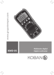
KMD 04
Multímetro digital
Digital multimeter
KMD 04
Multímetro digital
Índice
Introducción
3
Normas de seguridad
3
Descripción
6
Instrucciones de funcionamiento
10
Tensión CC/CA
10
Resistencia
11
Diodos
12
Continuidad
12
Ganancia de transistores hFE
13
Capacitancia
13
Frecuencia
14
Pinza de corriente
14
Corriente CA/CC
15
Especificaciones
15
Mantenimiento
20
Manual de instrucciones | 2
www.grupotemper.com
KMD 04
Multímetro digital
Introducción
Este multímetro ha sido fabricado y examinado según las normas
internacionales de seguridad EN61010-1 para instrumentos de medición
eléctrica y multimetros digitales manuales; posee una Categoría III, un nivel
de sobrecarga de 600V y un grado de contaminación 2. Para asegurar el
mejor uso de este instrumento, lea con atención el manual de instrucciones y
respete las indicaciones de seguridad.
Normas de seguridad
•Las mediciones de categoría III (CAT III) están diseñados para realizar
mediciones dentro de las infraestructuras de los edificios.
Ejemplos: mediciones en armarios de distribución, cableados, tubos
colectores, cajas de conexiones, interruptores, tomas de corriente en
instalaciones fijas, y equipamiento para uso industrial.
•Las Mediciones de categoría II (CAT II) son las que se realizan entre un
enchufe de pared y un dispositivo.
Ejemplos: mediciones en electrodomésticos, herramientas portátiles y
equipos similares.
•Las Mediciones de categoría I (CAT I) so las realizadas sobre componentes
eléctricos.
Ejemplo: mediciones en placas de circuito impreso.
Precauciones
•Deje que el medidor se caliente durante al menos 30 segundos antes de
comenzar a utilizarlo.
•No utilice el medidor cerca de campos con una alta carga magnética, esto
produce mediciones erróneas.
•No utilice el medidor en ambientes con alta presión, temperaturas
elevadas, polvo, gas o vapor.
•Use únicamente las puntas de prueba que vienen con el medidor y
reemplácelas por unas de las mismas especificaciones si comprueba que
están dañadas.
•Asegúrese de que el medidor funciona correctamente probando en
primer lugar una tensión conocida. No lo utilice si nota un funcionamiento
anormal ya que la protección puede estar dañada.
•No realice mediciones de tensión utilizando la toma de entrada 10A.
•Tenga precaución cuando trabaje con tensiones por encima de los 60V CC
www.grupotemper.com
Manual de instrucciones | 3
KMD 04
Multímetro digital
o los 30V CA ya que existe el riesgo de descarga eléctrica. Mantenga los
dedos por detrás de las protecciones cuando realice mediciones de tensión.
•Nunca mida tensiones que excedan los límites de protección especificados.
•Si desconoce el valor de la escala que va a medir, escoja siempre la más
alta.
•A la hora de realizar conexiones, conecte primero la punta de prueba
común antes de la punta de prueba energizada; para desconectarlas hágalo
de modo inverso.
•Antes de seleccionar las diferentes funciones/escalas, desconecte las
puntas de prueba del circuito.
•Para evitar lecturas incorrectas en tensiones de corriente CC, pruebe
primero el circuito en tensión de corriente CA. Después, vuelva al modo de
medición CC.
•Desconecte la potencia de los circuitos y asegúrese de que todos los
condensadores están descargados antes de realizar mediciones.
•Desconecte las puntas de prueba del circuito antes de realizar la prueba de
transistores.
•Antes de realizar mediciones de corriente, desconecte la potencia del
circuito, abra el circuito, conecte las puntas de prueba en serie a lo largo
del mismo y conecte de nuevo la alimentación para comenzar a medir.
•Cambie la pila tan pronto como el símbolo
aparezca en la pantalla. Con
batería baja, el medidor puede que realice mediciones falsas.
Símbolos de seguridad
Precaución: consulte el manual de instrucciones.
CA (Corriente alterna)
CC (Corriente continua)
CA o CC
Conforme a las normas de seguridad de la UE
Toma de tierra
Doble aislamiento
Fusible
Manual de instrucciones | 4
www.grupotemper.com
KMD 04
Multímetro digital
Mantenimiento
•El mantenimiento y ajustes de este tipo de aparatos, debe ser realizado por
un profesional.
•Para asegurar la protección del instrumento frente a incendios, cambie
el fusible únicamente por otro de la misma especificación de tensión y
de escala de corriente que se especifica en este manual: F 400mA/600V y
F2:10A/600V.
•Antes de abrir la carcasa desconecte las puntas de prueba de cualquier
circuito vivo o energizado.
•Nunca utilice el medidor a menos que la tapa trasera se encuentre
perfectamente ajustada.
•Si observa algún tipo de anormalidad, deje de utilizar el medidor
inmediatamente y haga que se lo revisen.
•Si no va utilizar el medidor en un largo período de tiempo, quite la
pila y no lo guarde en un lugar donde esté expuesto a niveles altos de
temperatura o humedad.
www.grupotemper.com
Manual de instrucciones | 5
KMD 04
Multímetro digital
Descripción del instrumento
Panel frontal
1. Escala: para seleccionar entre las diferentes escalas en modo manual.
2. Rel: cuando este botón está pulsado, se muestra la medición actual
comparada con otras mediciones.
3. Hold: botón de retención de datos. Mantiene en la pantalla la lectura
actual.
4. HZ/Duty: selección
entre frecuencia/
ciclos de trabajo
5. Selector giratorio
6. Toma de entrada
.
7. Toma de entrada
COM
8. Toma de entrada
μA/mA/ /hFE.
9. Toma 10A.
Manual de instrucciones | 6
www.grupotemper.com
KMD 04
Multímetro digital
Pantalla
Símbolo
Descripción
Pila con bajo nivel de carga.
Advertencia: : para evitar lecturas falsas que pudieran llevar
a una descarga eléctrica o causar daños personales, cambie la
pila tan pronto como el indicador de bajo nivel de carga.
Polaridad negativa (CC)
Corriente alterna
Corriente continua
Escala automática
Test de diodos
hFE
Modo ganancia de transistores
Modo continuidad
Retención de lecturas
V:
mV:
Voltios (undades de voltage)
milivoltios 1x10⁻³ o 0.001 V
A:
mA:
A:
Amperios (unidades de corriente)
miliamp. 1x10⁻³ A o 0.001 A.
microamp. 1x10⁻⁶ A o 0.000001 A
www.grupotemper.com
Manual de instrucciones | 7
KMD 04
Multímetro digital
Ω:
kΩ:
MΩ:
Ohmio (resistencia)
kilohmios. 1x10³ Ω o 1.000 Ω
megohmios. 1x10⁶ Ω o 1.000.000 Ω
Hz:
kHz:
Mhz:
Herzios (frecuencia)
Kiloherzio. 1x10³ Hz o 1.000 Hz
Megaherzio. 1x10⁶ Hz o 1.000.000 Hz
F:
μF:
nF:
Faradios (capacitancia)
microfaradios 1x10⁻⁶ F o 0.000001 F
nanofaradios. 1x10⁻⁹ F o 0.000000001 F
Sobrecarga (es necesario seleccionar una escala mayor)
Medición relativa
Medición de la pinza medidora accesoria
Botones
Botón
Función
A, mA yμA
Mantener
pulsado al
encender el
medidor
Descripción
Cambiar entre las funciones
Cambiar entre CA/CC
Desactiva el autoapagado
~V, -V, Ω,
mA, μA y A
1. Pulsar RANGE para modo manual.
2. Cada pulsación incrementa la escala.
3. Mantener pulsado RANGE para volver al
modo auto.
Cualquier
función
Pulsar HOLD para mantener las lecturas
en pantalla. Volver a pulsar para liberar las
lecturas.
Cualquier
función excepto
Hz/%
Pulsar REL para mostrar la medición actual
comparada con otras mediciones.
V~, V,
, mA,
μA, A, Hz%
Selecciona entre mediciones de frecuencia y
ciclos de trabajo.
Manual de instrucciones | 8
www.grupotemper.com
KMD 04
Multímetro digital
Selector giratorio
Posición Función
~V
Tensión CA
-V
Tensión CC
Resistencia/Capacitancia/Diodo/Continuidad
Hz%
Frecuencia/Ciclo de Trabajo
hFE
Ganancia de transistores
Para la pinza medidora accesoria
μA
Corriente μA
mA
Corriente mA (hasta 400mA)
A
OFF
Corriente A (hasta 10A)
Posición de apagado
Tomas de entrada
Toma
Descripción
COM
Tensión CC
Toma para tensión, resistencia, capacitancia, diodos, continuidad,
frecuencia, ciclo de trabajo
Toma para corriente μA/mA por debajo de 400mA, transistores y
corriente de la pinza accesoria.
A
Toma para corriente por encima de 400mA.
Accesorios
1
Manual
1 ud
2
Puntas de prueba
1 par
3
Funda
1 piece
www.grupotemper.com
Manual de instrucciones | 9
KMD 04
Multímetro digital
Instrucciones de funcionamiento
Instrucciones generales
Retención de datos
Presione HOLD para mantener la lectura actual en la pantalla. Presione HOLD
de nuevo o cambie a otra función con el selector giratorio para volver al
modo de lectura normal.
Escala Manual/Automática
•El medidor viene por defecto con el modo escala automática seleccionado,
por lo que automáticamente seleccionará la escala de medición apropiada
en cada caso.
•En modo manual, la escala es seleccionada por el usuario.
Para pasar a modo manual:
1.Pulse el botón RANGE, la indicación AUTO desaparecerá de la pantalla.
Con cada pulsación, aumentará un nivel la escala y volverá al inicio
cuando llegue a la más alta.
Nota: pulsando el botón RANGE en el modo retención de datos se
desactiva la función HOLD.
2.Para volver al modo Escala Automática, mantenga pulsado el botón
RANGE hasta que aparezca AUTO en la pantalla.
Autoapagado
Tras 20 minutos sin utilización, el medidor se apagará automáticamente.
Pulse el botón HOLD o gire el selector hacia cualquier posición si lo que
desea es volver a encenderlo.
Funciones de medición
Tensión CC/CA
Precaución
Para evitar descargas eléctricas y/o daños en el aparato, no intente realizar
mediciones que sobrepasen los 600V CC o CA rms.
Escalas de Tensión CC: 400.0mV, 4.000V, 40.00V, 400.0V, 600V. Escalas de
tensión CA: 400.0mV, 4.000V, 40.00V, 400.0V, 600V (la escala 400.0mVsolo
está disponible en modo manual).
Manual de instrucciones | 10
www.grupotemper.com
KMD 04
Multímetro digital
Para medir tensiones de CC/CA:
1.Coloque el selector giratorio en la posición tensión CC o Tensión CA; pulse
RANGE si lo que necesita es seleccionar manualmente la escala que va a
utilizar.
2.Conecte la punta de prueba roja a la entrada V y la punta de prueba negra
a la entrada COM.
3.Las puntas de prueba se deben conectar en paralelo al circuito que va a
medir.
4.Lea los valores tomados en la pantalla. En mediciones de tensión CC, la
polaridad de la punta de prueba roja se mostrará en la pantalla.
Nota: en escalas de tensión muy pequeñas, puede que la pantalla muestre
una lectura incluso antes de conectar las puntas debido a la alta sensibilidad
del medidor. La lectura real aparecerá en cuanto se conecten las puntas de
prueba.
Resistencia
Precaución
Desconecte el circuito y descargue todos los condensadores antes de
hacer mediciones de resistencia.
Escalas de resistencia: 400.0Ω, 4.000kΩ, 40.00kΩ, 400.0kΩ, 4.000MΩ,
40.00MΩ.
Para medir la resistencia:
1.Coloque el selector giratorio en la posición
.
2.Conecte la punta de prueba roja a la toma Ω y la negra a la toma COM.
3.Conecte las puntas a la resistencia o al circuito que va a medir y lea los
valores en la pantalla.
Algunos consejos para medir la resistencia:
•La resistencia medida y la media de la resistencia de los diferentes
componentes a menudo difieren ligeramente. Esto se debe a que la
corriente fluye a través de todos los canales posibles entre las puntas.
•Cuando mida resistencias bajas, cortocircuite las puntas de prueba y
guarde la medición. Luego conecte las puntas a la resistencia y restele del
valor medido el valor guardado.
•Cuando la resistencia es mayor de 1MΩ, espere unos segundos a que se
estabilicen las lecturas.
•Cuando el circuito esté abierto o las puntas no estén conectadas la pantalla
mostrará OL.
www.grupotemper.com
Manual de instrucciones | 11
KMD 04
Multímetro digital
Diodos
Precaución
Desconecte el circuito y descargue todos los condensadores antes de
hacer pruebas en diodos.
Para probar un diodo:
1.Coloque el selector giratorio en la posición
y pulse
una vez
para seleccionar la prueba de diodos.
2.Conecte la punta de prueba roja a la toma
y la negra a la toma COM.
3.Connect the red test lead to the anode (+) and the black lead to the
cathode (-) of the diode.
4. Conecte la punta de prueba negra al ánodo (+) y la punta de prueba
roja al cátodo (-) del diodo y tome los valores de la pantalla. El medidor
mostrará la caída aproximada de tensión del diodo. Si la conexión se
realiza a la inversa, la pantalla mostrará OL.
En un circuito, un buen diodo debería generar siempre una caída de tensión
directa de entre 0.5~0.8V. La lectura de la caída de tensión inversa, puede
variar dependiendo de la resistencia de otros ramales existentes entre las
puntas de la sonda.
Continuidad
Precaución
Desconecte el circuito y descargue todos los condensadores antes de
hacer pruebas de continuidad.
Para probar la continuidad:
1.Coloque el selector giratorio en la posición
y pulse
dos veces
para cambiar al modo continuidad.
2.Conecte la punta de prueba roja a la toma Ω y la negra a la toma COM.
3.Conecte las puntas al circuito que va a probar.
4. El avisador acústico sonará si la resistencia del circuito es menor de 50Ω.
Manual de instrucciones | 12
www.grupotemper.com
KMD 04
Multímetro digital
Ganancia de transistores hFE
Precaución
Para evitar daños en el medidor, desconecte el transistor que va a probar
de cualquier circuito.
Para medir la ganancia del transistor:
1.Coloque el selector giratorio en la posición hFE.
2.Conecte el enchufe multifunción a las tomas de entrada hFE(+) y a la
toma COM.
3.Asegúrese de conectar el transistor en los orificios apropiados del
enchufe multifunción; para ello debe tener en cuenta si el tipo de
transistor es NPN o PNP.
4.La pantalla mostrará la ganancia del transistor.
Capacitancia
Precaución
Desconecte el circuito y descargue todos los condensadores antes de
medir la capacitancia.
Las escalas de capacitancia son: 4.000nF, 40.00nF, 400.0nF, 4.000μF, 40.00μF,
200μF.
Para medir la capacitancia:
1.Coloque el selector giratorio en la posición
y pulse
3 veces
para acceder al modo de medición de capacitancia.
2.Conecte la punta de prueba roja a la toma y la negra a la toma COM.
3.Conecte las puntas al circuito sometido a prueba.
4. Lea la capacitancia medida en la pantalla.
Algunos consejos para mediciones de capacitancia:
Puede que al medidor le lleve unos segundos realizar una lectura estable.
Esto es normal cuando se midan capacitancias muy altas.
www.grupotemper.com
Manual de instrucciones | 13
KMD 04
Multímetro digital
Frecuencia
Precaución
Para evitar descargas eléctricas y/o causar daños al aparato no realice
mediciones de frecuencia en tensiones por encima de los 250V.
Para medir la frecuencia:
1.Coloque el selector giratorio en la posición Hz%.
2.Conecte la punta de prueba roja a la toma de entrada Hz% y la negra a la
toma COM.
3.Conecte las puntas de prueba en paralelo al circuito sometido a prueba.
4.Lea la frecuencia medida en la pantalla.
Nota:
En ambientes muy cargados de electricidad, utilice puntas de prueba
blindadas cuando realice mediciones de frecuencia muy pequeñas.
Pinza de corriente
Precaución
Con el fín de evitar daños personales o en el medidor, no realice
mediciones en tensiones que pudieran superar los 250V CC/CA rms.
1.Coloque el selector giratorio en la posición
y pulse el botón
para
seleccionar entre los modos CA/CC.
2.Conecte la punta roja de la pinza a la toma
y la negra a la COM.
3.Abra el cabezal de la pinza y colóquelo ajustándolo alrededor del
conductor bajo prueba.
4.Lea los valores medidos en la pantalla. Cuando realice mediciones de
corriente CC, la pantalla mostrará la polaridad de la punta roja. Si se
excediese la escala seleccionada, es decir, si hubiera una sobrecarga, la
pantalla mostraría el símbolo OL y deberá seleccionar una escala mayor.
Manual de instrucciones | 14
www.grupotemper.com
KMD 04
Multímetro digital
Corriente CC/CA
Precaución
Para evitar fundir los fusibles, lo que puede provocar daños personales o
al aparato no relice mediciones de corriente cuya tensión pueda ser mayor
de 250V.
Las escalas de corriente son: 400.0μA, 4000.0μA, 40.00mA, 400.0mA, 10.00A.
Para medir la corriente:
1.Desconecte la alimentación del circuito y descargue todos los
condensadores.
2.Coloque el selector giratorio en la posición μA, mA o A.
3.Pulse
para selecionar entre los modos CC/CA.
4.Conecte la punta de prueba roja a la toma μAmA si la corriente que va a
medir es menor de 400mA y a la toma A para mediciones por encima de
400mA y la negra a la toma COM.
5.Corte el circuito y conecte las puntas a lo largo del cortocircuito con la
punta roja en el lado de mayor tensión y la negra en el de menor tensión
6.Conecte la alimentación del circuito y lea los valores medidos en la
pantalla. Si hubiera habido una sobrecarga, la pantalla mostrará el
símbolo OL como indicación de que se ha sobrepasado la escala y
debemos seleccionar una más alta.
Especificaciones
Especificaciones generales
Clasificación de seguridad:
CAT III, 600V; grado de contaminación II
Máx. altitud de
funcionamiento:
<2000m
Temperatura de
funcionamiento/Humedad:
0°C a 40°, <80% HR
Temperatura de almacenaje/
Humedad:
-10°C a 60°C, <70% HR, retire la pila
Coeficiente de temperatura:
0.1 x precisión / ºC(>18ºC o <28ºC)
-Tensión máx. entre las tomas
600V CC o CA rms
y tierra:
www.grupotemper.com
Manual de instrucciones | 15
KMD 04
Multímetro digital
Fusible de protección:
F1 400mA/1000V
F2 10A/600V
Tasa de muestreo:
Aprox. 3 veces/seg.
Pantalla:
LCD 3 ½ digitos. 3999 cuentas
Indicación de sobrecarga:
La pantalla muestra el símbolo OL
Indicación de batería baja:
El símbolo
indica que la batería está por
debajo de su nivel de funcionamiento.
Indicación de polaridad:
Automáticamente la pantalla muestra “-”
Alimentación:
Pila 9V
Dimensiones:
189x91x31.5 mm.
Peso:
approx. 420g (including battery)
Especificaciones técnicas
Precisión: ±(% de lectura + digitos) a 18ºC ~ 28ºC; humedad relativa <80%;
garantizada durante un año.
Tensión CC
Escala
Resolución
400mV
0.1mV
4V
1mV
40V
10mV
400V
100mV
Precisión
±(0.7% de lectura + 2 digitos)
600V
1V
±(0.8% de lectura + 2 digitos)
Impedancia de entrada: 10MΩ.
Tensión máxima de entrada: 600V CC o CA rms.
Manual de instrucciones | 16
www.grupotemper.com
KMD 04
Multímetro digital
AC voltage
Escala
Resolución
Precisión
400mV
0.1mV
±(3.0% de lectura + 3 digitos)
4V
1mV
40V
10mV
400V
100mV
±(0.8% de lectura + 3 digitos)
600V
1V
±(1.2% de lectura + 3 digitos)
Impedancia de entrada: 10MΩ.
Tensión máxima de entrada: 600V CC o CA rms.
Frecuencia de respuesta: escala 4V: 40~400Hz; otras escalas: 40Hz~1kHz
promedio, calibrada en valor eficaz de la onda sinusoidal.
hFE Ganancia de transistores
Escala
hFE
Descripción
Muestra la ganancia
aproximada hFE
(0-1000)
Corriente base: aprox. 10μA
Vce: aprox. 2.8V
Escala
Resolución
Precisión
400Ω
0.1Ω
4kΩ
1Ω
40kΩ
10Ω
400kΩ
100Ω
4MΩ
1kΩ
Resistencia
±(1.2% de lectura + 2 digitos)
40MΩ
10kΩ
±(2.0% de lectura + 5 digitos)
Tensión del circuito abierto: aprox. 0.5V
Protección contra sobrecargas: 250V CC o CA rms.
Continuidad
Función
Descripción
El avisador acústico sonará si la resistencia es menor de 50Ω
Tensión del circuito abierto: aprox. 0.5V
Protección contra sobrecargas: 250V CC o CA rms.
www.grupotemper.com
Manual de instrucciones | 17
KMD 04
Multímetro digital
Diodos
Función
Resolución
Descripción
La pantalla mostrará la caida aproximada de la
tensión.
Corriente CC directa: aprox. 1mA
Tensión CC inversa: aprox. 1.5V
Protección contra sobrecargas: 250V CC o CA rms.
1mV
Capacitancia
Escala
Resolución
4nF
1pF
40nF
10pF
400nF
100pF
4μF
1nF
40μF
10nF
Precisión
±(4.0% de lectura + 15 digitos)
200μF
100nF
Tensión del circuito abierto: aprox. 0.5V
Protección contra sobrecargas: 250V CC o CA rms.
Frecuencia
Escala
Resolución
9.999Hz
0.001Hz
99.99Hz
0.01Hz
999.9Hz
0.1Hz
9.9999kHz
1Hz
99.99kHz
10Hz
199.9kHz
100Hz
Precisión
±(2.0% de lectura + 5 digitos)
>200kHz
100Hz
Sólo como referencia
Protección contra sobrecargas: 250V CC o CA rms.
Escala de tensión de entrada: 0.6~3V CA rms (la frecuencia aumentará con la
tensión)
Frecuencia de respuesta: 10Hz~200kHz onda sinusoidal;
0.5Hz~200kHz onda cuadrada.
Manual de instrucciones | 18
www.grupotemper.com
KMD 04
Multímetro digital
Pinza de corriente
Escala
Resolución
DC40A
1A/1mV
DC400A
1A/1mV
AC40A
1A/1mV
Precisión
±(0.8% de lectura + 3 digitos)
±(1.0% de lectura + 3 digitos)
AC400A
1A/1mV
Impedancia de entrada: 10MΩ.
Tensión máxima de entrada: 250V CC o CA rms.
Corriente CC
Escala
Resolución
400μA
0.1μA
4000μA
1μA
40mA
0.01mA
400mA
0.1mA
Precisión
±(1.2% de lectura + 3 digitos)
10A
10mA
±(2.0% de lectura + 5 digitos)
Protección contra sobrecargas: F1 400mA/1000V; F2 10A/600V
Tensión máxima de entrada: μA/mA: 400mA CC o CA rms; 10A: 10A (no
superar los 4 minutos de medición continua).
Corriente CA
Escala
Resolución
400μA
0.1μA
4000μA
1μA
40mA
0.01mA
400mA
0.1mA
Precisión
±(1.5% de lectura + 5 digitos)
10A
10mA
±(3.0% de lectura + 7 digitos)
Protección contra sobrecargas: F1 400mA/1000V; F2 10A/600V
Frecuencia de respuesta: 40 ~ 400Hz, onda sinusoidal rms (respuesta media)
Corriente máxima de entrada: μA/mA: 400mA CC o CA rms; 10A: 10A (no
superar los 4 minutos de medición continua).
www.grupotemper.com
Manual de instrucciones | 19
KMD 04
Multímetro digital
Mantenimiento
Limpieza
Precaución
Desconecte el medidor y las puntas de prueba de cualquier fuente de
alimentación antes de abrir la carcasa del mismo.
Limpie la carcasa con un paño húmedo y un detergente neutro. No utilice
abrasivos ni disolventes. El polvo o la humedad en las tomas de entrada
puede afectar a las lecturas.
Limpieza de las tomas de entrada:
•Apague el medidor y desconecte as puntas de prueba.
•Extraiga cualquier suciedad que pudiera haber en las tomas.
•Use un detergente o lubricante con un algodón. Use un algodón limpio
para cada toma.
Cambio de las pilas y los fusibles
Precaución
Para evitar daños personales apague el medidor y retire las puntas de
prueba antes de abrir la tapa de la pila.
Cambie los fusibles únicamente por unos de igual clasificación:
F1: F400mA/1000V; F2:F10A/600V
Para cambiar las pilas y los fusibles:
1.Apague el multímetro.
2.Desconecte las puntas de prueba de las tomas.
3.Use un destornillador para quitar la tapa trasera del multímetro.
4.Quite la pila usada y cámbiela por una de 9V.
5.Quite y cambie los fusibles fundidos por unos nuevos.
6.Vuelva a colocar la tapa trasera.
Manual de instrucciones | 20
www.grupotemper.com
KMD 04
Digital multimeter
Contents
Introduction
22
Safety guidelines
22
Instrument description
24
Operating instructions
28
AC/DC voltage
28
Resistance
29
Diodes
30
Continuity
30
hFE Transistor gain
31
Capacitance
31
Frequency
32
Clamp current
32
AC/DC current
33
Specifications
33
Maintenace
38
www.grupotemper.com
Instructions manual | 21
KMD 04
Digital multimeter
Introduction
This digital multimeter complies with international safety standards
EN61010–1 electrical safety requirements for electronic measuring
instruments and handheld digital multimeters; CAT III 600V and pollution
degree of 2. Read all instructions carefully before using the meter and follow
all relevant safety standards.
Safety guidelines
Safety category Information
•Category III mesurements (CAT III) are measurements done inside the
infraestructure of a building.
Example: fixed equipment switchboards, circuit breakers, wiring, including
cables, bus bars, junction boxes, switches, sockets, output terminals on
devices for industrial use and other equipment.
•Category II measurements (CAT II) are measurements done between the
wall socket and a device.
Example: measurements on household appliances, portable tools and
similar equipment.
•Category I measurements (CAT I) are measurements done at the
component level.
Example: surface mounted devices on a circuit board.
Precautions
•Allow the meter to warm up for 30 sec. before use.
•Do not place meter in a strong magnetic field, this may cause false redings.
•Do not place the meter in any environment with high pressure, high
temperature, dust, explosive gas or vapor.
•Inspect the case before use. Check for cracks in the casing and the
insulation around the input sockets.
•Only use the test leads provided with the meter. If leads are damaged or
need to be replaced, use similar leads with matching specifications.
•Ensure the meter works properly by testing a known voltage source first. If
not working properly, the protective equipment my be damaged; have the
meter serviced before using.
•Make sure the test leads are in the correct input jacks before measurement.
Instructions manual | 22
www.grupotemper.com
KMD 04
Digital multimeter
•Do not perform a voltage test using the 10A input jack.
•Always be careful when working with voltages above 60V DC or 30V
AC rms. Keep fingers behind the probe barriers when making voltage
measurements.
•Never exceed the protection limit values indicated in the specifications for
each range of measurement.
•Choose the highest range when the value to be measured is unknown
beforehand.
•Whe connecting the test leads to a measurement circuit, connect the
common lead first, the the live lead. Reverse when disconnecting.
•Disconnect leads from circuit before switching functions/ranges.
•In order to avoid incorrect DC voltage readings, check the circuit for AC
voltage first, then put the meter in the appropriate DC voltage range.
•Turn off the power to circuit and discharge all capacitors before making
resistance, continuity or diode measurements.
•Disconnect leads from circuit before testing transistors.
•before making current measurements, turn off power to the circuit, break
the circuit, connect the leads in series across the break, the turn the power
back on for measurement.
•When the
symbol appears, replace the batteries to avoid incorrect
readings.
Safety Symbols
Caution: refer to the instruction manual. Incorrect use may
result in damage to the device or its components.
AC (Alternating Current)
DC (Direct Current)
AC or DC
Conforms to European Union directives
Earth ground
Double insulated
Fuse
www.grupotemper.com
Instructions manual | 23
KMD 04
Digital multimeter
Instrument description
Front Panel
1. Range: switches between ranges in manual mode.
2. Rel: shows current measurement as compared to measurement when
botton is pressed.
3. Hold: keeps current reading on display.
4. HZ/Duty: switches
between frequency/
duty cycle.
5. Rotary switch
6.
input jack.
7. COM imput jack
8. μA/mA/ /hFE input
jack.
9. 10A input jack.
Instructions manual | 24
www.grupotemper.com
KMD 04
Digital multimeter
Display
Symbol
Description
The battery is low.
Warning: to avoid false readings, which could lead to
possible electric shock or personal injury, replace the battery as
soon as the battery indicator appears.
Negative polarity (DC)
Alternating current
Direct current
Auto-range
Diode mode
hFE
Transistor gain mode
Continuity mode
Reading hold
V:
mV:
Volts (voltage units)
milivolts 1x10⁻³ or 0.001 V
A:
mA:
A:
Amps (current units)
miliamp. 1x10⁻³ A or 0.001 A.
microamp. 1x10⁻⁶ A or 0.000001 A
www.grupotemper.com
Instructions manual | 25
KMD 04
Digital multimeter
Ω:
kΩ:
MΩ:
Ohm (resistance)
kilohms. 1x10³ Ω or 1.000 Ω
megohms. 1x10⁶ Ω or 1.000.000 Ω
Hz:
kHz:
Mhz:
Hertz (frequency)
Kilohertz. 1x10³ Hz or 1.000 Hz
Megahertz. 1x10⁶ Hz or 1.000.000 Hz
F:
μF:
nF:
Farads (capacitance)
microfarads 1x10⁻⁶ F or 0.000001 F
nanofarad. 1x10⁻⁹ F or 0.000000001 F
Overload (need to select a higher range)
Relative measurement
Current clamp attachment measurement
Buttons
Button
Function
A, mA and
μA
Hold when
turning
meter
Description
Switch between functions
Switch between AC/DC
Turns off autor power off
1. Press RANGE to enter manual range.
~V, -V, Ω,
2. Each press increases the range.
mA, μA and A
3. Hold RANGE to return to auto-range
Any function
Press HOLD to keep current reading on the
display. Press again to release the hold.
Any function
except Hz/%
Press REL to show current reading relative to the
reading when button was pressed.
V~, V,
, mA, μA, A,
Hz%
Switch between frequency and duty cycle
measurements.
Instructions manual | 26
www.grupotemper.com
KMD 04
Digital multimeter
Rotary switch
Position Function
~V
AC Voltage
-V
DC Voltage
Resistance/Capacitance/Diode/Continuity
Hz%
Frequency/Duty Cycle
hFE
hFE Transistor Gain
For optional current clamp attachment
μA
μA current
mA
mA current (up to 400mA)
A
OFF
A current (up to 10A)
Off position
Input jacks
Jack
Description
COM
DC Voltage
Input for voltage, resistance, capacitance, diodes, continuity,
frequency, duty cycle
Input for μA/mA current below 400mA, transistor, current clamp
attachment
A
Input for current above 400mA
Accesories
1
Manual
1 piece
2
Test leads
1 pair
3
Case
1 piece
www.grupotemper.com
Instructions manual | 27
KMD 04
Digital multimeter
Operating instructions
General Instructions
Data Hold
Press HOLD to keep the current reading on the display. To release the hold,
press HOLD again or switch functions on the rotary swtch to return to normal
readings.
Manual/Auto Range
•The meter’s defaultr range is auto-range. The meter will automatically pick
the appropriate range for measurement.
•In manual range, the rangeis specified by the user, locking the display into
one specific range.
To enter manual range:
1.Press the RANGE button. AUTO will disappear from the display. Each press
of the button will increase the range and return to the lowest range once
pressed at the highest range.
Note: if you press RANGE while in data hold mode, the meter will release
the hold.
2.To return to auto-range mode, hold RANGE until AUTO appears on the
display.
Auto Power off
After 20 minutes of non-use the meter will turn itself off. Press HOLD or turn
the rotary switch to any position to turn the meter back on.
Measurement Operation
DC/AC Voltage
Warning
To prevent personal injury or damage to the meter, do not measure
voltages that might exceed 600V DC/AC rms.
DC voltage ranges: 400.0mV, 4.000V, 40.00V, 400.0V, 600V. AC voltage ranges:
400.0mV, 4.000V, 40.00V, 400.0V, 600V (400.0mV range only available in
manual range).
Instructions manual | 28
www.grupotemper.com
KMD 04
Digital multimeter
To measure DC/AC voltage:
1.Turn the rotary switch to the DC or AC voltage position; press RANGE for
manual range if needed.
2.Connect the red test lead to the V input jack and the black test lead to the
COM jack.
3.Connect the test leads in parallel to the circuit undertest.
4.Read the measured voltage on the display. When measuring DC
voltage,the display will show the polarity of the red lead.
Note: In small voltage ranges, the display may show a reading before leads
are connected. This is normal because of the high sensitivity of the meter.
Once the leads are connected to a circuit the true voltage will be displayed.
Resistance
Warning
Turn off all power and discharge all capacitors before making resistance
mesurements.
Resistance ranges are: 400.0Ω, 4.000kΩ, 40.00kΩ, 400.0kΩ, 4.000MΩ,
40.00MΩ.
To measure resistance:
1.Turn the rotary switch to the
position. The default mode is
resistance.
2.Connect the red test lead to the Ω input jack and the black test lead to the
COM jack.
3.Connect the leads to the resistance or circuit under test.
4.Read the measured resistance on the display.
Tips for measuring resistance:
•Measured resistance and a components rated resistance often differ
slightly. This is normal due to the test current flowing through all possible
paths between the leads.
•When measuring low resistances, short the test leads and record the
measurement. Then connect the leads to the resistance to be measured
and subtract the shorted resistance from the measured resistance.
•When the measured resistance is greater than 1MΩ, wait a few seconds for
readings to stabilize. This is normal for high resistance measurements.
•When the circuit is open or leads not connected, the display will show OL.
www.grupotemper.com
Instructions manual | 29
KMD 04
Digital multimeter
Diodes
Warning
Turn off all power and discharge all capacitors before testing diodes.
To test a diode:
1.Turn the rotary switch to the
position. Press
once to switch to
diode mode.
2.Connect the red test lead to the
input jack and the black test lead to
the COM jack.
3.Connect the red test lead to the anode (+) and the black lead to the
cathode (-) of the diode.
4. The display will show the forward biased voltage drop. If the leads are
reversed, the display nwill show OL.
In a circuit, a good diode will produce a voltage drop between .05~0.8V.
Reverse bias readings will depend on the resistance of the pathways between
the leads.
Continuity
Warning
Turn off all power and discharge all capacitors before testing continuity.
To test a continuity:
1.Turn the rotary switch to the
position. Press
twice to switch
to continuity mode.
2.Connect the red test lead to the Ω input jack and the black test lead to the
COM jack.
3.Connect the leads to the circuit under test.
4. If the measured resistance is less than 50Ω, the buzzer will sound.
Instructions manual | 30
www.grupotemper.com
KMD 04
Digital multimeter
hFE Transistor gain
Warning
Remove the transistor under test from any circuit to prevent damage to
the meter.
To measure transistor gain:
1.Turn the rotary switch to the hFE position.
2.Connect the multi-function socket to the hFE (+) input jack and the COM
jack.
3.Connect the transistor to the appropriate holes in the multi-function
socket depending on the type of transistor (NPN or PNP).
4.The display will show the measured transistor gain.
Capacitance
Warning
Turn off all power and discharge all capacitors before testing capacitance.
Capacitance ranges are: 4.000nF, 40.00nF, 400.0nF, 4.000μF, 40.00μF, 200μF.
To measure capacitance:
1.Turn the rotary switch to the
position. Press
3 times to switch
to capacitance mode.
2.Connect the red test lead to the input jack and the black test lead to the
COM jack.
3.Connect the leads to the circuit under test.
4. Read the measured capacitance on the display.
Tips for measuring capacitance:
When measuring large capacitances, wait a few seconds for readings to
stabilize. This is normal for high capacitance measurements.
www.grupotemper.com
Instructions manual | 31
KMD 04
Digital multimeter
Frequency
Warning
To prevent personal injury or damage to the meter, do not measure
frequency with larger than 250V AC rms present.
To measure frequency:
1.Turn the rotary switch to the Hz% position.
2.Connect the red test lead to the Hz% input jack and the black test lead to
the COM jack.
3.Connect the test leads in parallel to the circuit under test.
4.Read the measured frequency on the display.
Note:
In electrically noisy environments, use shielded test leads to make small
frequency measurements.
Clamp current
Warning
To prevent personal injury or damage to the meter, do not measure with
voltages present that might exceed 250V DC/AC rms.
1.Turn the rotary switch to the
position. Press
to switch between AC/
DC modes.
2.Connect the red lead of the clamp attachment to the
input jack and
the black lead to the COM jack.
3.Open the clamp head and clamp it around the conductor under test.
4. Read the measured current on the display. When measuring DC current,
the display will show the polarity of the red lead. lf the display shows OL
the input has exceed the selected range; select a higher range.
Instructions manual | 32
www.grupotemper.com
KMD 04
Digital multimeter
DC/AC Current
Warning
Do not measure current when voltages might exceed 250V to avoid
blowing the fuses which can lead to,personal injury or damage to the
meter.
Current ranges are: 400.0μA, 4000.0μA, 40.00mA, 400.0mA, 10.00A.
To measure current:
1.Turn off power to circuit and discharge all capacitors.
2.Turn the rotary switch to the μA, mA or A position.
3.Press
to switch between DC/AC modes.
4.Connect the red test lead to the μAmA input jack if measured current is
less than 400mA, the A input jack for measurements above 400mA and
the black test lead to the COM jack.
5.Break the circuit and connect the leads in series across the break with the
red lead at the higher voltage side and the blck lead on the lower voltage
side.
6.Turn on power to the circuit and read the measured current on the display.
If the display shows OL the measured value has exceed the selected
range. Move the rotary switch to the next higher current position.
Specifications
General specifications
Safety Rating:
CAT III, 600V; pollution degree II
Operating altitude:
<2000m
Operating Temperature/
Humidity:
0°C to 40°, <80% RH
Storage Temperature/
Humidity:
-10°C to 60°C, <70% RH, remove battery
Temperature coefficient:
0.1 x accuracy/ºC(>18ºC or <28ºC)
Max. Input between terminals
600V DC or AC rms
and earth ground:
www.grupotemper.com
Instructions manual | 33
KMD 04
Digital multimeter
Fuse protection:
F1 400mA/1000V
F2 10A/600V
Sample rate:
Approx. 3 times/sec.
Display:
3 ½ digit LCD display, max. reading: 3999
Overload Indication:
Display shows OL
Low Battery Indication:
When battery voltage drops below normal
operating voltage,
is shown on the
display.
Polarity Indication:
Display automatically displays “-”
Power:
1 x 9V battery
Dimensions:
189x91x31.5 mm.
Weight:
approx. 420g (including battery)
Technical specifications
Accuracy: ±(% of reading + digits) at 18ºC ~ 28ºC with relative humidity of
<80%; guaranteed for a period of one year.
DC Voltage
Range
Resolution
400mV
0.1mV
4V
1mV
40V
10mV
400V
100mV
600V
1V
Input impedance: 10MΩ.
Max. input voltage: 600V DC or AC rms.
Instructions manual | 34
Accuracy
±(0.7% of reading + 2 digits)
±(0.8% of reading + 2 digits)
www.grupotemper.com
KMD 04
Digital multimeter
AC voltage
Range
Resolution
Accuracy
400mV
0.1mV
±(3.0% of reading + 3 digits)
4V
1mV
40V
10mV
400V
100mV
±(0.8% of reading + 3 digits)
600V
1V
±(1.2% of reading + 3 digits)
Input impedance: 10MΩ.
Max. input voltage: 600V DC or AC rms.
Frequency response: 4V range: 40~400Hz; other ranges: 40Hz~1kHz sine
wave rms (avg. response)
hFE Transistor Gain
Range
hFE
Description
Displays approx.
hFE transistoir gain
(0-1000)
Base current: approx. 10μA Vce:
approx. 2.8V
Range
Resolution
Accuracy
400Ω
0.1Ω
4kΩ
1Ω
40kΩ
10Ω
400kΩ
100Ω
4MΩ
1kΩ
Resistance
±(1.2% of reading + 2 digits)
40MΩ
10kΩ
±(2.0% of reading + 5 digits)
Open circuit voltage: approx. 0.5V
Overload Protection: 250V DC or AC rms.
Continuity
Function
Description
The buzzer will sound if the measured resistance is less than
50Ω
Open circuit voltage: approx. 0.5V
Overload Protection: 250V DC or AC rms.
www.grupotemper.com
Instructions manual | 35
KMD 04
Digital multimeter
Diodes
Function
Resolution
Description
The display shows the approx. forward voltage
drop.
Forward DC current: approx. 1mA
Reverse DC voltage: approx. 1.5V
Overload protection: 250V DC or AC rms.
1mV
Capacitance
Range
Resolution
4nF
1pF
40nF
10pF
400nF
100pF
4μF
1nF
40μF
10nF
Accuracy
±(4.0% of reading + 15 digits)
200μF
100nF
Open circuit voltage: approx. 0.5V
Overload Protection: 250V DC or AC rms.
Frequency
Range
Resolution
9.999Hz
0.001Hz
99.99Hz
0.01Hz
999.9Hz
0.1Hz
9.9999kHz
1Hz
99.99kHz
10Hz
199.9kHz
100Hz
Accuracy
±(2.0% of reading + 5 digits)
For reference only
>200kHz
100Hz
Overload Protection: 250V DC or AC rms.
Input voltage range: 0.6~3V AC rms (as frequency increases, input voltage
increases)
Frequency response: 10Hz~200kHz sine wave;
0.5Hz~200kHz square wave.
Instructions manual | 36
www.grupotemper.com
KMD 04
Digital multimeter
Clamp Current
Range
Resolution
DC40A
1A/1mV
DC400A
1A/1mV
AC40A
1A/1mV
AC400A
1A/1mV
Input impedance: 10MΩ.
Max. input voltage: 250V DC or AC rms.
Accuracy
±(0.8% of reading + 3 digits)
±(1.0% of reading + 3 digits)
DC Current
Range
Resolution
400μA
0.1μA
4000μA
1μA
40mA
0.01mA
400mA
0.1mA
Accuracy
±(1.2% of reading + 3 digits)
10A
10mA
±(2.0% of reading + 5 digits)
Overload Protection: F1 400mA/1000V; F2 10A/600V
Max. input current: μA/mA: 400mA DC or AC rms; 10A: 10A (do not exceed 4
min.)
AC Current
Range
Resolution
400μA
0.1μA
4000μA
1μA
40mA
0.01mA
400mA
0.1mA
Accuracy
±(1.5% of reading + 5 digits)
10A
10mA
±(3.0% of reading + 7 digits)
Overload Protection: F1 400mA/1000V; F2 10A/600V
Frequency response: 40 ~ 400Hz, sine wave rms (avg. response)
Max. input current: μA/mA: 400mA DC or AC rms; 10A: 10A (do not exceed 4
min.)
www.grupotemper.com
Instructions manual | 37
KMD 04
Digital multimeter
Maintenace
Cleaning meter
Warning
Before opening the back cover, turn off the meter and disconnect test
leads from any circuit.
Clean meter with a damp cloth and mild detergent; do not use chemical
solvents on the meter. Dirt or moisture on the inputjacks can affect the
reading of the meter.
•Turn the rotary switch to OFF and remove test leads.
• Remove all dirt from the input jacks.
•Use a detergent or lubricant with a cotton swab to clean the jacks. Use a
new cotton swab for each jack to prevent cross contamination.
Changing Battery/fuses
Warning
To avoid electric shock and personal injury, turn off the meter and remove
the test leads before opening the battery cover.
Replace fuses with ones that have the exact same ratings:
F1: F400mA/1000V; F2:F10A/600V
To replace battery and fuses:
1.Turn off the meter.
2.Disconnect test leads from input jacks.
3.Use a screwdriver and remove the back cover from the meter.
4.Remove used battery and replace with a new 9V battery.
5.Remove and replace blow fuses with new ones.
6.Replace back cover before using meter again.
Instructions manual | 38
www.grupotemper.com
GARANTÍA • WARRANTY
GARANTIE • GARANTIA
2
años
years
années
anos
TEMPER ENERGY INTERNATIONAL S.L.
garantiza este aparato por 2 años ante
todo defecto de fabricación. Para hacer
válida esta garantía, es imprescindible
presentar con este resguardo el ticket o
factura de compra.
TEMPER ENERGY INTERNATIONAL
S.L. garantit cet apareil pour le durée
de 2 annèes contre tout défault de
fabrication. Pour le service de garantie,
vous devez présenter ce reçu avec du
ticket de caisse ou la facture.
TEMPER ENERGY INTERNATIONAL S.L.
guarantees this device during 2 years
against any manufacturing defect. For
warranty service, you must present this
receipt with the purchase receipt or
invoice.
TEMPER ENERGY INTERNATIONAL S.L.
garantía este aparelho contra defeitos
de fábrica ate 2 anos. Para o serviço
de garantia, você deve apresentar este
recibo com o recibo de compra ou
fatura.
Ref. Art.
Nº serie / Serial number
Nombre / Name / Nom / Nombre
Fecha de venta / Date of purchase
Date de vente / Data de venda
Sello establecimiento vendedor / Dealer stamp
Cachet du commercant / Cambo da firma
TEMPER ENERGY INTERNATIONAL S.L.
Polígono industrial de Granda, nave 18
33199 • Granda - Siero • Asturias
Teléfono: (+34) 902 201 292
Fax:
(+34) 902 201 303
Email:
[email protected]
Una empresa
del grupo