1
User Instruction
Manual
Manuel D'utilisation
Manual de Instrucciones
para El Usuario
Table of Contents
1.0 General Requirements, Warnings and Limitations
2.0 System Compatibility
3-4
4-5
2.1 Miller Fall Protection Product Groups / 2.2 Component Warnings and Limitations
3.0 Making Connections
6-7
3.1 Making Connections to the Body Support and Anchorage
3.2 Connecting Tie-Back Lanyards / 3.3 Connecting a Choke-Through Loop Lanyard
3.4 Connecting a Lanyard with Integral 0-Ring Extension Option
3.5 Connecting an 0-Ring or D-Ring Extension
4.0 Calculating Fall Clearance Distance
5.0 Inspection and Maintenance
7
8-9
5.1 Lanyard Inspection / 5.2 Types of Material Damage / 5.3 Cleaning and Storage
5.4 Life Expectancy of Miller Brand Lanyards
Family Identification
24-28
Manyard, HP Manyard, and Manyard 11 Shock-Absorbing Lanyards
StretchStop Lanyards, Lanyards, and HP Lanyards with SofStop Shock Absorber
BackBiter Tie-Back Lanyards with SofStop Shock
Positioning and Restraint Lanyards and 0-Ring and D-Ring E
Than Shook-Absorbing Lanyards and Titan Tie-Back Lanyards
Titan Positioning Lanyards
Parts Identification
Product Labels
Inspection and Maintenance Log
Warranty
29
30-35
36
37
Table des Matieres
1.0 Exigences Generales, Avertissements et Limitations
2.0 Compatibilite du Systeme
3.0 Raccordements
4.0 Calcul de La Distance de Degagement
5.0 Inspection et Entretien
Identification par Famille
Identification des Pieces
Liquefies sur les Produits
Registre D'inspection et D'entretien
Garantie
10-11
11-12
13-14
14
15-16
24-28
29
30-35
36
37
Indice
1.0 Requisitos Generales, Advertencias y Limitaciones
2.0 Compatibilidad del Sistema
3.0 RealizaciOn de Conexiones
4.0 Calculo de La Distancia Segura de Caida
5.0 Inspeccion y Mantenimiento
Identificacion de Familias de Productos
Identificacion de Piezas
Etiquetas de los Productos
Registro de Inspeccion y Mantenimiento
Garantia
2
17-18
18-19
20-21
21
22-23
24-28
29
30-35
36
37
User Instructions - English
Thank You
Thank you for your purchase of Miller Fall Protection equipment. Miller brand products are produced to meet the highest standards of quality at our ISO 9001:2000 certified facility. Miller Fall
Protection equipment will provide you with years of use, if cared for properly.
A WARNING
All persons using this equipment must read, understand and follow all instructions.
Failure to do so may result in serious injury or death. Do not use this equipment unless you are properly trained.
Questions?
CALL
1.800.873.5242
It is crucial that the authorized person/user of this fall protection equipment read and understand
these instructions. In addition, it is the employer's responsibility to ensure that all users are trained
in the proper use, inspection, and maintenance of fall protection equipment. Fall protection training
should be an integral part of a comprehensive safety program.
Proper use of fall arrest systems can save lives and reduce the potential of serious injuries from a
fall. The user must be aware that forces experienced during the arrest of a fall or prolonged suspension may cause bodily injury. Consult a physician if there is any question about the user's ability
to use this product. Pregnant women and minors must not use this product.
1.0 General Requirements,
Warnings and Limitations
Equipment must not be altered in any way.
Repairs must be performed only by the
manufacturer, or persons or entities authorized
in writing by the manufacturer.
All warnings and instructions shall be provided
to authorized persons/users.
All authorized persons/users must reference
the regulations governing occupational
safety, as well as applicable ANSI or
CSA standards. Please refer to product
labeling for information on specific OSHA
regulations, and ANSI and CSA standards
met by product.
Any product exhibiting deformities, unusual
wear, or deterioration must be immediately
discarded.
Any equipment subject to a fall must be
removed from service.
Proper precautions should always be taken to
remove any obstructions, debris, material, or
other recognized hazards from the work area
that could cause injuries or interfere with the
operation of the system.
The authorized person/user shall have a rescue
plan and the means at hand to implement it
when using this equipment.
Never use fall protection equipment for
purposes other than those for which it was
designed. Fall protection equipment should
never be used for towing or hoisting.
All equipment must be inspected before
each use according to the manufacturer's
instructions.
All synthetic material must be protected from
slag, hot sparks, open flames, or other heat
sources. The use of heat resistant materials is
recommended in these applications.
All equipment should be inspected by a
qualified person on a regular basis.
To minimize the potential for accidental
disengagement, a competent person must
ensure system compatibility.
Never use natural materials (manila, cotton,
etc.) as part of a fall protection system.
3
User Instructions - English
Environmental hazards should be considered
when selecting fall protection equipment.
Equipment must not be exposed to chemicals
which may produce a harmful effect. Polyester
should be used in certain chemical or acidic
environments. Consult the manufacturer in
cases of doubt.
Do not allow equipment to come in contact
with anything that will damage it including, but
not limited to, sharp, abrasive, rough or hightemperature surfaces, welding, heat sources,
electrical hazards, or moving machinery.
Always check for obstructions below the work
area to make sure potential fall path is clear.
Allow adequate fall clearance below the work
surface.
Never remove product labels, which include
important warnings and information for the
authorized person/user.
Maximum working load is 310 lbs. (140.6kg),
including tools, unless labeled otherwise.
2.0 System Compatibility
All Miller fall protection products are designed for use with Miller approved components. Substitution
or replacement with non-approved component combinations or subsystems or both may affect or
interfere with the safe function of each other and endanger the compatibility within the system. This
incompatibility may affect the reliability and safety of the total system.
2.1 Miller Fall Protection Product Groups
A comprehensive fall protection program must be viewed as a "total system" beginning with hazard
identification and ending with ongoing management review. Miller Fall Protection views its products
as a "system within a system." Three key components of the "Miller System" need to be in place and
properly used to provide maximum worker protection.
A. ANCHOR POINT/ANCHORAGE CONNECTOR
The first component is the anchor point/anchorage connector.
The anchor point, also referred to as the tie-off point, is a secure
point of attachment for connecting devices and must be capable of
supporting 5,000 lbs. (22.2kN) per worker or meet OSHA 1926.502
requirements for a safety factor of two, such as an I-beam or other
support structure. Anchorage connectors, such as the cross-arm
strap and eyebolt, are sometimes necessary to make compatible
connections between the connecting device and the anchor point.
B. BODY WEAR
The second system component is the personal protective gear
worn by workers while performing the job. Miller Fall Protection
manufactures full-body harnesses, positioning belts and body belts
for use in specific work environments. Full-body harnesses are
engineered to aid in the arrest of a free fall and should be worn in all
situations where workers are exposed to a potential free fall. The
full-body harness must be used in conjunction with shock-absorbing
equipment to keep fall forces to a minimum. It is imperative that the
harness be worn properly.
C. CONNECTING DEVICE
The third component of the system is the connecting device. The most important feature of the
connecting device is the built-in shock absorber. Whether the connecting device is a shockabsorbing lanyard or self-retracting lifeline, they are designed to dramatically reduce fall arresting
forces. Rope, web or cable lanyards being used for fall arrest MUST be used in conjunction with a
shock absorber (i.e., Miller SofStop pack).
Individually, none of these components will provide protection from a fall. Used properly
with each other, they form the "Miller System" and become a critically important part of the
"total fall protection system."
4
User Instructions - English
A
2.2 Component Warnings and Limitations
ANCHORAGES
• Anchorages must be capable of supporting 5,000 pounds (22.2kN) per worker or meet OSHA
1926.502 requirements for a safety factor of two.
• Anchorage requirements based on ANSI are as follows:
• For fall arrest systems, anchorages must withstand a static load of 5,000 lbs. (22.2kN) for noncertified anchorages or two times the maximum arresting force for certified anchorages.
• For positioning systems, anchorages must withstand a static load of 3,000 lbs. (13.3kN) for noncertified anchorages or two times the foreseeable force for certified anchorages.
• For travel restraint, anchorages must withstand a static load of 1,000 lbs. (4.5kN) for non-certified
anchorages or two times the foreseeable force for certified anchorages.
• When more than one personal fall arrest system is attached to an anchorage, the above anchorage
strengths must be multiplied by the number of personal fall arrest systems attached to the anchorage.
• Always work directly under the anchor point to avoid a swing-fall injury.
• Ensure that the anchorage connector is at a height that will not allow a lower level to be struck should a
fall occur.
• When selecting an anchorage point, always remember that shock absorbers may elongate up to
3-1/2 feet (1.07m).
• Ensure that the anchor point is at a height that limits free fall distance to 6 feet (1.8m) or less.
• Anchorage connector must be compatible with snap hook or carabiner and must not be capable of
causing a load to be applied to the keeper.
• Never use an anchorage connector which will not allow snap hook or carabiner keeper to close.
BODY WEAR
• Visually check all buckles to assure proper and secure connections before each use. All straps
must be connected and adjusted to provide a snug fit.
• Fall protection connecting devices should be attached to the back D-ring of a full-body harness. A
front D-ring attachment element may be used for fall arrest only in rescue, work positioning, rope
access, and other ANSI Z359.1 recognized applications where the personal fall arrest system limits
the maximum free fall distance to 2 ft. (0.6m) and limits the maximum arrest force to 900 lbs. (4.0kN).
• Side and front D-rings should be used for positioning only. (Note front D-ring exception above.)
• Shoulder D-rings should be used for retrieval only.
• Never attach non-locking snap hooks to a harness D-ring.
• Never attach rebar (pelican) hooks to a harness D-ring.
• Body belts should be used for positioning only.
CONNECTING DEVICES
• Make only compatible connections.
• Use only connecting devices containing locking snap hooks or auto-locking carabiners.
• Always visually check that each snap hook and carabiner freely engages the D-ring or anchor
point, and that its keeper is completely closed and locked.
• Never disable or restrict locking keeper or alter connecting device in any way.
• Make sure snap hook/carabiner is positioned so that its keeper is never load bearing.
• The use of shock absorbers is required to reduce fall arresting forces. Miller shock absorbers,
constructed of polyester, limit maximum fall arrest force to 900 lbs. (4kN).
• Average arrest force = 874 lbs. (3.8kN)
• Shock absorbers can elongate up to 3-1/2 feet (1.07m). This maximum elongation distance must be
considered when choosing an anchor point.
• Tie-off in a manner which ensures a lower level will not be struck should a fall occur.
• Connect in a manner that limits free fall to the shortest possible distance. [6ft. (1.8m) maximum]
• Never rig a two-legged lanyard to create more than a six-foot free fall.
• Never allow a retractable lanyard or lifeline to become slack.
• Never allow a lanyard, or either leg of a two-legged lanyard, to pass under or entwine around the
user's arms, legs, neck or any other obstacle.
• Do not tie knots in lanyards or lifelines, or wrap around sharp, rough edges, or small diameter
structural members.
• Do not attach multiple lanyards together, or attach a lanyard back onto itself unless it is specifically
designed for that purpose.
5
User Instructions - English
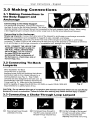
3.0 Making Connections
3.1 Making Connections to
the Body Support and
Anchorage
Connecting to the Body Support
For general fall protection, connect the lanyard to
the back D-ring on the full-body harness. The shock
absorber portion of the lanyard should be connected to the body support (back D-ring). When using
a two-legged lanyard, connect only the center snap hook to the fall arrest attachment element.
Connecting to the Anchorage
Single leg lanyards: Connect the other end of the lanyard to anchorage or anchorage connector.
CORRECT
NOTE: CONNECT THE LEG OF THE
LANYARD THAT IS NOT IN USE TO
THE PULL-FREE LANYARD RING
OR CLIP ONLY. Do not connect
the spare leg of the lanyard to
permanently fixed components of
the harness (i.e., chest strap, side or
front D-rings, etc.).
IN CORRECT
Make sure connections are compatible in regards to size, strength, and shape.
Double leg lanyards: Connect one of the free ends of the lanyard to anchorage or anchorage
connector. To retain 100% tie off, make sure at least one leg of the lanyard is connected at all times
to an anchorage or anchorage connector of compatible size, strength and shape.
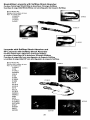
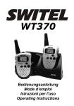
3.2 Connecting Tie-Back
Lanyards
Miller BackBiter Tie-Back
Lanyards have a specially
designed snap hook and webbing that allows
connection back to the integral lanyard in a
choking fashion (see Fig. 1). Titan T-BAK
Lanyards are also designed for tie-back use by
Fig. 1
connecting the auto-lock carabiner back into the
0-ring (see Fig. 2). Make sure the connection
point is capable of supporting 5,000 lbs. (22.2kN) or meets OSHA 1926.502
requirements for a safety factor of two.
Fig. 2
CAUTION: Do not attempt this type of connection with standard lanyards which are not specifically
designed for such a connection. Failure to follow this warning may cause serious injury or death!
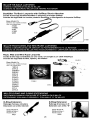
3.3 Connecting a Choke-Through Loop Lanyard
®
Pass lanyard loop through 0 Pull lanyard loop through Dunderside of D-ring.
ring then pass opposite end of
lanyard through lanyard loop.
6
0 Pull the full length of the lanyard
through loop and tighten choke
by pulling on lanyard while
adjusting loop evenly over D-ring.
User Instructions - English
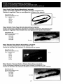
3.4 Connecting a Lanyard
with Integral 0-Ring Extension Option
The 0-Ring Extension Option is available on any Miller shock-absorbing
lanyard and provides either a choke-through loop or snap hook on the 0-ring
extension end, which connects to the back D-ring of the harness. Once attached, the user may use the lanyard or a retractable, which is connected to
the 0-ring of the lanyard.
3.5 Connecting a D-Ring or 0-Ring Extension
The 0-Ring or D-Ring Extension is simply a separate webbing extension with
a snap hook or loop on one end and a D-ring or 0-ring on the other and is
connected between the harness back D-ring and the lanyard being used as
shown.
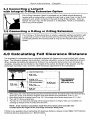
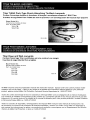
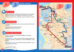
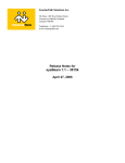
4.0 Calculating Fall Clearance Distance
It is important to understand how to calculate potential fall clearance to avoid contact with a lower
level. The following diagram demonstrates a sample calculation using a shock-absorbing lanyard.
When actually calculating fall clearance distance, the authorized person/user must consider all
variables, including but not limited to, the height of the worker, the length of the lanyard, and the
anchorage connector used, and then make necessary adjustments to the calculations.
Before Fall
Atter Fail
Length of Anehorap Gax 1p
6 ft.
(l.2,2)
Length UnVOrd
3 1/2 ft.
(I. Im)
Deaskongksn/Frse FW Mamas
1 ft.
6 ft. (1.8m)
Height of %Mow
(.3iff Hamra Sbytch
1 9 1/2 ft.
(2.9m)
Fah Ammo OIsten=
Total Estimated
Fall Distance
18 1/2 ft. (5.6m)
5 ft. (12.)
to Worker's Back DAIng
3 ft. (.8n1)
Safety Factor
1. When using a 6 ft. (1.8m) shock-absorbing lanyard and a full-body harness, first add the length of the shock-absorbing
lanyard, 6 ft. (1.8m), to the maximum elongation of the shock absorber during deceleration, 3-1/2 ft. (1.1 m).
2. Next, add the height to the worker's back D-ring, 5 ft. (1.8m) average, plus a harness stretch factor of 1 ft. (.3m).
3. Then, add 3 ft. (.9m) as a safety factor.
4. The Total, 18-1/2 ft. (5.6m) is the estimated safe fall clearance distance, the height at which you must attach to an
anchorage to minimize the risk of contact with a lower level.
NOTE: A fall clearance calculation made from the anchor point must take into
consideration the length of the anchorage connector being used.
If there is any question about calculating fall clearance distance, please contact Miller Fall Protection
Technical Services Department at 1-800-873-5242.
7
User Instructions - English
5.0 Inspection and Maintenance
Miller lanyards are designed for today's rugged work environments. To maintain their service life and
high performance, lanyards should be inspected frequently. Inspect the lanyard thoroughly before
each use. Regular inspection by a competent person for wear, damage or corrosion should be a part
of your safety program. Inspect your equipment daily and replace it if any of the defective conditions
explained in this manual are found.
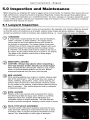
5.1 Lanyard Inspection
When inspecting lanyards, begin at one end and work to the opposite end. Slowly rotate the lanyard
so that the entire circumference is checked. Spliced ends require particular attention. Hardware
should be examined under procedures also detailed below, i.e., snap hooks, D-rings and thimbles.
O
O
HARDWARE
a. Snap hooks: Inspect closely for hook and eye distortions,
cracks, corrosion, or pitted surfaces. The keeper (latch)
should seat into the nose without binding and should not
be distorted or obstructed. The keeper spring should exert
sufficient force to firmly close the keeper. Keeper locks must
prevent the keeper from opening when the keeper closes.
b. Thimbles: The thimble must be firmly seated in the eye of
the splice, and the splice should have no loose or cut strands.
The edges of the thimble must be free of sharp edges,
distortion, or cracks.
WIRE ROPE LANYARD
CAUTION: Always wear gloves when inspecting a
wire rope lanyard; broken strands can cause injury!
While rotating the wire rope lanyard, watch for cuts, frayed
areas, or unusual wearing patterns on the wire. Broken
strands will separate from the body of the lanyard.
O
WEB LANYARD
While bending webbing over a pipe or mandrel, observe each
side of the web lanyard. This will reveal any cuts, snags, or
breaks. Swelling, discoloration, cracks, and/or charring are
obvious signs of chemical or heat damage. Observe closely
for any breaks in the stitching. Inspect lanyard warning flag for
signs of activation. Titan tubular lanyards must be measured
to determine activation.
ROPE LANYARD
Rotation of the rope lanyard while inspecting from end-toend will bring to light any fuzzy, worn, broken or cut fibers.
Weakened areas from extreme loads will appear as a
noticeable change in original diameter. The rope diameter
should be uniform throughout, following a short break-in period.
C)
PACK TYPE SHOCK ABSORBER
-
The outer portion of the pack should be examined for burn
holes and tears. Stitching on areas where the pack is sewn
to D-rings, belts, or lanyards should be examined for loose
strands, rips, deterioration or other signs of activation.
8
User Instructions - English
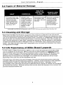
5.2 Types of Material Damage
HEAT
CHEMICAL
In excessive heat, rope/
webbing becomes brittle
and has a shriveled
brownish appearance.
Fibers will break when
flexed. Should not be
used above 180°F.
Change in color
usually appearing as
a brownish smear or
smudge. Transverse
cracks when rope/
webbing is bent over
a mandrel. Loss of
elasticity in rope/
webbing.
MOLTEN
METAL OR PAINTS AND
SOLVENTS
FLAME
Rope/webbing strands
fuse together. Hard
shiny spots. Hard and
brittle feel.
Paint which penetrates
and dries restricts
movement of fibers.
Drying agents and
solvents in some
paints will appear as
chemical damage.
Contact Miller Technical Service Department at 800-873-5242 if you have any questions about the above chart.
5.3 Cleaning and Storage
Basic care of all Miller Fall Protection equipment will prolong the durable life of the unit and will
contribute toward the performance of its vital safety function. Proper storage and maintenance after
use are as important as cleansing the equipment of dirt, corrosives, or contaminants. Storage areas
should be clean, dry and free of exposure to fumes or corrosive elements. Wipe off all surface dirt
with a sponge dampened in plain water. Squeeze the sponge dry. Dip the sponge in a mild solution
of water and commercial soap or detergent. Work up a thick lather, with a vigorous back and forth
motion. Then wipe dry with a clean cloth. Hang freely to dry, but away from excessive heat, steam,
or long periods of sunlight.
5.4 Life Expectancy of Miller Brand Lanyards
It is the position of Miller Fall Protection (MFP) to use a 5-year life expectancy from date of first
use as a guideline on all lanyards. MFP provides this recommendation as a aeneral guideline,
and is not to be used in lieu of the lanyard inspection section of this manual. This guideline only
applies to product exhibiting no visual damage and that has not been exposed to chemicals,
abnormal heat, or excessive ultra-violet light. It is possible that the equipment will last longer
depending on the care and use the equipment may see.
Following these instructions may still necessitate removing the lanyard from service prior to the
expiration of the five-year life expectancy guideline. Likewise, proper adherence to the inspection
and maintenance criteria may extend the useful life beyond five years. Ultimately, it is the
responsibility of the authorized person/user to determine when a lanyard is unfit for use and should
be removed from service. Products removed from service should be disposed of in a manner that
prevents inadvertent further use.
9
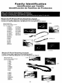
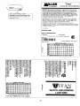
Family Identification
Identification par Famille
Identificacion de Familias de Productos
MILLER SHOCK-ABSORBING LANYARDS
CORDES D'AMARRAGE A ABSORBEUR D'ENERGIE
CUERDAS DE SEGURIDAD MILLER CON AMORTIGUACION DE IMPACTO MILLER
Manyard & HP Manyard Shock-Absorbing Lanyards
Cordes d'amarrage a absorbeur d'energie Manyard et HP Manyard
Cuerdas de seguridad Manyard y HP Manyard con amortiguacion de impacto
Base Model ifs:
Numeros des modeles de base:
Nem. de modelo base:
216WLS
219WRS
219WRXS
233WRS
233WLS
233WRXS
231 WRS
231WRXS
232WLS
266WRS
216W0
219W0
231W0
232W0
266W0
266WOR
216TWLS
219TWRS
233TWLS
233TWRS
231TWRS
232TVVLS
266TWLS
266TWRS
Manyard II Shock-Absorbing Lanyards
Cordes d'amarrage a absorbeur d'energie Manyard II
Cuerdas de seguridad Manyard II con amortiguaci6n de impacto
Base Model #'s:
Numeros des modeles de base:
NOM. de modelo base:
216M
216MD
219M
219MD
233M
219MRX
233MRS
231M
232M
232M
216M0
219M0
231 M0
232M0
233MORS
266M0
266MOR
24
219M
StretchStop Lanyards with SofStop Shock Absorber
Cordes d'amarrage StretchStop a absorbeur d'energie SofStop
Cuerdas de seguridad StretchStop con amortiguador de impacto SofStop
Base Model WS:
Numeros des modeles de base:
NOm. de modelo base:
8798RSS
8798SS
913RSS
913SS
8798SS
8798RSS
Lanyards with SofStop Shock Absorber and
HP Lanyards with SofStop Shock Absorber
Cordes d'amarrage a absorbeur d'energie SofStop
et cordes d'amarrage HP a absorbeur d'6nergie SofStop
Cuerdas de seguridad con amortiguador de impacto SofStop
y cuerdas de seguridad HP con amortiguador de impacto SofStop
Base Model #'s:
910WLS
Numeros des modeles de base:
Num. de modelo base:
910WLS
913K
913WLS
922WRS
928LS
8798
8798K
8798KR
8798R
8878
901 RLS
903RLS
907K
907LS
907NLS
940WLS
980WLS
940K
947K
910TVVLS
913TWLS
922TWRS
8798T
8798TR
8878T
8878TR
901RLS
913 WLS
907NLS
8878-6R
25
MILLER TIE-BACK LANYARDS
CORDES D'AMARRAGE DOUBLES MILLER
CUERDAS DE SEGURIDAD MILLER CON AMARRE POSTERIOR
BackBiter Tie-Back Lanyards with SofStop Shock Absorber
Cordes d'amarrage doubles BackBiter a absorbeur d'6nergie SofStop
Cuerdas de seguridad con amarre posterior BackBiter y amortiguador de impacto SofStop
Base Model ifs:
Numeros des modeles de base:
%tn. de modelo base:
8798B
8798BD
913B
913BD
940B
pigr
3B
8798B
MILLER POSITIONING AND RESTRAINT LANYARDS
CORDES D'AMARRAGE MILLER SERVANT AU POSITIONNEMENT ET A LA RETENUE
CUERDAS DE SEGURIDAD MILLER PARA POSICIONAMIENTO Y LIMITACION DE DESPLAZAMIENTO
Rope, Web and Wire Rope Lanyards
Cordes d'amarrage constituees par une corde, une sangle ou un cable metallique
Cuerdas de seguridad de fibra, tejidas y de alambre
Base Model gs:
Numeros des modeles de base:
NOm. de modelo base:
198RLS
201RLS
202RRXS
202RRS
203RLS
204RLS
210WLS
212WLS
213WLS
226WRS
235WLS
235WRS
207LS
207NLS
213WLS
MILLER 0 RING AND D RING EXTENSIONS
-
-
RALLONGES D'ANNEAU CIRCULAIRE ET D'ANNEAU EN D MILLER
EXTENSIONES CON ANILLO REDONDO Y CON ANILLO "D" DE MILLER
0-Ring Extension
D-Ring Extension
Rallonge d'anneau circulaire
Extension con anillo redondo
Rallonge d'anneau en D
Extension con anillo "D"
Base Model #:
Base Model #:
Modele de base n°:
Modelo base #.
Modele de base n°:
Modelo base #:
8928
8927
26
201RLS
TITAN SHOCK-ABSORBING LANYARDS
CORDES D'AMARRAGE A ABSORBEUR D'ENERGIE TITAN
CUERDAS DE SEGURIDAD TITAN CON AMORTIGUACION DE IMPACTO
Titan Pack-Type Shock-Absorbing Lanyards
Cordes d'amarrage a absorbeur d'energie a enveloppe compacte Titan
Cuerdas de seguridad Titan con amortiguacion de impacto tipo paquete
Base Model #'s:
Numeros des modeles de base:
Nam. de modelo base:
T6111
T6111
T6111V
T6112
T6112V
T6113
Titan Stretch Pack-Type Shock-Absorbing Lanyards
Cordes d'amarrage a absorbeur d'energie a enveloppe compacte a allongement Titan
Cuerdas de seguridad Titan estirables con amortiguacion de impacto tipo paquete
Base Model #'5:
Numeros des modeles de base:
Nam. de modelo base:
T6111SS
T6112SS
T6121SS
T6122SS
T6111 SS
Titan Tubular-Type Shock-Absorbing Lanyards
Cordes d'amarrage a absorbeur d'energie tubulaire Titan
Cuerdas de seguridad Titan tubulares con amortiguacion de impacto
Base Model #'s:
Numeros des modeles de base:
Nam. de modelo base:
T5113
T5011
T5111
T5112
T5113
T5121
T5122
Titan Stretch Tubular Built-In Shock-Absorbing Lanyards
Cordes d'amarrage a absorbeur d'energie integre tubulaire a allongement Titan
Cuerdas de seguridad Titan tubulares estirables con amortiguacion de impacto integrada
Base Model #'s:
Numeros des modeles de base:
Nam. de modelo base:
T5111SS
T5112SS
T5121SS
T5122SS
T5111SS
27
TITAN TIE-BACK LANYARDS
CORDES D'AMARRAGE DOUBLES TITAN
CUERDAS DE SEGURIDAD TITAN DE AMARRE POSTERIOR
Titan T-BAK Pack-Type Shock-Absorbing Tie-Back Lanyards
Cordes d'amarrage doubles a absorbeur d'energie a enveloppe compacte T-BAK Titan
Cuerdas de seguridad Titan T-BAK de amarre posterior con amortiguacion de impacto tipo paquete
Base Model #'s:
Numeros des modeles de base:
NOm. de modelo base:
T6111 TB
T6121TB
T6121TB
TITAN POSITIONING LANYARDS
CORDES D'AMARRAGE ET DE POSITIONNEMENT TITAN
CUERDAS DE SEGURIDAD TITAN PARA POSICIONAMIENTO
Titan Rope and Web Lanyards
Cordes d'amarrage Titan constituees par une corde et une sangle
Cuerdas de seguridad de fibra y tejidas
Base Model Ws:
Numeros des modeles de base:
NILim. de modelo base:
T9111R
T9111W
T9112R
T9112W
T9111R
All Miller lanyards and shock absorbers include this instruction manual. Special order and custom product model
numbers may not be listed. If there is any doubt as to whether this instruction manual applies to your particular
product, please contact Miller Fall Protection Technical Service Department at 1-800-873-5242.
Toutes les cordes d'amarrage et tour les absorbeurs d'energie Miller sont accompagnes de ce manuel d'utilisation.
Les numeros de modeles correspondant a des produits sur commande speciale et sur mesure peuvent ne pas etre
indique s ici. En cas de doute sur la validite de ce manuel d'utilisation pour votre produit particulier, veuillez contacter
le Service technique Miller au 1-800-873-5242.
Todas las cuerdas de seguridad y amortiguadores de impacto Miller incluyen este manual de instrucciones. No
se enumeran los nameros de productos de 6rdenes especiales y hechos a la orden. Si no sabe con seguridad si
este manual de instrucciones se aplica a su producto en particular, comuniquese con el Departamento de Servicio
Tecnico de Miller Fall Protection, o /lame al 1-800-873-5242.
28
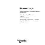
Parts Identification
Identification des Pieces
Identificacion de Piezas
Pack-Type Shock Absorber
Absorbeur (Margie é enveloppe compacte
AmortiguaciOn de impacto tipo paquete
Length Adjustment
Reglage de longueur
Ajuste de la longitud
0-Ring for Attachment of Retractable
Choke-through Loop
Anneau circulaire pour fixation du cordage a retraction
Anneau de serrage par etranglement
Anillo o para el accesorio de retractable
Mediante una lazada corrediza
Warning Flag
Indicateur de chute
Indicador de advertencia
Rebar Hook
Crochet pelican
Gancho .elicano
BackBiter 5K Snaphook
Crochet rnousgueton BackBiter 5K
Gancho de resorte BackBiter 5K
Snaphook
Crochet rnousqueton
Gancho de resorte
29
Product Labels
Etiquettes sur les Produits
Etiquetas de los Productos
Manyard & Lanyard Product Label
Etiquette sur corde d'amarrage et
produit Manyard
Etiqueta de producto de las cuerdas de seguridad Manyard
9
£
CINOS
VP
3Sfl ISHI4 AO
f
nva
IN
V
IN
NO 01610 HONDA
d
I'
Z
Date of Manufacture:
Expiration Date: See manual fa inspection.
I.
Compliance:
HA
Made :n USA
DO NOT REMOVE THIS LABEL.
'SSP 006
30610d ONILSMIHV
NOL103dSNI EICTA ivnNVIN 33S , 3100 N011V8IdX3
1300043 0038000 NO 0 0100-39 Z3OV snos IS N011331004
1103 5311113 731301000 34504001 343311 no 53150110 5390ss3 - 3 S30 Z3110S18
01301 3H10511400 503 31 SNVO 1108000 31 3388 53003012350 01101 300
10001853V3 no swou.onaism 531 831030535 Z3530 snos JI.t
,l3lAl3SS1.1113AV
'1410113310014 1103
LB957 Rev A
031118 NO3 11108000 5300100001501 140 1005 ,40
13 3018030 35 IS 31531140 01 0 SAAVHO 83001831 N3 8011503a 30300
0103305 ON 13 , 011DVA530 530 0103013 10 01000004 3103 503 5041.510094
3150318903 138 53001001151SN
■
Sill 35511193S 03930
VI3N3183ACIV
030330 SI 10ni3v43 NO11011HISNI
AI 00117310114 1101 8311145 1301500 H1030 HO AHOPNI sn0I035 NI
110535 01003 OS 00 01 3551103
034001101 39 15nv4 10340c11H5 AO 313111V
1.3110000 01011411/1 031100110 SNO113051SNI S 93801303014014 :0NiNu0ivt
03133130 SI 3004300 INV II 0311035 100011 380839 51139 050 S35530811 NO 501118 - 0 01 001030000 343
ION 1504', 144 , rs
.1)143141 000 00141030001 SONIN3d0 3100 FILM S0100H0V05
Model/Size:
0 5338030 05 , 3 S33151030 001 38090 531410100044031 HO 505055
•83303805 35100590 HO 4111VHS 14001003 0143805NVL3 010110 ION 00 05015011 351 30 510531
■
WON:
031015 3111 0001439 3 DNVISIO 00 553103 ' 40 .L1 II 9 0 503 050110 15043133Sn
111111111111111111111 11111
10 , e2 41191 1333 XIS NVH1
35041 ION JO 33501510 1101 334111011131X041 0 110110 01 0500 50 43 015
015e , 591 000
idoddns
-4
3190 000 -319110d13043 3910540 SINIOO 30015105050 ONO S801330000
,
1 - 500 - 173 - 5242
PAT 4 2535 44
0 P . N.5350370
ONINEIVM
LB951 REV .A
DO NOT REMOVE THIS TAG
ATTACH THIS END TO HARNESS
CAUTION: INSPECT BEFORE EACH USE
Material:
Capacity:
CSA Class:
Contact Miller Fall Protection if
instruction manual is needed. Max.
Arrest Force 900 lbs.; Max. Flee Fall
Distance of not more than 6-ft.: Max.
Extension 3'-6 - beyond stated length.
Remove from service if product has
been subject to a fall.
This variable label is included on all
Manyard and Manyard II Shock-Absorbing Lanyards.
MILLER
by SPERIPIN
MANYARD
SHOCK-ABSORBING LANYARD
30
Celle etiquette sur laquelle les inscriptions varient est apposee sur les cordes
d'amarrage a absorbeur d'Onergie
Manyard et Manyard II.
Esta etiqueta variable se incluye en
todas las cuerdas de seguridad Manyard
y Manyard II con amortiguacien de
impact o.
S
t,
E
Z
L
V
OS
asn Isuu
NA
F
d
V
N
FIN
F
AO 3160 NO GINO 143Nrid
S111 005 33800 ON0S3EldV
ri011:91StIl 200 1008810
3.11,1
.U ∎ 13M
631 Id I
11114 d1.1
•
338 -0160 IJOIlV61303
' I 34,
r,01 MCI, I 131 4 •
'
•••
iorr, s
••
■ ••• -
I830 -IS`1 , 18388
•.'
IN IS •S IiN 1.4 •
I -I, IJIISYS530 Sit .
•
•
, in Ii7NYZ MItJ
.
VION i
,
■ 83608
ONINHVAN
5
0
Z
L
V
OW
tiSs,
AE
Vd
l'INV
F
NA
asn isuu 10 alVO NO 01E10 H3Nfld
asn
5353 3801311 133dSNI
Nounvo
1 3150
otAir48810
IH.LON31\1300111
'221 OLE ,111OVE11/0
66 - L'ESZZ VSO 005'9061 2250
M00J
ISHV 65EZ IONS
'8000
DO NOT REMOVE THIS TAG
ATTACH THIS END TO HARNESS
N0113335NI 803100202 335 '3100 N0113781dX3
vsn 331N1 303/11
snon 30,3310t,
13113331131133,01/ Nr, 3103,43
3,1 33,131Z31SVINCIS 11104.041 3013O no S3AV139 saunss,a 333 ,nosiu
3nD,E1234,
snon gno
1131308d 3, 033,
,
CAUTION. INSPECT BEFORE EACH USE
mILLER
1N30135511H3AS
zaA ,
by SPERIPN
-IvriNall
331113/ 4400 311331/CO 3330,331313N1
NOG 33108d
33130341 33 IS A,,••• V, 33,30 S330,3133 ,m,s,1,1 3333d
MANYARD II
0,373,1 ON 13 0113VdS33 333 01,3013 , 01,3001, 3133 NO0 3VISIA0/41d
313,31,3V1133 s, 3s.n33s 33333
VION311,13ACIV
33333/4 31 TOW,/ Nryion.sly
SA 33 3 113/ 1,11.0D 14,33
SHOCK-ABSORBING LANYARD
1,1333 ills
00 V., IONINEIVM
• 3011,0, ••003en5
N
3,,
031333NO3 313
ION 111110 S.M.,. • •••• •••
5331110 • •
33 x•115115 3.
33,311 3333,33,131 SO 3NSVd3
OD ci clu,r,, /Am, 1.014
133J XIS NI,11
, O4
OO1SV 01 33 , 33 , N ,
sm.n3,104
V ow> 3301033NOS
a +100313 V 3011 43108d 11V3 dOd casn
ONINHVAA
DO NOT REMOVE THIS TAG
CAUTION. INSPECT BEFORE EACH USE
1 850,710201
MILLER
LANYARD
& HORIZONTAL or
VERTICAL LIFELINES
31
StretchStop, SofStop & BackBiter Product Label
Etiquette sur les produits StretchStop, SofStop
et BackBiter
Etiqueta de producto StretchStop, SofStop
y BackBiter
'SS3N1IVH 01/100H dIANS )IOVd 21351110513V )OOHS H3VIIV AlN0 •
'S3SS3II91VH NO SON121- 0 01 03133NNO3 39 ION is(3m
(unur9z) HDNI t NVHI 113011V1 SONIN3dO 31V9 HAM S)100H dVNS •
(•sql 009't 1e1 Petw eq Ismu mod eBetotpelV N811 00111.
= 90303 )4INJV 58W " 8'0 '05U. 30 11013V1 A.L33VS V NO3 SIN3E1
-391n0391 z09'9Z61 VHSO 13384 NO (NNW 'Sal 0001 lliOddllS 01318V
ONV 31811IMPIOD 38 isnw SINIOd 30V9OHONV ONV S910133NNO3 •
1333V3IMS 3AISVIJEW 210 &IVES 13VJA03 01 tonaotod MOAN ION °a •
11N3193/11(3513H Asolv1n039 HIIM 33NV091033V NI 140113310n3 11V3 3511 •
:ONINLIVM
SOFSTOP®
MILLER
This label is included on all SofStop,
StretchStop, and BackBiter products.
with the name variation.
Cette etiquette est apposee sur les
produits StretchStop, SofStop et
BackBiter; seul le nom vane.
Esta etiqueta se incluye en todos
los productos SofStop, StretchStop
y BackBiter, con la variacidn en el
nombre.
by SPERIRN
WARNING: MANUFACTURER'S INSTRUCTIONS SUPPLIED WITH THIS
PRODUCT AT TIME OF SHIPMENT MUST BE FOLLOWED. FAILURE TO DO
SO COULD RESULT IN SERIOUS INJURY OR DEATH.
ADVERTENCIA: DEBEN SEGUIRSE LAS INSTRUCCIONES DEL FABRICANTE PROVISTAS CON ESTE PRODUCTO AL MOMENT() DE DESPACHO.
EL NO HACERLO PUEDE RESULTAR EN LESIONES GRAVES 0 LA MUERTE.
AVERTISSEMENT: VOUS DEVEZ RESPECTER LES INSTRUCTIONS DU FABRICANT QUE VOUS AVEZ RECUES AVEC LE PRODUIT. DANS LE CAS CONTRAIRE. VOUS RISQUESZ DES BLESSURES GRAVES OU MEME LAMORT.
INSPECT BEFORE EACH USE
LB303 Rev. F I MFP9347502
'SS3NNVH 01 NOON •IVNSH3Vd 9138110013V )130145 NW/Le A1NO •
E3S8IIINVII NO S1NIN-C1 01 03133NNO3 38 ION
isnw (88,99) HONI 1 NVill 113091Y1SONIN3d0 31Y0 HIJM (0100H deNS •
laDVA$DS 341SVI8V 910 WAVHS LIVINGS 0110110083 MOTIV ION 00 •
'S1N3M3H111031111101V1110311 01 NOLL3310Nd 11V3 DIN •
('84 1009'5 Jet
eq Pew Med
efIeloqouy :•sce wer . •aJoA WeNV xew "3 9) 'OILL 30 11010V3 1.1.33VS V 9103
si8383190098 203956t VH801338110 HMV '881 oars iaothins 01 318V
(WV 31801M11103 38 1511111 8111103 30V/10H3NV ENV 8/10133NNO3 •
1.51111'13 930 wrou0(v8 V 01 0911811 38 111W 11V3 33913
3H1 3113104 arm My 1110) 1191 OW 01 (84INN) 1181 14t N33841313 SHOWN lYHL
83)111041v atm ao One. L1 '14 9 NVILL 83.1x980 30 Tiva 3383 V tli loarens
seal t10 (019.080 lam
SI
erammam 83880m v 9103 CL :91.011
NOLL331D91d 11Y3 0I3103d8 OPAL 9103 035133NION3 SI ionaoad 51111 •
:ONINPNM
13}514
This label is included on all SofStop
Max, StretchStop Max, and BackBiter
Max products, with the name variation.
Cette etiquette est apposee sur les
produits StretchStop Max, SofStop
Max et BackBiter Max; seul le nom
vane.
Esta marca se incluye en todos los
productos SofStop Max, StretchStop
Max y BackBiter Max, con la variaGlen en at nombre.
LANYARD
with SOFSTOP
WARNING: MANUFACTURER'S INSTRUCTIONS SUPPLIED WITH THIS PRODUCT AT
TIME OF SHIPMENT MUST BE FOLLOWED. FAILURE TO DO SO COULD RESULT IN
SERIOUS INJURY OR DEATH.
ADVERTENCIA: DEBEN SEGUIRSE LAS INSTRUCCIONES DEL FABRICANTE PROVISTAS CON ESTE PRODUCTO AL MOMENTO DE DESPACHO. EL NO HACERLO
PUEDE RESULTAR EN LESIONES GRAVES 0 LA MUERTE.
AVERTISSEMENT: VOUS DEVEZ RESPECTER LES INSTRUCTIONS DU FABRICANT
QUE VOUS AVEZ RECUES AVEC LE PRODUIT. DANE LE CAS CONTRAIRE. VOUS
RISQUESZ DES BLESSURES GRAVES OU MEME LAMORT.
INSPECT BEFORE EACH USE
LOON Roc C / 1AFP7294591
32
1
Date of Manufacture:
Expiration Date: See manual for inspection.
Compliance:
Made in USA
Contact Miller Fall Protection if
instruction manual is needed. Max.
Arrest Force 900 lbs.; Max. Free Fall
Distance of not more than 6-ft.; Max.
Extension 3'-6" beyond stated length.
Remove f rom service if product has
been subject to a fall.
This variable label is included on all Miller shock absorber
pack products.
Cette etiquette sur laquelle les inscriptions varient est apposee
sur les absorbeurs d'energie a enveloppe compacte Miller.
Esta etiqueta variable se incluye en todos los productos Miller
de amortiguador de impacto.
LB956 Rev A.
Model/Size:
CSA Class:
WOO:
II 1111 11 1 111 11111111 11 1 111EI
Inspection No.:
Mate ial:
Capacity:
NAPLci IUN tiN.II3
YR
/FMAM JJAS 0 N D
Le mousqueton attache a I extremde de la
El gancho de mosqueton achunto at extremo
longe pent etre uhlme pour former des
de la cuerda ha lido disenado pare pernstir la
boucles d etranglement
N Wiese, pas les mousguelons standard
formamon de los bucles de estrangularmento
No utilaarest Poo de conexion estanclar que
no hen lido chsenados especificamente pars
arils n ont pas ete concres pour ce type
V application. L inobervarron de cel
averbssernent risque d enrrainer des
2
3
4
5
hlessures graves ou la mort
Vole figure au verso.
L ocrOYNEFTWillrgirdIEL.
♦
AVERTISSEM ENT!
este USO. La no obser vanica de esta
aelvertencia puede causar serial Issiones o la
muerte
Conyulte la figura en el revers°
ADVERTENC IA!
100.
BackBiter Tie-Back Lanyards include this
warning label on the 5K snap-hook end of the
lanyard.
Cette etiquette de mice en garde est apposee
sur l'extremite cote crochet mousqueton 5K
des cordes d'amarrage doubles BackBiter.
Las cuerdas de seguridad de amarre posterior
BackBiter incluyen esta etiqueta de advertencia en el extremo del gancho de resorte 5K
de la cuerda.
TYPICAL INSTALLATION
The snaphook attached to this end of the lanyard
is designed to permit connection hack to the
integral lanyard in a choking fashion .
Do not attempt this type of a connection with
standard snaphooks which are not specifically
designed for such a connection. Failure to follow
this warning may cause serious injury or death
AkILLER
33
10
Titan'
MILLER
by SPERIRN
Lanyards and Lifelines
WARNING: Mannfacnners ins-unctions supplied with this product at
the time of shipment must be followed failure to do so may result in
seri.s injury or death. lisped before each use in accordance to the
mannfactruer's instructions stippled at the time of shipment. Avoid
contact with sharp or abrasive surfaces. Connectors and anchorage
points !mist be compatible and able to support 5000 lbs. Thisproduct
is designed for positioning only and must be used in conjunction with a
shock-absorber when used for fall arrest. Contact Miller Fall
Protection if instioction manual's needed.
Titan Lanyard Product Label
Etiquette sur corde d'amarrage Than
Etiqueta de producto de cuerdas de
seguridad Titan
Advertissernent: Vous deves respecter les instructions du fahricant
rpm yours avez recites avec to produit. Dare la cas contraire. vote
[mitre, de blessm es graces 011 men. la mon. Contaoez Miller Fall
Protection si volts aye, desoin dun nouveau manual.
Advertencia: Lieber] segnirse las instrucciones del fahricante
pi ovistes con este producto - el no Itacerlo 'merle resultar err lesiones
graves o la muerte. Si se requiere el manual de instmcciones consulte
con Miller Fall Protection.
ompliance:
Model/Length:
Date of Manufacture:
Capacity:
CSA Class:
Expiration Date: See manual for inspection
MI
IIIIII III III IIIIIIIII
Inspection No.:
DO NOT REMOVE THIS LABEL.
INSPECTION GRID
9' ,sad ZOt91
YR J
F
A
N
2
3
4
MARK GRID ON
34
J J A S
DATE OF FIRST USE
Date of Manufacture:
Expiration Date: See manual fa inspection.
Compliance:
Titan Pack-Type Lanyard Product Label
(markings located on shock absorber pack)
Etiquette sur les Gorden; d'arnarrage 6 absorbers
d'energle it enveloppe cornpacte Titan
Etiqueta de producto de as cuerdas de segurick d
Titan tipo paquete
'8931121VH 01900H dYNS )43Vd 6313210813V )130HS 11311119 A1N° •
'838113N/NH NO SONIU'O 01 03103NNO3 38 ION ism
6100612) HON! I NV14193°9'0 SONIN3d0 31VO HIVA 5)10014 dYNS •
(' 591 009'3 JOJ P014/ 00 islim 9110d eelbelloilV !lie! oarri
- ewes leans sew " 15•5) 'OKI. dO 21010Vi Al3AVS V BOA SIN304
-321101039 3081361 VH80 13391 190 (NU3) '891 0001 1schians 01 319V
ONV 3181.1.VdM00 39 ism SINIOd 30V110HONV ONY 890103NNO3 •
'5233VMM 3AISVIRIV NO dNVNS 19V1NO3 0113400214 MOTIV ION 00 •
'61N363/60039 Ati101Y1119311 KUM 33NY/39033V NI NO113310E4 TWd asn •
:ONINVVM
Made in USA
Contact Miller Fall Protection if
instruction manual is needed. Max.
Arrest Force 900 lbs.; Max. Flee Fall
Distance of not more than 6-ft.; Max.
Extension Y-6" beyond stated length.
Remove from service if product has
been subject to a fall.
LB956 Rev A.
BAIC
MILLE!'
WARNING: MANUFACTURER'S INSTRUCTIONS SUPPLIED WITH THIS
PRODUCT AT TIME OF SHIPMENT MUST BE FOLLOWED. FAILURE TO DO
SO COULD RESULT IN SERIOUS INJURY OR DEATH.
ADVERTENCIA: DEBEN SEGUIRSE LAS INSTRUCCIONES DEL FABRICANTE
PROVISTAS CON ESTE PRODUCTO AL MOMENTO DE DESPACHO. El. NO
HACERLO PUEDE RESULTAR EN LESIONES GRAVES 0 LA MUERTE.
AVERTISSEMENT: VOUS DEVEZ RESPECTER LES INSTRUCTIONS DU FABRICANT CIUE VOUS AVEZ RECUES AVEC LE PRODUIT. DANS LE CAS CONTRAIRE. VOUS RISOUESZ DES BLESSURES GRAVES Oil MEME LAMORT.
Model/Size:
CSA Class:
WON:
INSPECT BEFORE EACH USE
1.8557 Rev. C / MFP9346031
111111111111111111111111111
Inspection No.:
Mate ia :
Capacity:
114.714uRiu
iEllOCZEZEICEICIZI
'SS3NIIVH 01900H dYNS )IDVd 9313/JOSSV MOONS H3VLLV AIN° •
'1331183NHVII NO SONRI-0 01 03103NNO3 38 ION 18094
(unarsz) HONI I NV141113109V1 SONIN3d0 3110 HIM £0100H dYNS •
oes's Ass Pew se ;urs wins soluonsuv :•841 met
scrod teeny 9166 "E.° 'OPAL dO 9010VA A134V8 V1104 SIN31/1
-atanoas certain YHSO 13391 NO (Nnin) *sin eee's itiosAns cu. 318V
ONY 319LLY0100 38 Isms SINIOd 30V110H3NV ONV 8110L23N1100 •
•saavians 3A18VN9Y NO di1V16113V1/103 01.100009d M011V ION 00 •
'&M39391°0311 ANOIY10O3N HUM aaavaliosav NI NOU.33102IdlTi4 asn •
Titan®
Shock Absorber
MILLER
by SPERIFIN
WARNING: MANUFACTURER'S INSTRUCTIONS SUPPLIED WITH THIS
PRODUCT AT TIME OF SHIPMENT MUST BE FOLLOWED. FAILURE TO DO SO
COULD RESULT IN SERIOUS INJURY OR DEATH.
ADVERTENCIA: DEBEN SEGUIRSE LAS INSTRUCCIONES DEL FABRICANTE
PROVISTAS CON ESTE PRODUCTO AL MOMENTO DE DESPACHO. EL NO
HACERLO PUEDE RESULTAR EN LESIONES GRAVES 0 LA MUERTE.
AVERTISSEMENT: VOUS DEVEZ RESPECTER LES INSTRUCTIONS DU FARMCANT (WE VOUS AVEZ RECUES AVEC LE PRODUIT. DANS LE CAS CONTRAIRE VOUS RISQUESZ DES BLESSURES GRAVES OU MEME LAMORT.
INSPECT BEFORE EACH USE
1.8390 Rev. E / 94-9346022
35
nunmumml
FIIII1111•111111111•1
fill11111•1111M
P
111•Ell• MIN
DO NOT
•
groVi THIS LABEL.
This variable label is included
on all Titan shock absorber pack
products.
Cette etiquette sur laquelle les
inscriptions varient est apposee
sur les absorbeurs d'energie a
enveloppe compacte Titan.
Esta etiqueta variable se incluye
en todos los productos Titan de
amortiguador de impacto.
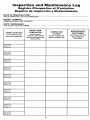
Inspection and Maintenance Log
Registre D'inspection et D'entretien
Registro de InspecciOn y Mantenimiento
DATE OF MANUFACTURE:
DATE DE FABRICATION / FECHA DE FABRICACION
MODEL NUMBER:
NUMERO DE MODELE / NOM. DE MODELO
DATE PURCHASED:
DATE D'ACHAT / FECHA DE COMPRA
INSPECTION DATE
DATE D'INSPECTION
FECHA DE INSPECCION
INSPECTION
ITEMS NOTED
CORRECTIVE
ACTION
POINTS NOTES
LORS DE L'INSPECTION
ACTION CORRECTIVE
PUNTOS DE INSPECCION
RELEVANTES
MEDIDA CORRECTIVA
Approved by
Approuve par:
Aprobado por.
Approved by:
Approuve par:
Aprobado por:
Approved by
Approuve par:
Aprobado por:
Approved by
Approuve par .
Aprobad:
Approved by:
Approuve par:
Aprobado por:
Approved by:
Approuve par:
Aprobado pc,
Approved by'.
Approuve par:
Aprobado por:
Approved by:
Approuve par,
Aprobado por:
Approved by:
Approuve par:
Aprobado per
Approved by
Approuve par:
Aprobado por:
36
MAINTENANCE
PERFORMED
ENTRETIEN EFFECTUE
MANTENIMIENTO
REALIZADO
MILLER® FALL PROTECTION PRODUCTS
TOTAL SATISFACTION ASSURANCE
At Miller Fall Protection, we have been providing quality Miller brand fall protection
equipment to millions of workers worldwide since 1945.
LIMITED LIFETIME WARRANTY
BACKED BY OVER 60 YEARS IN THE FALL PROTECTION BUSINESS
We sincerely believe that our fall protection equipment is the best in the world.
Our products endure rigorous tests to ensure that the fall protection equipment you trust is manufactured
to the highest standards. Miller fall protection products are tested to withstand normal wear and tear,
but are not indestructible and can be damaged by misuse.
Our Limited Lifetime Warranty does not apply to normal wear and tear or abusive treatment of the product.
In the unlikely event that you should discover defects in either workmanship or materials,
under our Limited Lifetime Warranty, we will repair or replace the product at our expense.
If a replacement is necessary and your product is no longer available, a comparable product will be substituted.
Should a product issue surface, contact us at 800.873.5242.
Manufacturing specifications are subject to change without notice.
PRODUITS MILLER® FALL PROTECTION
ASSURANCE DE SATISFACTION TOTALE
Chez Miller Fall Protection, nous fournissons des equipements de protection contre les chutes de marque
Miller de quality a des millions de travailleurs dans le monde entier depuis 1945.
GARANTIE LIMITEE
A VIE
ASSUREE GRACE A PLUS DE 60 ANS PASSES DANS LE DOMAINE DE LA PROTECTION CONTRE LES CHUTES
Nous crayons sincerement que notre equipement de protection contre les chutes est le meilleur au monde. Nos
produits sont soumis a des tests rigoureux, afin d'assurer que les equipements de protection contre
les chutes dans lesquels vous avez confiance sont fabriques selon les normes les plus exigeantes.
Les produits de protection contre les chutes Miller sont soumis a des essais pour verifier qu'ils resistent a une usure
normale; ils ne sont cependant pas indestructibles et peuvent s'endommager en cas de mauvaise utilisation. Notre
garantie limitee a vie ne s'applique pas a l'usure normale ou a un usage abusif du produit.
Dans le cas peu probable ()C.' vous decouvririez des Waits, soft de fabrication, soit de materiau,
dans le cadre de notre garantie a vie, nous reparerons ou remplacerons le produit a nos frais.
En cas de remplacement, si votre produit n'est plus offert, vous recevrez un produit comparable.
En cas de probleme sur un produit, nous contacter au 800-873-5242.
Les caracteristiques de fabrication peuvent etre modifiees sans preavis.
PRODUCTOS ANTICAIDAS MILLER®
GARANTIA DE SATISFACCION TOTAL
En Miller Fall Protection, venimos suministrando desde 1945 los equipos de protecciOn anticaidas
con la calidad Miller a millones de trabajadores en todo el mundo.
GARANTIA LIMITADA DE POR VIDA
NOS RESPALDAN MAS DE 60 AROS EN LA FABRICACION DE EQUIPO ANTICAIDAS
Sinceramente creemos que su equipo de protection contra caidas es el mejor del mundo. Nuestros productos resisten
rigurosas pruebas pars garantizar que el equipo de protection contra caidas en el que usted confia este fabricado de
conformidad con las normas mas elevadas. Los productos anticaidas Miller son sometidos a pruebas para que resistan el
desgaste normal, pero no son indestructibles y su incorrecta utifizacion puede danarlos.
Nuestra Garantia limitada de par vida no se aplica al desgaste normal ni al maltrato del producto.
En el poco probable caso de que usted descubriera defectos de mano de obra o materiales, por nuestra Garantia limitada de por vida, repararemos o sustituiremos el producto por cuenta nuestra. Si un reemplazo es necesario y nuestro
producto ya no esta disponible, se lo sustituiremos por otro comparable.
En caso de que surja un problems con el producto, contactenos al 800.873.5242.
Las especificaciones de fabricaciOn estan sujetas a modificaciones sin previo aviso.
37
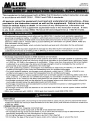
1264 REV A
MFP9720136
This supplement is being issued with all Miller Fall Protection product instruction manuals
in accordance with ANSI Z359.1, Z359.3 and Z359.4 standards.
All persons using this equipment must read and understand all instructions—those
provided in the instruction manual as well as this supplement. Failure to do so may
result in serious injury or death. In the event of any discrepancies, information and
warnings provided in this supplement supersede those in the instruction manual. If there
is any doubt, please contact Miller Technical Services Department at 1-800-873-5242.
GENERAL REQUIREMENTS
• All authorized persons/users must reference the ANSI Z359.1 standard and applicable regulations
governing occupational safety. In addition, authorized persons/users of positioning and travel restraint
equipment must reference ANSI Z359.3 and authorized persons/users of rescue equipment must
reference ANSI Z359.4. Please refer to product labeling for information on specific OSHA, ANSI and
CSA standards met by product.
• Never remove product labels, which include important warnings and information for the authorized
person/user.
• Any equipment that has been subjected to damage as described by the manufacturer or has been
subjected to the forces of arresting a fall or affecting a rescue must be removed from service.
ANCHORAGE REQUIREMENTS
• Anchorage requirements based on ANSI standards are as follows:
• Anchorages selected for personal fall arrest systems shall have a strength capable of sustaining static
loads of at least two times the maximum arrest force permitted on the system when certification exists,
or 5,000 lbs. (22.2kN) in the absence of certification. When more than one personal fall arrest system
is attached to an anchorage, the above anchorage strengths must be multiplied by the number of
personal fall arrest systems attached to the anchorage.
• For work positioning systems, anchorages must withstand a static load of 3,000 lbs. (13.3kN) for noncertified anchorages or two times the foreseeable force for certified anchorages.
• For travel restraint systems, anchorages must withstand a static load of 1,000 lbs. (4.5kN) for noncertified anchorages or two times the foreseeable force for certified anchorages.
• Anchorages selected for rescue systems shall have a strength capable of sustaining static loads of at
least 3,100 lbs. (13.9kN) for non-certified anchorages, for connection of rescue system only, or meet a
safety factor of 5:1 based on the static load placed on the system for certified anchorages.
• Anchorage connectors shall not be attached to anchorages where such attachment would reduce the
anchorage strength below the applicable levels set forth above.
• Anchorage connections shall be stabilized to prevent unwanted movement or disengagement of the
system from the anchorage.
• Anchorage connectors shall be attached to no more than one PFAS or rescue system unless certified
for such purpose.
• Miller steel carabiners with 3,600 lb. (16kN) gate load capacity meet ANSI Z359.1(07).
A\ WARNINGS
BODY WEAR
• Harnesses equipped with a front D-ring for fall arrest shall be used only as part of a personal fall arrest
system that limits the maximum free fall distance to two feet (0.6m) and limits the maximum arrest force
to 900 lbs. (4kN).
CONNECTING DEVICES
• For lanyards with two, integrally connected legs:
• Connect only the center snap hook to the fall arrest attachment element.
• Do not attach the leg of the lanyard which is not in use to the harness except to attachment points
specifically designated by the manufacturer for this purpose.
• Do not rig the lanyard to create more than a six-foot (1.8m) free fall.
• Do not allow the legs of the lanyard to pass under arms, between legs or around the neck.
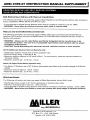
ANSI Z359-07 INSTRUCTION MANUAL SUPPLEMENT I
ASSISTED-RESCUE AND SELF-RESCUE SYSTEMS,
SUBSYSTEMS AND COMPONENTS
Self-Retracting Lifelines with Rescue Capabilities
The following information and warnings apply to Miller MightEvac Self-Retracting Lifelines with emergency
rescue capabilities (MR50, MR100 and MR130 units).
• Force required to operate rescue features when device is loaded to capacity is 22 lbs. (98N).
• WARNING: Never allow the lifeline to become slack while in rescue mode.
Rescue and Controlled Descent Devices
The following information and warnings apply to Miller SafEscape Controlled Descent/Self-Rescue
Systems (AG10 devices and kits) and Miller Series 70 Universal Rescue Systems (all base model 70
devices and systems).
• WARNING: Always use the rope lifeline specifically designated by the manufacturer to be
used with the system. The use of an incompatible rope lifeline could interfere with the proper
functioning of the system.
• CAUTION: Avoid descending into electrical, thermal, chemical sources or other hazards.
AG10 SafeEscape (Descent Device) Systems only
• SafeEscape Systems include 3/8" (9.5mm) polyester rope.
• Descent energy rating: 5,530,000 ft.-lbs.
• Maximum descent distance is 436 yards (400m) For two persons, maximum descent distance is
109 yards (100m).
• Maximum descent rate: 2.5 ft./sec. (.7m/s)
Series 70 (Rope Tackle Block) Systems only
• The Series 70 Systems use a 3/8" (9.5mm) kernmantle rope lifeline with a tensile strength of 5,600 lbs.
(25kN).
• Maximum descent distance: 500 ft. (152m)
• Maximum descent rate: 2.5 ft./sec. (.7m/s)
Winches/Hoists
The following information and warnings apply to Miller ManHandler Hoists (8442 units).
•
•
•
•
ManHandler hoists contain 3/16" (5mm) galvanized or stainless steel cable.
Maximum working length of load line: 100 ft. (30.5m)
Force required to operate rescue features when device is loaded to maximum capacity: 22 lbs. (98N)
WARNING: Never allow the lifeline to come into contact with sharp edges or abrasive surfaces.
AILLEA
by SPERIAN
Sperian Fall Protection, Inc.
P.O. Box 271, 1345 15th Street
Franklin, PA 16323 USA
MILLER°
by SPERIAN
Toll Free: 800.873.5242
Fax: 800.892.4078
Download this manual at: www.millerfallprotection.com
Telechargez ce manuel a l'adresse: www.millerfallprotection.com
Puede bajar por Internet este manual en: www.millerfallprotection.com
Sperian Fall Protection, Inc.
P.O. Box 271, 1345 15th Street
Franklin, PA 16323 USA