1
Operation
and Maintenance
3681036666
Manual
GARAGE
TABLE OF CONTENTS
Warranty
Information
Safety Information
Safety Features
Important
...................
Pre-lnstallation
Instructions
Checklist
Programming
the Remote
lightbulb
Wiring
Diagram
Guide
Control
...............
.............
Views .....
............................
3
4-6
7-8
........................
Parts Lists and Exploded
Accessories
.......
and lens .............
Maintenance
Troubleshooting
3
..............
..........................
Scheduled
3
.........................
Adjustments
Installing
2
.....................
Installation
INTELLICODE ®
REMOTE CONTROL AND SERIESII
COMPLETE WiTH
......
8
9
10
10-11
12
12 -13
14
ELECTRONICS
For 7' 6" Doors. Extension Kit is available
for 8' Doors
Included Wall Control MUST be installed prior to Operation
of this Garage Door Operator.
Safe-T-Beam ® Safety Reverse System Must be installed and
the Force Controls MUST be Properly Set to close door.
This Equipment meets or exceeds all Federal, State and UL 325
Safety Requirements.
Having Difficulty?
Need Help?
Please call us: 1-800-35-GENIE (354-3643)
www.geniecompany.com
Please have Model information ready when calling.
THE GENIE COMPANY LiMiTED WARRANTY
What is covered?
Date Purchased
Any defect in material and product workmanship from personal, normal
household use in accordance with the Owner's Manual.
For how long?
MODEL 2020LSeries... 10 years on motor and 2 years on all other parts.
/
/
Serial Number*
Operator Model*
Dealer Name
DealerAddress
Who gets the warranty?
This warranty is limited to the consumer who originally purchased
the product.
Geographic
Pleasenote the following information,soit is available if you
need to call us.
City
State / Zip
scope:
This warranty applies only to units installed and operated within the country
where they were purchased.
eeSerial Number is located on the Power Head, inside
the Light Cover.
Limitations:
IMPLIEDWARRANTIES,INCLUDINGTHOSEOF FITNESSFORA PARTICULAR
PURPOSEAND
MERCHANTABILITY
(AN UNWRITTENWARRANTYTHAT THE
PRODUCTISFITFORORDINARYUSE),ARELIMITEDTO ONEYEARFROMTHE
DATEOF PURCHASE.
GENIEWILL NOT PAY FOR:LOSSOF TIME;
INCONVENIENCE;
LOSSOF USEOF YOURGENIEPRODUCTORPROPERTY
DAMAGECAUSEDBYYOURGENIEPRODUCTORITSFAILURETO WORK;ANY
SPECIAL,INCIDENTALORCONSEQUENTIAL
DAMAGES;OR ANYDAMAGES
RESULTINGFROMMISUSEORMODIFICATIONOFYOURGENIEPRODUCT.
WK
YR
Serial/Mfg
P
I'_
No.
Some states and provinces do not allow limitations on how long an implied
warranty lasts or the exclusion of incidental or consequential damages, so the
above limitations or exclusions may not apply to you.
This warranty is the only one we will give on your Genie product, and it sets
forth all our responsibilities regarding your Genie product.There are no other
express warranties.
NOTE
State and province rights: This warranty gives you specific legal rights, and
you may also have other rights which vary from state to state andprovince to
province.
Pleasekeep original or photocopy of your sales receipt
with this manual for future reference shouldservice
ever be required.
How to get warranty
service:
To obtain warranty service for your Genie product, you must provide proof of
the date and place of purchase of the product.
INCLUDED IN THIS PACKAGE
Manual
1. Do=it-Yourself-Service.
Call the Genie Customer Servicetoll free at 1.800.354.3643to speak in
person to a trained Genie representative for assistance in diagnosing the
problem and arranging to supply you with the required parts for do-ityourself repairs.Trained service representatives are available Monday-Friday,
8:00 a.m.- 9:00 p.m., EasternTime, and on Saturday, 10:00a.m. to 7:00 p.m.,
EasternTime (subject to holidays) You may also get the information you
need at www.geniecompany.com.
2.Service
From Authorized
Dealers.
Youalsomayobtainwarrantyservicefrom Genieauthorizeddealersbycallingthe
GenieCustomerServiceat 1.800.354.3643
or byvisitingwww.geniecompony.com
beforeschedulingwarrantyservice.If warrantyserviceis providedbyan authorized
dealer,Geniewill provideallrequiredpartsunderwarrantyat no chargeto you, but
the dealersareindependentbusinesspeopleandmayrendera benchor servicecall
chargefor their services.Geniewill not reimburseyou or otherwiseberesponsiblefor
thosecharges.
Wesuggestthat you retainyouroriginalpackingmaterialin theevent we choose
to repairor replaceyour GenieProductand requestthat you shipit to us.Besureto
includeyour name,address,telephonenumber,proof of dateand placeof purchase
and adescriptionof the operating problem.After repairingor replacing,yourGenie
product,we will ship it to yourhomeat no costto you for partsand labor,but you will
haveto paya minimumof $S.00for shippingand handlingcharges.
1) Warranty Information
2) Pre Installation Checklist to be reviewed
prior to any assembly or installation
3) Necessary Adjustments
4) Programming Remote Devices
5) Maintenance and Troubleshooting
6) Parts Explosions
7) Accessory Order Form
8) Door Opener Association Safety and
Maintenance Brochure (DASMA)
Poster
9) Entrapment Warning Label- To be Adhered
in close proximity to wall control
1) Pictorial and step by step opener assembly
instructions
2) Pictorial and step by step opener installation
instructions
Yourchoiceof eitheroneof the above-describedserviceoptionsisyour exclusive
remedyunderthis warranty.
What
this warranty
does
not cover:
Thiswarrantydoesnotcoverbatteries(whichareconsideredreplaceableparts),
installation,commercialuse,defectsresultingfrom accidents,damagewhile intransit
to our servicelocationor damageresultingfrom alterations,misuseor abuse,lackof
propermaintenance,unauthorizedrepairor modificationof the product,affixingof
any attachmentnot providedwith the product, programmingof the RemoteControl
Devices,Safe-T-Beam
®adjustment/cleaning,staplesthrough wiring, pinchedor broken
wires,Carriagedisengaged,ForceControladjustments,door out of balance,broken
springsor cables,power outages,useof extensioncords,missingor damagedpartson
discounted,clearanced,final saleor tapedcartons,phantomoperations(labor is not
coveredif Openeris functioning properlywhile technicianis in garage),fire,flood,or
actsof God,or other failureto follow the Owner'sManual.
2
MARKED CLEARLY IN BOTH THE MANUAL
lAND POSTER ARE READ, UNDERSTOOD
FOLLOWED;
AND
Visit Our Website at: www.geniecompany.com
FORANSWERS:CALL1.800.354.3643
SAVE THESE INSTRUCTIONS
For Help, call 1=800-3S-GENIE or visit www.geniecompany.com
OVERVIEW
OF POTENTIAL
HAZARDS
Overhead doors are large, heavy objects that move with the help of springs under high tension and electric motors. Since moving objects, springs
under tension, and electric motors can causeinjuries, your safetyand the safety of others depend on you reading the information in this manual. If you
havequestions or do not understand the information presented, call The Genie Company. or your local GenieDistributor.
In this section, and those that follow, the words Danger, Warning
information. The word:
situation
and Caution
are used to emphasize
important safety
DANGER:
indicates an imminently hazardous
which, if not avoided, will result in death or serious injury.
WARNING:
indicates a potentially
hazardous situation
which, if not avoided, could result in death or serious injury.
CAUTION:
indicates a potentially
hazardous situation
which, if not avoided,
The word NOTE is used to indicate important steps to be followed
POTENTIAL HAZARD
damage.
or important considerations.
EFFECT
WARNING:
Could result in death
or serious injury,
may result in injury or property
PREVENTION
. Keep people clear of opening while door is moving.
o Do Not allow children to play with the door operator.
o Do Not operate a door that jams or one that has a broken spring.
MOVING DOOR
WARNING:
Could result in death
or serious injury.
oWhen replacing
moving parts.
oOperator
ELECTRICALSHOCK
WARNING:
Could result in death
or serious injury.
HIGH SPRINGTENSION
oTurn off power before removing
must be properly
2
3
4
5
6
7
8
cover.
grounded.
. Do Not try to remove, repair or adjust springs or anything to
which door spring parts are fastened, such as, wood blocks,
steel brackets, cables or other like items.
o Repairs and adjustments must be made by a trained door
system technician using proper tools and instructions.
MPORTANT INSTALLATION
NSTRUCTIONS
WARN IN G:
TO REDUCE THI RISK
OF SEVERE INJURY OR DEATH:
1
operator
cover, make sure wires are not pinched or near
SAFETY
FEATURES
Safe-T-Beam® (STB) Non-Contact
Reversing System
Places an invisible beam across door opening, that
reverses the door during down travel to the fully
open position if anything passesthrough beam.
READAND FOLLOW ALL SAFETY,INSTALLATIONAND OPERATION
INSTRUCTIONS.If you have any questions or do not understand
an instruction, call your authorized Genie installation professional.
Do Not install operator on an improperly balanced door. An
improperly balanced door could cause severe injury. Repairs and
adjustments to cables, spring assembly, and other hardware
must be made by a trained service person using proper tools
and instructions.
Safe-T-Reverse® Contact Reversing System
Automatically stops and reverses a closing door
within 2 seconds of contact with an object.
Remove all ropes, and disable all locks connected to the door
before installing operator.
Install door operator 7 feet or more above the floor. Mount the
emergency release knob 6 feet above the floor.
Do Not connect the operator to the source of power until
instructed to do so.
Locatethe control button:
ForceGuard Control
Safe-T-Stop® Timed Reversed System
Automatically opens a closing door, if door does not
close within 30 seconds.
Used to set the force required for opening and closing door. For maximum safety, set the minimum
force required to fully open and close door.
• Within s!ght of door.
• At a minimum height of S feet, so small children cannot reach it.
• Awayfrom all moving parts of the door.
Automatic Lighting System
Light bulbs up to 60 Watts max., used for safer
entries and exits. The lights turn on when door
isactivated and automatically turn off 4.5
minutes later.
Install the entrapment WARNING label next to the wall button or
console. Install the emergency release tag on, or next to, the
emergency release.
The operator must reverse when the door contacts a 1-1/2 inch
Manual Emergency Release
Allows the garage door to be opened or closed
manually for emergencies or maintenance.
high object on the floor at the center of the doorway. This is
about the size ofa 2 x 4 board aid fat.
For Help, {all 1-800-35-GENIE or visit www.geniecompany.com
:3
PRE=INSTALLATION
CHECKLIST
This Opener includes parts and supplies needed to install in most
garages and connect to most garage doors. There are many variations
of garages and garage doors. A few additional parts and supplies may
be needed to install Opener into your garage and connect to your
garage door. While checking items listed below, note any additional
items you will need.
C
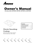
Check door type. Makeanoteofwhetheritisasectionalora
one-piece door for reference later (Figure 2).
SECTIONAL
DOOR,TORSION
SPRINGS
SECTIONAL
DOOR, EXTENSION
ONEPIECEDOOR,TRACKLESS
SPRINGS
Header
Area
Tools used in this section:
• 12% Tape Measure
Check following
• Pencil
• Ladder
items before assembling
• Level
Opener:
Center
Figure 1
Check condition of vertical stile in center of door, and its connection to
door's top and bottom beams. (Figure 1)
A
If door frame is nailed together and not a solid connection, door
frame must be braced or reinforced before installing Opener.
B
If door is "lightweight" (made with frame and skin - not solid),
door (including door frame) must be braced or reinforced before
installing Opener.
C
A door opener reinforcement bracket may also be needed to
connect garage door to Opener's Door Bracket. This Opener is
designed for installation on a properly braced sectional door or
solidly braced one-piece door.
D
Contact your Genie Factory Authorized Dealer or dealer of your
garage door for any necessarybracing and a door opener
reinforcement bracket (if needed) before proceeding.
A
Stile
Note Door Type
Measure door height (floor to top of door) using a tape measure.
B
This new Garage Door Opener is designed for doors up to and
including 7' 6" tall. If door height is7' 6" or lesscontinue to Check Step 4.
C
If door height is 8'-0", you need a Rail Extension Kit. (Figure 3).
(SeeAccessoriesOrder Form, Page 16).
D
If the door height is taller than 8'-0",
the opener you purchased is the
wrong version. Contact
Customer Service
Representative
at 1-800-354-3643.
Rail Extension for
8' door
Figure 3
E
If you have a wooden door, measure door's thickness. If your door
is lessthan 2" thick, brace door or use shorter Door Bracket LagScrews
(1/4" x 1-1/4"- not included)
Rail Extension Kit
NOTE
The header is a heavily reinforced section of the wall just
above the top of the garage door opening.
AND BALANCE
A
Raisedoor, check alignment and see if it moves freely (Figure 2).
If door appears out of alignment, binds, or does not move smoothly,
contact a Genie Factory Authorized Dealer or dealer of your garage
door for repairs and adjustments to door mechanism.
B
Raisedoor to 3' - 4' above ground and carefully let go. Door
should stay stationary. Slight movement is acceptable. More than
slight movement means door is out of balance. Contact a Genie
Factory Authorized Dealer or dealer of your garage
door for repairs and adjustments to door mechanism.
A
Find vertical center line of door and header:
•
Close door.
•
Measure door width at top.
•
Mark a point at center of door and on header directly
above door. Draw a center line to connect points.
B
Find Header Bracket mounting height (Figure 4): (Do not attach
Header Bracket).
•
•
....::::-::::::
KEEP FEET CLEAR OF DOOR
One-Piece
Door
Figure 2 Checking door balance
Raisedoor, watching top edge of door and stop door
when its edge reachesits highest point.
Measure distance ("H") from top edge of door to floor.
-
For sectional doors, add 2-1/2" to "H". Mark a point
on center line. Bottom of Header Bracket will be
installed here.
-
For one-piece doors, add 6" to "H". Mark this point on
center line. Bottom of Header Bracket will be
installed here.
SECTIONAL DOOR
ONE-PIECE DOOR
H÷2_J=2_
......
WARNING:
H
If your door sticks, binds, or is out of balance, have it adjusted
by a Genie Factory Authorized Dealer. Door springs, cables,
pulleys, brackets and associated hardware are under extreme
tension and can cause serious injury or death.
4
Figure 4
Find Highest Point of Travel
ForHelp, call 1-800-3S-GENIEor visit www.geniecompany.com
Perforated
NOTE
•
•
Straps
FINISHEDCEILINGS
Locateceilingjoistsor trussesusing
a stud finderor similardevice.
For all types and styles of doors:
- If the ceiling in your garage is so low that there is
not at least a 3" space above the Header Bracket
mountingpoint,
contact a Genie Factory
AuthorizedDealer.
If a door spring is in the way, place the Header Bracket
above the spring. Do Not move the door spring.
Attach angle iron(not included)
to joists or trusses through finish
material using LagScrews.
WARNING:
Door springs are under extremely high tension and
Figure 6B Mounting methods for open beam or finished ceilings
shou d be hand ed ONLYby a trained professiona.
C
Check wall for a stud or a solid header at your mark: (If checking a
finished wall, a stud finder may be helpful).
•
If location is above Header,a 2"x 6" board must be
screwed to studs beside your mark with at least two Lag
Screwsand Flat Washers(not provided).
•
Transfer your markto new mounting board.
POWERSOURCE
A
Check that there is a 15 Amp 120 Volt grounded electrical
outlet or grounded permanent wiring box (per building code)
within 3' of Opener Power Head (Figure S).
•
If not, an outlet or wiring box must be installed. Contact
a licensed electrician for installation.
If building codes require permanent wiring, Power Head
must be partially disassembled to install appropriate
wiring in place of Power Cord. (SeeAssembly and
Installation Poster.)
Check ceiling or space above where Opener Power Head will be
mounted (Figure 5): There must be a 120Volt grounded outlet or
wiring box within 3 feet of Power Head.
NOTE
Permanent wiring must be installed by a Licensed
Electrician. Not all Genie Factory Authorized Dealers are
Licensed Electrician's. Contact someone who is a Licensed
Electrician.
Grounded
outlet
WARNING:
Do not use and extension cordi Extension cords Can cause
dangerous overheating COnditions:
Do NOt Use p0rtable generat0rs: This pr0duct is designed
to operate on standard house current;
DoNot
1
(8' door)
use alternate power supplies.
Door Center Line
Figure S Check Power Head location
A
The measurements above are taken from the garage door
centerline toward the rear of the garage.
B
Find location of ceiling joist or truss above where Opener Power
Head will be and estimate type and quantity of materials needed for
your installation (Figure 6A & B).
MOUNTING EXAMPLES
Standard
Straps
Extra wood required
Perforated Angle
Iron
_
MOU
lJ..........
n .......LOCATIO
BRACKET
, ......NNTING
Check for wood garage frame, jamb, or masonry at mounting
location (6" above floor) with attachment tabs facing away
from garage door (Figure 7).
A
If you cannot mount Safe-T-Beam ® Mounting Bracket to
wood frame:
.
Concrete screws and concrete anchors (not included)
must be used to mount Brackets on masonry with
attachment tabs facing away from garage door.
Safe-T-Beam®Mounting Bracket Extensions may be used
(not included - available at Dealer or use order form pg. 14.
I
_i_ / ...........
:
Topof
Bracket
Mounting Bracket@/_
6"
above
Figure 7 Mounting
I
floor
Safe-T-Bea
_ ......
Components
Safe-T-Beam ®
Figure 6A
OPENCEILINGSStraps and angle iron may attach directly to joists
or trusses.
For Help, call 1=800=35=GENIEor visit www.geniecompany.com
/
_i
_rr
5
A
B
IMPORTANT
SAFETY INSTRUCTIONS
!LWARNING:
Tools(FigureS):
Additional tools to make installation easier:
•
Slotted and phillips screw-driver bits
•
Stud finder
•
TO REDUCE THE RISK OF
SEVERE iNJURY OR DEATH
Sheet-metal cutting snips
Check that the garage door locks, rope, and T-Handles are
removed from the garage door before starting the installation.
A
If your garage does not have a separate entry door, it is
highly recommended to install a Genie Emergency Release Kit
(GER-2). Emergency Release Kit lets you open the garage door
from outside if there is a power failure. (Please see Accessories
Order Form on page 14.)
Before going further,
1
READANDFOLLOWALLINSTRUCTIONS.
2
Neverlet childrenoperateor playwith the DoorControls. Keep
the RemoteControl awayfrom Children.
3
Alwayskeepthe moving door in sight and awayfrom peopleand
objectsuntil the door iscompletely closed.
NOONESHOULDCROSS
THEPATHOFA MOVINGDOOR.
4
NEVER
GO UNDERA STOPPED,
PARTIALLY
OPENDOOR.
5
TestOpener monthly. The,door MUSTreverseon contact with
a 1-1/2 highobject (ora 2 x4 board laid flat) atthe centerofthe
doorway on the floor. After adjusting eitherthe Forceor the Limit
of travel,retestthe DoorOpener Failureto adjustthe Opener
properly maycausesevereinjury or death.
Whenpossibleusethe EmergencyReleaseon y when the door
isclosed. Usecaution when usingthis Releasewith door open.
Weakor brokenspringsarecapableof increasingthe rateof door
closureand increasingthe riskof severeinjury or death,
KEEPGARAGE
DOORSPROPERLY
BALANCED.SeeOwner's
Manual. An improperly balanceddoor increasesthe riskof severe
injury or death. Havea GenieFactoryAuthorized Dealermake
repairsto cables,springassemblies,and other hardware,
get any items and tools if needed
for your installation
Garage door frame reinforcement brackets, screws, bracing
or reinforcement kits (dealer)
6
Lag Screws(1-1/4") for a wood door lessthan 2" thick (store)
Electrical outlet and/or wiring (supplied by a licensed electrician)
Sufficient angle iron or strapping for hanging Power Head (store)
60 Watt light bulbs (Rough service bulbs recommended)(store)
GER-2Emergency ReleaseKit for entry during power failure (store)
7
8 SAVETHESEINSTRUCTIONS.
Wood for header, ceiling, and/or door braces (store)
Masonry fasteners for Safe-T-Beam® Bracket installation (store)
Safe-T-Beam® Bracket Extensions (dealer)
NOTES, REMINDERS
Masonry drill bit (store)
Extension Kit (for 8' Garage Doors)(dealer)
Go to Assembly and Installation
Installation
Instructions.
1t16"
Drill Bit
Poster for full
5/32"
Drill
Tape Measure'_
Bit
Wire
Stripper
Phillips Screwdriver
Flat Blade Screwdriver
Adjustable Wrench
Safety Glasses
CF i_ ::: :: ....................
Pencil
Hammer
1/4" 5/I6"
Hack Saw
Carpenter's
Figure
6
3/8" 7/16"
Sockets
1/2" 9/16"
AWARNING
Wrench
use the Wall Console induded_ith opener:Any, other wall
console can cause the Opener to operate unexPectedly and the
light to stop working.
Level
8 Recommended
Tools
For Help, call 1-800-35-GENIE or visit www.geniecompany.com
1
_DJUSTMENTS
SET LIMIT
SWITCHES AND
FORCECONTROLS
Coarse Setting
A
of Limit Switches
Setting Close Limit Switch
.
Check that Carriage Assembly is disengaged.
.
With garage door fully closed, slide Close Limit Switch
until it is aligned with the center of the
Carriage Assembly.
.
Tighten Set Screw. Do Not over-tighten.
B
The garage d0oi Opensrapidly; and can cause Sei Ous
injury Ordeath:
Keepthe path clear:
Position the ladder to the side Ofthe Power Head so it
is
€ earof al! mo_ing parts of the Opener and the door
i; Set the door opener to usethe minimum force needed
to open the door:
IB
•
Setting Open Limit Switch
.
Manually open garage door to full open position.
.
Slide Open Limit Switch until it is aligned with the center
of the Carriage Assembly.
.
Tighten Set Screw. Do not over-tighten.
.
Re-engage Carriage Assembly.
Setting Force Controls
Limit Switches
and Final Adjustment
OPEN ADJUSTMENT
•
•
of
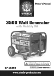
On front panel of Power Head find adjusting
screw marked "OPEN" (Figure 9).
Gently turn screw counterclockwise until it stops.
Very little force is required to turn
adjusting screw.
Press Wall Console to open garage door.
Observe if door stops at "OPEN" limit switch.
If door is fully open--adjustment
is finished.
If door stops but is not fully open,
a. Measure distance between bottom of
b.
i,
:
;
'
The garage door opens rapidlyi and Cancause serious
injury or deathl
Keep the path Clear:
Position the ladde[ to the Side of the Power Head Soit iS
Clear ofall moving parts ofthe Opener and the door,
Set the dooi Opener to use the minimum force needed
to open the door.
A
CLOSE ADJUSTMENT
On front panel of Power Head find adjusting screw
marked "CLOSE" (Figure 9).
•
Gently turn screw counterclockwise until it stops.
Very little force is required to turn adjusting screw.
•
Press Wall Console to close garage door.
Observe if door stops at "CLOSE" limit switch.
If door is fully closed--adjustment
is finished.
Go to "OPEN" Adjustment.
If door stops but is not fully closed,
a. Measure distance between bottom of door
and floor.
b. Move "CLOSE" Limit Switch that same distance
toward door.
o
-
-
If door stops and/or reverses before reaching the
"CLOSE" Limit Switch
a. Slightly increase CLOSE Force setting (clockwise).
If door reverses after contacting floor, move Limit
Switch toward Power Head.
If door fails to move, check Safe-T-Beam ® System. See
Troubleshooting Section, pages 10 and 11.
NOTE
•
•
•
•
Little effort isrequiredto turn the ForceAdjusting Knobs.
If the door stops moving while opening or closing, adjust the
Open Force or Close Force Controls slightly clockwise (to
slightly increasethe force) and retry the step.
The Open Force and Close Force Controls are to be set to the
minimum force necessaryto ensure the door smoothly opens
and closescompletely.
Ensurethe CarriageAssembly is engaged and is between the
two Limit Switches before operating the Opener.
For Help, call 1-800-35=GENIE or visit www.geniecompany.com
-
door and top of door opening.
Move"OPEN" Limit Switch that same
distance toward Power Head.
If door stops before reaching the "OPEN"
Limit Switch
a.
C
Slightly increase OPEN Force
setting (clockwise).
If door fails to move, see Troubleshooting
Section, pages 10 & 11.
Run Door Opener
•
Cycle opener a few times to double check
settings. Repeat adjustment steps as necessary.
OPEN
FORCE ...
LOCATED
UNDER
LIGHT
COVER
CLOSE /
FORCE
CLASS 2 SUPPLY
18-30
VOLTS
Figure 9 Making Force Adjustments
(Located Lower Right Corner).
7
A WARNING
SETTING CONTACT
REVERSE
FUNCTION
A moving garage door may causeserious njury or death.
NOTE
Limit Switch and Force Adjustments must be completed before
checking the contact reversefunction.
A
B
Open garage door using Wall Console.
Lay a 2" x 4" board flat in center of doorway
C
Close door using Wall Console.
D Check that door stops and reverses within
contacts board:
•
•
E
(Figure
10).
2 seconds after it
If door does not reverse, decrease Close Force until
door reverses (Figure 9).
If door still does not reverse, move Limit Switch
toward door.
--_ Keeppeople clearof opening while door is moving.
Do not allow children to play with the RemoteControls,
If the SafetyReversedoesnot work properly:
" Closethe door and disconnect the Opener usingthe
EmergencyReleaseCord.
, Do not usethe door Opener,RemoteControls,or
WirelessKeypad.
• Referto the door and door 0 pener Owner'sManuals
beforeattempting any repairs.
Remote Control Operation
A Press Button on Remote Control. Garage door will move.
B Press Button again. Garage door will stop:
Check Safe-T-Beam ® System operation:
•
If beam is blocked, door
will not close.
•
Press Button again.
Figure 10 F
Checking
Contact
Reverse
_J
/J_-_
2" x 4" board
laid flat
NOTE
The door must contact the 2" x 4" board before the
Carriage activates the Close Limit Switch. If not,
readjust the Close Limit Switch.
D There are several additional varieties of remote controls
available from your local dealer, some equipped with
a flashlight.
_b
©
THE
CLOSE
@
REMOTE CONTROL
B
Program
each additional
Remote using step A above.
from
Power Head Memory
A
Press and hold Learn Button on Power Head for 10 seconds
or until Learn Indicator Light goes out. Memory is erased:
•
Program Remotes again as needed.
To Replace
B
Control
Battery
FOR NON-FLASHLIGHTMODELS
•
Pop off the back of the transmitter.
Use coin, pen, screwdriver or any similar device.
Replace old Battery with new coin type battery.
o
Replace back of remote.
FOR FLASHLIGHT MODELS
•
o
8
Remote
Slide open battery cover.
Replace old Battery with new AAA battery.
Replace battery cover.
FORCE
MORE
_-----
©
LEARN
INDICATOR
LIGHT
LEARN
CODE
BUTTON
Figure 12 Learn Code Button and Indicator
(Located Lower Right Corner).
Learn Indicator Light will stay lit.
Press Remote Control Button again. Red Learn Indicator
Light will go out, indicating that memory is stored.
Press again to Activate Unit.
To Erase All Remotes
A
LOCATED
UNDERTHE
LIGHT COVER
To program one Button of a Remote Control (Figure 11):
•
Locate Learn Button and Learn Indicator Light near
Terminal Block on Power Head (Figure 12).
•
Press and release Learn Button. Red Learn Indicator Light
will blink 2 times per second.
•
Press Remote Control Button once within 30 seconds. Red
•
Garage door will reverse.
....@(h
PROGRAMMING
•
stops at the end of the
Figure 1 1
1-Button and 3-Button
Compact Remotes
w/Docking
Station
ACCESSORIES
A
The door automatically
open or close cycle.
Light.
NOTE
e
Each Remote Control must be programmed
separately.
•
The Remote Controls will not close the garage with
malfunctioning Safe-T-Beam® System.
•
Program Remote Controls, while at least 24" from
Antenna Wire.
•
If the red Learn Indicator Light blinks rapidly,
programming stopped. Restart programming.
Each Button on a multi-button Remote Control is
for a different Opener. Cannot use more than one
Button for same Opener.
A maximum of seven Remote Controls or Wireless
•
•
Keypads can be stored into the Receiver at one
time. If a Remote Control becomes lost, or if you
want to delete a Remote Control or Wireless
Keypad, see "To EraseAll Receiver Memory."
For Help, call 1-800-3S-GENIE or visit www.geniecompany.com
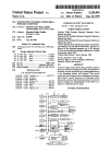
iNSTALLATiON
A
B
OF
LENSAND
BULB
Install a light bulb (1O0Watts or less)(not included) into Light
Socket (Figure 14):
•
Rough service, 130 Volt bulbs are recommended.
Install Lens into slots in Motor Cover.
•
•
Insert Bottom hinges into slots provided in metal front
cover of Power Head.
Flip Lens up and fasten with molded latches on lens.
Transmitter
Transmitters
comply
date
of manufacture
any other
jurisdiction.If
determine
compliance
States
and Canadian
Compliance
Statement
with
all United
States
and Canadian
legal
requirements
as of the
No warranty
is made
that
they
comply
with
all legal
requirements
of
transmitters
are to be used
in another
country,
the importer
must
with
any local laws
and
regulations
which
may
differ
from
United
requirements
prior
to use.
Los transmisores
cumplen
con todas
las reglamentaciones
del Canad&,
en [a fecha
de fabricaci6n.
Ninguna
garantfa
reglamentaciones
legales
de ninguna
otra
jurisdicci6n.
en otro
pals, el importador
debe
determinar
si cumplen
locales
que
puedan
ser diferentes
a las reglamentaciones
Canad&
antes
de usar
los mismos.
[egales
de los Estados
Unidos
y
se da que cumplan
con todas
as
Si los transmisores
se van a utilizar
con
las reglamentaciones
y [eyes
de los Estados
Unidos
y del
Les emetteurs
sont
conformes
_ la reglementation
am_ricaine
et canadienne
_ compter
de leur
date
de fabrication.
Aucune
garantie
n'est
stipul6e
indiquant
qu'ils
sont
conformes
routes
[es prescriptions
juridiques
d'autres
autorit_s.
Si les _metteurs
sont
utilis_s
dans
d'autres
pays,
i[ incombe
a I'importateur
d'en
d_terminer
leur conformit_
aux lois et
regles
locales
pouvant
diff_rer
de celes
des Etats-Unis
et du Canada
avant
toute
utilisation
desdits
_metteur£
Sendeger_ite
Zeitpunkt
gesetzlichen
eingesetzt
Sendeger_te
Bestimmungen
nlF+-t iOl
entsprechen
allen
gesetzlichen
Bestimmungen
in den
USA und
Kanada
zum
Herstellung,Wir
Obernehmen
keine
Gew_ihrleistung
for die Einhaltung
aller
Bestimmungen
in anderen
Lindem.
Sollen
Sendegerite
in anderen
L_ndem
werden,
so muss
der
Importeur
vor dem
Gebrauch
sicherstellen,
dass
die
auch
solchen
Iokalen
Bestimmungen
entsprechen,
wekhe
yon
den
der USA und
Kanadas
abweichen.
der
71El
F&_,_I
Ef-_--_ xlgqlAt
_l-@_Cl_____
+,"-f&_-I
:::z _Cl c"
_-,'q:>- _-_°_;q_i,q_SFTlO_l
I _'_f
__allOtl
[qe-l-oi:
o_,,ti
_;q°l
o:i
_lq_t
_
_HI-F.F_P--IS_
z_oHof
IMPORTANT
SAFETY
INSTRUCTIONS
WARNING-TO REDUCE THE RISK OF
SEVERE INJURY OR DEATH
Figure 14 Install Lens and Light bulb
NOTES
1
READAND FOLLOWALLINSTRUCTIONS.
2
Never let children operate or play w th the Doo_
Controls. Keep the Remote Control away from children.
3
Always keep the moving door in sight and away from
people and objects until the door iscompletely closed.
NO ONE SHOULD CROSSTHE PATH OF THE
MOVING DOOR.
4
NEVERGO UNDER A STOPPED,PARTIALLY
OPEN DOOR.
5
Test Opener monthly,. The door MUST reverse on
contact with a 1-1/2 high object (ora 2 x 4 board
laid flat) at the center of the doorway on the floor. After
adjusting either the Force or the Limit of travel, retest
the Door Opener. Failureto adjust the Opener properly
may cause severe injury or death,
8
When possibleusethe EmergencyReleaseonly when
the door isc osed. Use caution when using this Reease
with the dooropen. Weakor brokenspringsare capable
of increasingthe rateof door closureand increasingthe
riskof severeinjury or death.
7
KEEPGARAGEDOORS PROPERLYBALANCED. See
Owner's Manual. An improperly balanced door increases
the risk of severe injuryor death. Have a Genie Factory
Authorized Dealer make repairs to cables,spring
assemblies,and other hardware.
8 SAVETHESEINSTRUCTIONS.
For Help, call 1-800-3S-GENIE or visit www.genie¢ompany.com
SCHEDULED
MAINTENANCE
Reattach Carriage Assembly to Rail Assembly:
a. Pull the Emergency Release Knobtoward
Power Head.
b. Close door.
A Monthly:
o
Door springs and door hardware:
- Oil door roller, bearings, and hinges using silicone
lubricant or light oil.
Contact Reverse Test,
Perform Adjustment Step 2 on page 8.
A WARNIN
J
--Do not operate door a uto atiCally 0r man_al/y if Springs
are broken, Contact a Genie Fact0ry Authorized Dealer for
service or call Customer Service at 1,800,35'GENIE.
!
•
Balance Door.
-
Close door.
ReleaseCarriage Assembly from Rail Assembly by pulling
down on Emergency Release Knob.
Raisedoor manually 3'- 4' and verify that door stays at
that position. See Check Step 2 on page 4.
NOTE
When the door is 3'- 4' above the ground, the door
should stay open. Slight movement isacceptable. If
the door moves too much, contact a Genie Factory
Authorized Dealer for service or call Customer Service at
1=800=35=GENIE.
TROUBLESHOOTING
AWARNING
If the door fails to reverse on contact with the board,
adjust the Close Force Control as specified in Set Limit
Switches and Force Controls on page 9. If the Opener still
fails, contact a Genie Factory Authorized Dealer for service
or call Customer Service at 1-800-35-GENIE.
FCC AND IC CERTIFIED
All devices comply with Part 15 of the FCCRules.
Operation is subject to the following two conditions: (1)
this device may not cause harmful interference, and (2)
this device must accept any interference received, including interference that may cause undesired operation.
B As Needed:
•
Replace Light Bulb
GUIDE
Safe=T=Beam ® System Self=Diagnostic
Troubleshooting
Possible Problem
ON
Normal operation
None required
OFF
OFF
o Power Head not powered
o Wiring from Power Head bad
. Check breakers, fuses, plugs
. Check wiring for obvious shorts
OFF
ON
o Wiring to Source missing or bad
o Power has been interrupted
. Check wiring
. Remove power and reapply
2 BLINKS, Pause
(Repeat)
ON
o Beam not aligned
o Beam obstructed
o Sensor defective
. Check Source, Sensor alignment
. Check for obstruction
. Contact Customer Service
OFF
o Wire to Sensor missing or bad
o Sensor defective
o Check wiring
o Contact Customer Service
o Sensor receiving
o Determine
2 BLINKS, Pause
(Repeat)
Sensor (Green LED)
3 BLINKS, Pause
(Repeat)
interference
4 BLINKS, Pause
(Repeat)
ON
source of interference
o Check for sunlight or another
opener on nearby door
. Contact Customer Service
ON
10
Solution
Source (Red LED)
ON
. Source not sending pulses
. Source defective
o Contact Customer
. Contact Customer
Service
Service
For Help, call 1=800-35-GENIE or visit www.geniecompany.com
General
Problem
Openerdoesnot run
from WallControl
Troubleshooting
What To Do
1. Check Lock switch on Wall Control Installation Poster.
2. Check Power Source:
•
•
For Grounded Plug Connection.
- Plug a lamp into the electrical outlet used for the door opener.
a. If lamp lights, power source is good.
b. If lamp does not light, check fuse or circuit breaker.
For Permanent Wiring Connection.
- Check fuse or circuit breaker.
3. Check connections (see Wall Console Installation on Installation Poster):
• At Power Head Terminals and Wall Control.
Door Opener starts
for no apparent reason
1. Check Wires to ensure that they are not cut (Staples can cut insulation and short Wires)
Replace any shorting Staples and shorted Wires.
2. Was Remote Control lost or stolen? If so, erase all Remote Control codes from Receiver's memory
and reprogram for remaining remote controls. (See EraseAll Receiver Memory on page 8).
3. Ensure that no Buttons are stuck "pushed-in" on Wall Console or any Remote Controls.
Door starts down, then
stops before it is
completely closed
1. Check Close Limit Switch setting (page 7 and poster). Adjust as needed.
2. Check Force Setting (pages 7).Adjust as needed.
3. Check for shorted wires.
Door starts down, then
stops and goes back up
1.
2.
3.
4.
5.
6.
Door will only run closed
1.
2.
3.
4.
Doorwill onlyrun open
1. CheckSafe-T-Beam®Systemas detailed in the Safe-T-Beam® System Self-diagnosticTroubleshooting Chart
(page 10).
2. CheckCloseLimit Switch for a short circuitand for proper wiring.
3. CheckCloseForceadjustment (seeSet Limit Switches and Force Controlson pages 7). Adjust asneeded.
Lights will not turn off
1. Disconnect Wires connectingPushbutton to Power Head (seePushbutton Installation on poster).
Checktheir conditionand either replaceor reconnect.
2. Until a replacement Wall Consolecan be obtained, disconnect Wall Consoleand use only Remote Controls
or Wireless Keypad to operate Opener.
3. Check for non-compatible wall control.
Door starts up,
but stops beforeit is
completely open
1. Check (ensure) that garage door and Opener are in good repair, properly lubricated, and properly
balanced as detailed in Maintenance Section.
Ifa new installation, check Door Arm position.
Check operation of Contact Reversefunction.
Check Safe-T-Beam®Systemfor beam obstruction or misalignment of Lenses.
Check Safe-T-Beam®System diagnostic code.
Check CloseForceadjustment (seeSet Limit Switches and Force Controls on pages 7). Adjust as needed.
Check garage door for binding.
Check Open Limit Switch for a short circuit and for proper wiring.
Check Open Force adjustment (seeSet Limit Switches and ForceControls on pages 7). Adjust as needed.
Check condition of garage door and door spring(s).
WARNING: If you suspecta problem with the garage door hardware or springs, contact a Genie
Factory Authorized Dealer for service,or contact Customer Serviceat 1-800-35-GENIE.
5. CheckPosition of Lock Switch on Console.
2. WARNING: If you suspecta problem with the garage door hardware or springs, contact a Genie Factory
Authorized Dealer for service, or contact Customer Serviceat 1-800-3S-GENIE.
3. CheckOpen Limit Switch for a short circuitand for proper wiring.
4. CheckOpen Forceadjustment (seeSet Limit Switches and ForceControlson pages 7). Adjust as needed.
Operator runs, but door
does not move
1. EnsureCarriageAssembly is engaged to CarriageSlide (seeInstallCarriage
Assemblyonto Railson InstallationPoster).
2. CheckForceadjustment (seeSet Limit Switches and Force Controlson pages 9 and 10). Adjust as needed.
Wall ConsoleVacation
Lock function does
not work
1. EnsureCarriageAssembly is in contactwith CloseLimit Switch.
2. Checkwhen door is fully closed,that Carriageactivates CloseLimit Switch. If not, adjust position of Close
Limit Switch (Seepages 7).
Noisy Operation
1. Be sure all fastenersare tight.
2. Check (ensure) that garage door and Opener are in good repair, properly lubricated, and properly
balanced as described in Maintenance Section (page 10).
For Help, call 1-800-35-GENIE or visit www.geniecompany.com
11
PARTS
iDENTIFICATION
Power Head Parts List
[1]
Power Head Assembly
Number
_.auded
.1 Item Part
PowerName
Head Assembly
1
* 1A
* 1B
* 1D
Cover (by Series Model)
Front Panel Assembly
Motor Parts
1
1
1
* 1E
Circuit
1
* 1F
1G
Capacitor (By Series/Model)
Opto Wheel (not shown)
1
1
* 1H
* 1J
1K
Carriage Slide
Chain
Circuit Board Bracket
1
1
1
* 1L
Drive
1
* 1M
* 1N
Terminal Strip
No. 8-32 x 3/4" Hex Head Screw
w/int. Lockwasher
1
1P
* 1Q
1X
4
Shock Absorption
Stop
Motor Mount Bracket (not shown',
Chassis
1/4-20 Shoulder Bolt
1
1
1
1
5
39
1/4" Flange Nut
Coupler
1
1
41
No. 8-32 x 3/8" Phillips
Hex Head Screw
1
42
No. 8-32 x 3/8" Phillips
Pan Head Screw
1
48
Mountinq
2
49
Light Lens
Board Assembhz
Module
1
Straps
1
* Pre-assembled
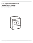
WIRING
DIAGFIAM
[
A
Shut 0ff Cower
[Components
inside
bef0re
Cover
0penilg
May Cause
the cdver:
Electric Shock J
,
,
M°L°R.
I
I
THERMAL
] PROTECTOR
BLACK
I
_,_
'
_
[
_
_i:Y
,,,,,(::_
"_
I
i
_'_/
I
i
RED
J
ORANGE
[
[
_
MOTOR
I
;RED
j
YELLOW
POWER HEAD TERMINALS
YELLOW',
i
WALLCONTROL
YELLOW
POWER CORD
2
z
/_7 _
®®®o6®®®@®®®
OPENLIMIT
SEQUENCER HOUSING
OPIN
COMMON
IIM]
SWITCH
BLUE
WHITE
LIGHT
CLOSELIMIT
[_.
12
(JO'l
LMIT SWTCH
For Help, call 1-800-35-GENIE or visit www.geniecompany.com
PARTS i DENTIFICATION
[2]
Rail Assembly
\
Parts List
item
1
2
4
8
9
10
11
12
13
14
15
16
17
18
20
22
23
24
25
26
27
28
29
30
Part Name
Parts List
item
m
1
Power Head Assembly (main box)
RailAssembly (1-piece)
I
RailAssembly_3:piece)(main box)
I
5 First Rail Section (separate box)
I
6 Middle Rail Section (separate box)
I
7 End Rail section (separate box)
4
RailClamps (blue bag)
12
1/4"-20x 5/8" HexHead Bolt (blue bag)
12
1/4"-20" Hex Flange Nut (blue bag)
I
Carriage Assembly (main bag)
I
RailStrap (blue bag)
I
Limit Switch (white wire)(blue bag)
I
Limit Switch (brown wire)(blue bag)
I
ReleaseCord (green bag)
I
ReleaseKnob (green bag)
I
Emergency ReleaseTag (green bag)
I
Header Bracket orange bag)
I
Door Bracket (orange bag)
8
1/4" x 2" Lag Screw (orange bag)
I
Straight Door Arm (main box)
2
Clevis Pin (yellow bag)
2
Cotter Pin (yellow bag)
Curved Door Arm (main box)
I
2
3/8"-16 x 7/8" H. H. Bolt (yellow bag)
2
3/8"-16 Hex Nan e Nut ( ellow ba )
I
Wire (main box)
Insulated Staples(red bag)
variesby
Part Name
m
31
Wall Button (red bag)
variesby
model
32
Wall Console (main box)
varies by
model
33
#6 x 1-1/4" pan head phillips screw
34
35
36
37
38
Entrapment Warning Label (manual)
Safe-T-Beam®Sensor (main box)
Safe-T-Beam®Source (main box)
Safe-T-BeaM®Mountinq Brackets
Remote Controls (main box)
varies by
model
1
1
1
2
39
#8-32 x 1" Machine Screw (green bag)
40
41
46
1
Safety and Maintenance Guide (manual)
Wire Clips
varies by
model
1/4"-20 x 3/4" Self-drilling Screws
3
(orange bag)
#10-16 x 1-1/4" Phillips Hex Head Screw
4
(yellow bag)
5/16"-18 x 3/4"Hex Head Bolt
47
48
(orange bag)
5/16"-18 Hex Flange Nut (orange bag)
Mounting Straps (main box)
42
44
varies by
model
2
3
4
2
model
For Help, call 1-800-3S-GENIE or visit www.geniecompany.com
13
GarageDoorOpener Accessories
Order Form
Formulairede commandodesaccessoirespourouvre-porte de garage
How
For additional accessories not shown, visit our website at www.geniecompany.com
pour les accessoires suppl4mentaires pas montr4, visiter notr_ site web _ www.geniecompany.com
many?
Comment
beaucoup?
(GKT-1-390) 1-ButtonCompact
Remote-Allowsremoteoperationofgaragedoor.
1-Boutenner
T_l_cornrnaade
cornpacte
- Permettre
operation
_loign"deportedegarage.
P/N 36248R
Ordering
536.50
(GiFT-I-390) 1-ButtonFlashlightTransmitter
- Remote
Controller
withaFlashlight.
1-houtenner
['_rnetteurde[arnpedepoche- Lecontr61eur
_loign_avecdelampedepoche.
P/N 35657R
545.00
{GICT-3-390)3-Bu_enCornpactBernete-AIIowsremoteoperationof3garagedoors.
Please add
3=boutennerlaT_l_cornrnandecornpacte- Permettreoperation _loign'
trois portes de ara e.
P/N 36223R
550.00
(GWC-2W) Deluxe Wall Console - OperatesGarageDoor.Independent light control. Securityvacation lock.
Connecticut,
Maryland,
Massachusetts,
Tennessee,
TOTAL
535.00
Florida,
Michigan,
Virginia,
in one of the
Georgia,
New
states
listed.
Illinois,
Indiana,
Jersey,
New
York,
Wisconsin
ORDER
SHIPPING
(GWKPD)DualFrequency
WirelessKeypad-Operates
Intellicode'
Garage
DoorOpeners
withoutRemote
Control
or key.
Syst_rne
d'ouvre-pertedegarage_ claviersansfil- Actionnelesouvre-porte
degarageavec
Intellicode'
sanst_l_commande
nicl&
P/N 35691 R
local sales tax if you reside
Californla,
Ohio,
LaConsole dseluxe de Mur- Actionne la porte degarage.Commanded'_clairageind_pendante.
Interrupteurde verrouillagede s_curit&
P/N 35661R
Instructions
No C.O.D. shipments. Please include check or money order,
made payable to The Genie Company. Do not send cash.
Allow 3-4 weeks for delivery.
1-800-354-3643. Please have part number and credit
card ready. Mail Order Form to: Genie Company, 22790
Lake Park Blvd, Alliance, Ohio 44601. We accept Visa or
Mastercard on phone orders only.
$
& HANDLING
$
STATE SALESTAX
$
GRAND
$
TOTAL
6.00
550.00
(GLU-3)3/4 oz. ScrewDrive Lubricant - Ensuresproper equipment wearprotection.
Laonza3/4 Lubricantde la vis - Garantircomponantexactparsyst_med_fenseversuser.
P/N 35218AS
(Gw-2)
55.00
Universal Wall Button- Providesadditional convenientinsideoperation of door.
Instructions
Bouten mural universal - Actionne I'ouvre-portede I'int_rieurdu garage.
P/N 35693R
53.75
P/N 35677R
54.00
(6PS-5) Perfect Step-
Ensuresperfect parking.
Butoir Perfect Stop- Permetde stationner_ laperfection dans legarage.
(GABXS)BeltDriveExtensionKit-AnExtension
thatincreases
the travelofa beltdrivenOpenerto
accommodate
aneightfootdoor.
N_cessaire
de prolongernent
du coulisseau-Rallonge
deprolongeant
lacourse
derouvre-porte
BeltDrivepouruneportede2,4m(8pi)dehauteur.
P/N 35663R
Veuillez
532.00
les taxes de vente
locales si vous r4sidez
dans I'un des
¢i-dessous.
California,
Connecticut,
Maryland,
Massachusetts,
Tennessee,
Virginia,
Florida,
Georgia,
Michigan,
New
Illinois,
Indiana,
Jersey,
New
York,
Wisconsin
Chain Drive Extension Kit- An Extensionthat increasesthe travelof a ChainDrivenOpenerto
accommodateaneight foot door.
COMMANDETOTALE
$
N@cessairede prolongernent du coulisseau - Rallongedeprolongeantlacoursede rouvre-porte
du conduit dechain pour une portede2,4 m (8 pi) dehauteur.
MANUTENTIONETEXPEDITION
$
TAXEDEVENTE
$
TOTALGLOBAL
$
P/N 35679R
(GSX-8)
indiquer
_tats r4pertori4s
Ohio,
(LCGX-8)
Commandant
Pasd'exp_dition centre remboursement.Veuillezinclure un cheque
ou un mandat bancaire,le payablefait a The Genie Company.
N'envoyez pasd'argent comptant. Accordezde 3 _ 4 semaines
pour la livraison.1-800-354-3643.Ayez sousla main le num6ro de la
piece et celui de lacarte de credit. Mettre _ la paste learrngement
_:GenieCompany,22790 LakePark Bivd, Alliance, Ohio 44601.
Nousacceptons lescommandespar t_l@hone avec paiementpar
carte de creditVisaou Mastercard.
532.00
6.00
ScrewDriven Extension Kit - An Extensionto increasetravel of a screwdriven Operatorto accommodate
an eight foot door.
coursedeI'ouvre-portepour
une porte
de 2,4
m (8 pi) de
hauteur.(GIRU-lT)
N_cessairede taffonge du Screw
DriveRallongede
prolongeant
la
_-e_
P/N 35678R
532.00
(60WATT)Enhanced/Rough
Service
LightBulb-Ensures
properequipment
compatability.
Eclairagede 50 WATT- Garantircomponantexactpar syst_me.
P/N 26210A.S
52.73
SHIP ORDER TO:
(GER-2) Emergency
Release Kit - Provides access to garage from outside in the event of
an electrical power failure.
N6cessaires de D4clenchement
EXPEDIER MARCHANDISE POUR:
NAME / NOV
de secours - Le n_cessaire de d_clenchement
de secours est con_upour vous permettre d'acc4der & votre garage depuis
I'ext_rieur en cas de panne de courant et Iorsqu'il.
P/N 35675R
STB
ADDRESS / ADRESSE
520.00
Adapter Brackets (2) - Used in conjunction with standard STBBrackets. They
provide additional clearance and mounting options.
STATE / ETAT
ZIP / CODE POSTAL
Crochets d'adaptateur
(2) - Utilis_ conjointement avec STBstandard reenter
les crochets, ils fournissent le d_gagement suppl_mentaire avec monter d'options.
P/N 34439R.S
14
CITY / VILLE
54.37
(Pricessubject to change without notice)
(Lesprix assujettissent pour changer sansla notification)
For Help, call 1=800=35=GENIEor visit www.geniecompany.com