1
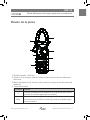
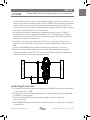
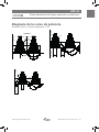
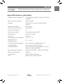
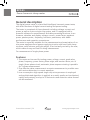
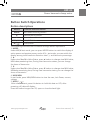
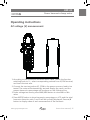
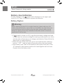
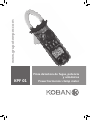
www.grupotemper.com
KPF 01
Pinza detectora de fugas, potencia
y armónicos
Power harmonioc clamp meter
KPF-01
Pinza detectora de fugas, potencia y armónicos
Índice
Instrucciones de seguridad
3
Símbolos de seguridad
3
Descripción general
4
Características
4
Diseño de la pinza
5
Funciones del selector rotatorio
6
Función de los botones
7
Pantalla LCD
8
Instrucciones de funcionamiento
9
Medición de tensión CA
9
Medición de corriente CA
10
Prueba de circuitos monofásicos
10
cosΦ/ángulo de fase
11
Circuito monofásico de tres líneas
12
Tensión y corriente de entrada
12
Retroiluminación
12
Auto apagado
12
Diagrama de la curva de potencia
13
Indicador de batería baja
14
Especificaciones generales
15
Especificaciones técnicas
16
Accesorios
17
Manual de instrucciones | 2
www.grupotemper.com
KPF-01
Pinza detectora de fugas, potencia y armónicos
Instrucciones de seguridad
Lea detenidamente este manual antes de comenzar a utilizar la pinza, y
ponga especial atención a las precauciones.
1.Tenga especial cuidado cunado mida tensiones por encima de 30V CA.
Mantenga los dedos por detars de las barreras de las puntas de prueba.
2.No mida tensiones por encima de los límites indicados para el
instrumento.
3.Compryuebe el estado de la pinza y las puntas de prueba anstes de su
uso. No realice mediciones si las puntas de prueba están están dañadas, la
carcasa de la pinza presenta roturas o la pantalla LCD no muestra lecturas.
4.El cumplimiento de las medidas de seguridad solo puede ser garantizado
si se utilizan las puntas de prueba suministradas. En caso de estar dañadas
cámbielas por otras iguales o con las mismas especificaciones eléctricas
5.No exponga la pinza a la luz directa, a altas temperaturas o a la humedad.
Este instrumento está diseñado y fabricado de acuerdo a la norma
IEC61010-1, y en concordancia con la norma de seguridad, IEC1010-2-032,
sigue estrictamente el estandar de seguridad de doble aislamiento AC 600 V
CAT III.
Símbolos de seguridad
Precaución, riesgo alto. Siga las instrucciones de este
manual
Peligro de alto voltaje
Toma de tierra
Doble aislamiento (Protección clase Ⅱ)
Indicador de batería baja
www.grupotemper.com
Manual de instrucciones | 3
KPF-01
Pinza detectora de fugas, potencia y armónicos
Descripción general
Esta pinza es un instrumento manual para la medición de armónicos, puede
llevar a cabo pruebas de corriente y potencia.
El medidor se compone de tres canales, tensión, corriente y potencia,
así como un sistema de microchip equipado con un potente software
de medición y procesamiento de datos; puede medir y calcular tensión,
corriente factor de potencia, potencia aparente potencia pasiva, frecuencia y
parámetros de armónicos con un rendimiento estable.
Está especialmente indicado para la medición y examen de equipos eléctricos
y circuitos de potencia en campo; su estructura de pinza, ligera y pequeña
puede ser fácilmente transportada por el usuario.
Diseñada para la medición de fuentes de corriente monofásicas.
Características
1.Este medidor puede ser utilizado para pruebas de potencia, tensión,
corriente, picos, fase, frecuencia, ángulo de fase, etc de circuitos
monofásicos o trifásicos; para mediciones trifásicas es posible realizar la
prueba automática de secuencia de fases.
2.Permite realizar mediciones de valor eficaz verdadero incluso con
distorsiones considerables en la forma de la onda de la corriente.
3.Emplea un microchip de bajo consumo y alta velocidad que emplea
un sofisticado algoritmo, lo que permite obtener resultados rápidos y
precisos y medir hasta 20 valores de armónicos y de distorsión.
Manual de instrucciones | 4
www.grupotemper.com
KPF-01
Pinza detectora de fugas, potencia y armónicos
Diseño de la pinza
1
8
7
2
6
3
5
m
4
1.Tamaño maxilar:Ф26mm
2.Selector de funciones: selector rotatorio para seleccionar las diferentes
funciones
3.Botón de selección de función: botón para el manejo de las funciones de
medición.
4. Toma de entrada
Terminal Función
V
Toma de entrada para la medición de la primera fase; utilice
la punta de prueba roga para la conexión
COM
Toma común: toma de entrada negativa (tierra) para todas
las funciones de medición; utilice la punta de prueba negra
para la conexión.
www.grupotemper.com
Manual de instrucciones | 5
KPF-01
Pinza detectora de fugas, potencia y armónicos
5. Pantalla LCD : 4 dígitos; 7 secciones para mostrar las funciones de
medición, resultados de pruebas y unidades de medida.
6. H/
:botón HOLD: para retener los datos de las lecturas en la pantalla
pulse el botón HOLD, la pantalla mostrará el símbolo HOLD. Púlselo de
nuevo para volver al modo normal.
7. Gatillo: apriete el gatillo para abrir las pinzas y deje de pulsarlo para volver
a cerrarlas.
8. Luz LED
Funciones del selector rotatorio
El selector rotatorio se utiliza para encender el instrumento y para cambiar a
los modos de medición de la tabla siguiente.
Descripción de posiciones del selector
Símbolo
Posición
Función
OFF
Posición de apagado
Apagado
KW
Potencia activa
Para medir la potencia activa, etc
W
Potencia
Para medir la potencia activa, etc
V∽
Prueba de armónicos de
tensión CA
Medición de armónicos en la
tensión, etc
A~
Prueba de armónicos de
corriente CA
Medición de armónicos en la
corriente, etc
mA~
Prueba de armónicos de
corriente CA
Medición de armónicos en la
corriente, etc
Nota:
Cuando el medidor se apague automáticamente, coloque el selector
rotatorio en la posición OFF y no lo encienda hasta que hayan transcurrido 5
segundos.
Manual de instrucciones | 6
www.grupotemper.com
KPF-01
Pinza detectora de fugas, potencia y armónicos
Función de los botones
Descripción de los botones
Botón
Función
MODE
Botón de modo de pruebas
▲
Botón de retroceso
▼
Botón de avance
MIN/MAX
Valor MAX/MIN
H/
Retención de datos y luz (HOLD/LIGHT)
Mediante los botones se pueden realizar las siguientes operaciones:
1. MODE:
En el modo KW/W, pulselo para mostrar la potencia activa o la potencia
pasiva; en el modo A/V~, púlselo para mostrar la distorsión total de
armónicos F, r, y el porcentaje de armónicos.
2. ▲:
En el modo de visualización de valores Max/Min, pulse ▲ para cambiar la
vista entre valor MAX, valor MIN, tiempo de medición; Si está viendo el
estado de los armónicos puede cambia el tiempo de los mismos.
3. ▼:
En el modo de visualización de valores Max/Min, pulse ▲ para cambiar la
vista entre valor MAX, valor MIN, tiempo de medición; Si está viendo el
estado de los armónicos puede cambia el tiempo de los mismos.
4. MAX/MIN:
En el modo de prueba, pulse el botón MAX/MIN para ver los valores
máximos o mínimos de potencia, tensión y corriente.
5. HOLD/
:
Después de realizar una medición pulse este botón para mantener los
datos en la pantalla; si presiona este botón durante más de 1 segundo se
encendará o apagará la luz LED.
www.grupotemper.com
Manual de instrucciones | 7
KPF-01
Pinza detectora de fugas, potencia y armónicos
Pantalla LCD
Símbolo
LAG
SINФ
Hz
MIN
W
VAr
PHASE
%
Descripción
Símbolo
Descripción
Auto apagado
HOLD
Hold
Retardo del angulo de
fase
LEAD
Phase angle lead
Batería baja
o
Phase angle (degree)
Ángulo de fase
(grados)
COSФ
Power factor
CA
PEAK
Peak value
Valor mínimo
MAX
Maximum value
Watios
A
current
Potencia pasiva
VA
Apparent power
Fase
TRMS
TRMS
Porcentaje de
armónicos
V
Voltage
Negative symbol
Frecuencia
%THD
Ratio de distorsión armónica total
H01F
Ratio de distorsión armónica total F (en relación a la onda)
H01r
Ratio de distorsión armónica total r (en relación al valor
efectivo real)
Manual de instrucciones | 8
www.grupotemper.com
KPF-01
Pinza detectora de fugas, potencia y armónicos
Instrucciones de funcionamiento
Medición de tensión CA
AC
V
UL
UL
TL88-1
TL88-1
MASTECH
MASTECH
m
1.De acuerdo con el esquema de conexión superior, coloque el selector
giratorio en la posición V~, conecte las puntas de prueba a las tomas V y
COM.
2.Conecte el extremo de las puntas de prueba V1 y COM a la fuente
de corriente. El medidor mostrará el resultado y la el porcentaje de
armónicos presentes en la siguiente línea.
3.En el modo de prueba de tensión, presione el botón MAX/MIN para
visualizar los valores máximos y mínimos.
4.Pulse el botón MODE para ver el porcentaje de armónicos, la pantalla
mostrará cíclicamente el ratio F y r de distorsión armónica total. Pulse los
botones ▲/▼ para mostrar el valor de cada medición de armónicos.
www.grupotemper.com
Manual de instrucciones | 9
KPF-01
Pinza detectora de fugas, potencia y armónicos
Medición de corriente CA
1
2
3
N
m
1.Coloque el selector giratorio en la posición A~.
2.Presione el gatillo para abrir la pinza y rodee el cable a medir; la pantalla
mostrará el valor medido de la corriente.
3.Pulse el botón MODE para ver el porcentaje de armónicos, la pantalla
mostrará cíclicamente el ratio F y r de distorsión armónica total.
4.Pulse los botones ▲/▼ para mostrar el valor de cada medición de
armónicos.
5.Pulse el botón MAX/MIN para visualizar los valores máximos y mínimos.
Prueba de circuitos monofásicos
1.Sujete la pinza en el cable de prueba de la fuente de alimentación o la
carga. Si necesita medir una fase en concreto o un circuito trifásico, sujete
la pinza en el cable de la misma fase.
2.Coloque el selector giratorio en la posición KW/W, seleccione las tomas
de entrada V1 o COM correspondientes e introduzca el cable a probar.
3.Si la conexión es correcta podrá medir potencia monofásica (potencia
activa, factor de potencia, potencia aparente, potencia pasiva, tensión,
corriente, ángulo de fase, picos de tensión y corriente y frecuencia).
4.El medidor realizará las mediciones de potencia activa automáticamente y
Manual de instrucciones | 10
www.grupotemper.com
KPF-01
Pinza detectora de fugas, potencia y armónicos
el valor de la tensión o la corriente de la carga a prueba se mostrará en la
línea inferior de la pantalla; pulse el botón MODE para mostrar la potencia
pasiva; pulse de nuevo para mostrar la potencia aparente y el factor de
potencia (cos Φ); si el factor de potencia es negativo significa que la carga
tiene las características de un condensador.
5.La escala de medición máxima de la potencia activa es de 120 kW; si
se excede este valor la pantalla mostrará OL. Si la tensión que se está
probando es mayor de 600V o la corriente es mayor de 200A la pantalla
también mostrará el símbolo OL.
6.La tensión mínima de entrada es de 10V y la corriente de 10mA; si la
potencia activa es menor que de estos valores la pantalla mostrará 0.00
kW.
7.Presione MAX/MIN para visualizar los valores máximos y mínimos.
8.El valor de la potencia pasiva no es medido directamente; la ecuación
utilizada es kVAr2=kVA2-kW2; su valor es calculado mediante software en
base a la tensión, corriente y potencia activa.
Load
Power supply side
Black
Red
m
cosΦ/ángulo de fase
1.Coloque el selector giratorio en la posición KW/W y las puntas de prueba
en las tomas V1 y COM.
2.El medidor mostrará automáticamente los valores del factor de potencia,
la tensión y la corriente.
3.Pulse el botón MODE para mostrar el ángulo de fase, factor de
potencia(cos Φ);
4.Pulse MAX/MIN para visualizar los valores máximos y mínimos y el tiempo
de medición.
www.grupotemper.com
Manual de instrucciones | 11
KPF-01
Pinza detectora de fugas, potencia y armónicos
Circuito monofásico de tres líneas
El proceso para medir la potencia y el factor de potencia de este tipo de
circuitos es el mismo que el utilizado para medir circuitos monofásicos de
dos líneas. Conecte el clip negro al cable central y el clip rojo y la pinza a los
cables a probar.
Red
Power supply side
Black
Black
m
Red
m
Tensión y corriente de entrada
Durante la medición de potencia si la tensión de entrada es mayor de 600V
(RMS) o la corriente lo es de 200A (RMS), la pantalla mostrará OL.
Retroiluminación
Pulse el botón
durante más de un segundo para encender la
retroiluminación, esta se apagará automáticamente transcurridos 20
segundos.
Auto apagado
1. Si no utiliza el instrumento durante más de 10 minutos, este se apagará
automáticamente. Cuando el medidor se apague automáticamente,
coloque el selector rotatorio en la posición OFF y no lo encienda hasta
que hayan transcurrido 5 segundos.
2. Mantenga pulsado el botón
al encender el medidor para desactivar
el auto apagado.
Manual de instrucciones | 12
www.grupotemper.com
KPF-01
Pinza detectora de fugas, potencia y armónicos
Diagrama de la curva de potencia
(Potencia activa = potencia aparente × PF)
+V
+I
+P
PF=kW/kVA
2000W
+E
+I
+P
2000W
P
vMAX
PEAK VALUE OF POWER
EMAX=141V
PEAK VALUE
+i
1000W
-E
-I
-P
IMAX
+v
ACTIVE POWER
X
180
O
POWER
90
O
180
IMAX =14A
360
O
PEAK VALUE
+V
+I
+P
O
-E
-I
-P
-i
0-
0-
-V
360
O
P
vMAX
IMAX
500W
ACTIVE POWER
kW=I R
2
45
O
90
180
O
O
225
-E
-I
-P
O
270
O
360
O
045
O
045
O
www.grupotemper.com
Manual de instrucciones | 13
KPF-01
Pinza detectora de fugas, potencia y armónicos
Indicador de batería baja
Si las pilas del medidor están bajas de carga la pantalla mostrará el símbolo
. Cámbielas por una nuevas.
Cambio de las pilas
Precaución
Asegúrese que el instrumento está apagado y las puntas de prueba no
están conectadas a ningún cable antes de abrir la tapa de las pilas para
evitar descargas eléctricas.
Antes de susar el instrumento asegúrese que la tapa de las pilas está
firmemente cerrada.
Use únicamnete pilas del mismo modelo o de iguales especificaciones que
las suministradas.
Cuando la carga de las pilas esté por debajo del nivel mínimo para asegurar
la precisión de las lecturas, aparecerá el símbolo
en la pantalla y deberá
cambiarlas. Siga los siguientes pasos:
1.Gire el selector rotatorio a la posición OFF, desconecte las puntas de
prueba de cualquier circuito y de las tomas del medidor.
2.Abra la tapa de las pilas y cambie las viejas por unas nuevas de 1,5V. No
use pilas nuevas y usadas al mismo tiempo. Vuelva a cerrar la tapa de las
pilas.
Manual de instrucciones | 14
www.grupotemper.com
KPF-01
Pinza detectora de fugas, potencia y armónicos
Especificaciones generales
Clasificación de seguridad:
Cumple IEC/EN 61010-1 1000V CAT II ,600
V CAT III
Máx. tensión de entrada:
600V CA RMS
Pantalla:
Pantalla LCD; Lecturas máximas: 6000
cuentas
Selección de escala:
Automática
Detección de frecuencia:
Automática
Aviso de sobrecarga:
OL
Retención de datos:
La pantalla muestra HOLD
Alimentación:
3 pilas 1.5 V, AAA
Consumo:
250 mW
Temperatura de almacenaje:
-20 °C ~ 70 °C
Temperatura de
funcionamiento:
0 °C ~ 40 °C
Coeficiente de temperatura:
0.05×(precisión especificada) por °C
Compatibilidad
electromagnética:
En un campo de RF de 3V/M,
precisión=precisón especificada, en otros
casos no está especificada.
Altura de funcionamiento:
2000m CAT Ⅲ 600V;3000m CAT Ⅱ600V
Altura de almacenaje:
12000m
Dimensiones:
208mm×78mm×35mm
Peso:
apróx. 350 g (pilas incluidas)
www.grupotemper.com
Manual de instrucciones | 15
KPF-01
Pinza detectora de fugas, potencia y armónicos
Especificaciones técnicas
Precisión: ±(% de lectura + digitos) a 18ºC ~ 28ºC; humedad relativa <80%;
frecuencia de tensión, corriente: 45 Hz ~ 65 Hz. AC Voltage
Escala
Resolución
10V-600V
0.1V
Impedancia de entrada: 10MΩ/10pF.
Máx. tensión de entrada: 750V CA rms.
Precisión
±(1.0% de lectura + 5 digits)
Corriente AC
Escala
Resolución
Precisión
2mA-3999mA
0.01mA
±(2.0% de lectura + 5 digits)
4A-200A
0.01A
Máx. corriente permitida: 200 A
±(2.0% de lectura + 5 digits)
Potencia activa/aparente (W/VA)
Escala
Resolución
Precisión
0.1W/VA-120KW/KVA
0.01W/VA
±(3.0% de lectura + 5 digits)
Mín. corriente de prueba: 10mA; Mín. tensión de prueba: 10V
Factor de potencia
Escala
Resolución
Precisión
0.3~1 capacitiva
0.001
±(0.02% de lectura + 2 digits)
0.3~1 inductiva
0.001
±(0.02% de lectura + 2 digits)
Mín. corriente de prueba: 10mA; Mín. tensión de prueba: 10V
Potencia pasiva
Escala
Resolución
Precisión
0.1VAr-120KVAr
0.01VAr
±(3.0% de lectura + 5 digits)
Mín. corriente de prueba: 10mA; Mín. tensión de prueba: 10V
La variación de potencia pasiva es calculada de acuerdo a los valores medidos
de V, A, y kW.
Frecuencia (Hz)
Escala
Resolución
Precisión
30Hz~1kHz
0.1Hz
±(0.5% de lectura + 1 digit)
Mín. corriente de prueba: 10mA; Mín. tensión de prueba: 10V
Manual de instrucciones | 16
www.grupotemper.com
KPF-01
Pinza detectora de fugas, potencia y armónicos
Prueba de armónicos
Número de armónicos
Precisión
1
±(3.0% de lectura + 10 digits)
2-6
±(3.5% de lectura + 10 digits)
7-8
±(4.5% de lectura + 10 digits)
9-10
±(5.0% de lectura + 10 digits)
11-15
±(7.0% de lectura + 10 digits)
16-20
±(10.0% de lectura + 10 digits)
Mín. corriente de prueba: 20mA; Mín. tensión de prueba: 20V
Accesorios
Elemento
Cantidad
Manual
1
Pilas
3 pilas, 1.5V AA A Battery
Puntas de prueba
1
Puntas tipo cocodrilo
2(Roja,Negra)
Maletín de transporte
1
www.grupotemper.com
Manual de instrucciones | 17
KPF-01
Power harmonic clamp meter
Contents
Safety Instructions
19
Safety Sign
19
General Description
20
Features
20
Appearance
21
Knob Switch Operations
22
Button Switch Operations
23
LCD DISPLAY
24
Instruction Manual
25
AC voltage (V) measurement
25
AC CURRENT measurement
26
Test of single-phase circuit
26
cosΦ/sinΦ/phase angle
27
Single-phase three-line circuit
28
Input Voltage and Current
28
Backlight
28
Auto Power Off
28
Power curve diagram
29
Battery-low Indication
30
General specification
31
Technical specification
32
Accessories
33
Instructions manual | 18
www.grupotemper.com
KPF-01
Power harmonic clamp meter
Safety Instructions
Please carefully read the instruction manual before using the tester, and pay
special attention to “Warning” content. Please follow instructions under
“Warning”.
1.Please be very careful when test voltage is higher than AC 30 V, and do
keep in mind that your finger shall not exceed the hand-shielding part of
the test probe.
2.Do not measure voltage which is higher than the allowed input limit.
3.Before use, please check the meter and test probe; do not carry out
testing in case the test probe is naked, tester housing is damaged, or
there is no LCD display, etc..
4.It meets requirements of safety standards only when the meter is used
together with the supplied test probes. In case the test probe is damaged
and needs replacement, it is required to replace it with a test probe of the
same model and identical electrical specifications.
5.Please never carry out any voltage measurement whenever the test probe
is inserted in any current outlet.
6.Please do not expose the meter to strong light, high temperature, or
dampness.
The digital power meter is designed and manufactured in accordance with
international standard, IEC61010-1, and international safety specification,
IEC1010-2-032, and the meter strictly follows the safety standard of doubleinsulation AC 600 V CAT III.
Safety Sign
Caution, risk of danger (Important safety information; refer
to the operation manual.)
Application around and removal from HAZARDOUS LIVE
conductors is permitted.
Earth ground
Double insulation (Protection classⅡ)
Battery low Indicator
www.grupotemper.com
Instructions manual | 19
KPF-01
Power harmonic clamp meter
General description
The digital power meter is a hand-held intelligent harmonic power tester,
with both functions of digital current testing and power testing.
The tester is comprised of three channels including voltage, current, and
power as well as a micro single chip system, and it is equipped with a
powerful software for measurement and data processing functions; it can
measure, calculate, and display voltage, current, power factor, apparent
power, passive power, frequency, harmonic parameters, with stable
performance and operation convenience.
The meter is especially suitable for the measurement and examination of onsite power equipment and power-supplying circuits; with hand-held clamp
structure, small volume, and light weight, it can be easily carried by the user,
which makes it easy and fast for doing measurement.
For measurement of single-phase power.
Features
1.The meter can be used for testing power, voltage, current, peak value,
phase, frequency, power factor, phase angle, and reaction factor, etc. of
single-/three-phase circuit; automatic phase sequence testing is possible
for 3-phase measurement.
2.True effective value measurement: accurate measurement is possible even
with serious distortion in current waveform.
3.Low-consumption high-speed single-chip microprocessor is employed
and sophisticated algorithm is applied, as a result, results can be obtained
rapidly and precisely, and up to 20 harmonics and distortion value thereof
can be measured.
Instructions manual | 20
www.grupotemper.com
KPF-01
Power harmonic clamp meter
Appearance
1
8
7
2
6
3
5
m
4
1.Current clamp size:Ф26mm
2.Function-switching knob :Rotation knob for selecting different measuring
function
3.Function-selection button: Button for operating the measuring functions
4.Input terminal
Terminal Function
V
COM
Input terminal for measuring the first phase; use red test
probe for connection
Common terminal: negative input terminal (earthing) for all
measuring functions; use black test probe for connection.
www.grupotemper.com
Instructions manual | 21
KPF-01
Power harmonic clamp meter
5. LCD display :4-digit digital display; 7-section LCD for displaying
measurement operation function, test result, and unit sign.
6. H/
:HOLD button: Data hold function press down HOLD button, and
the last reading will be held and displayed on the display, and “HOLD”
symbol will be shown; press HOLD button again, and the meter will switch
back to normal measurement mode.
7. Trigger :Press down the trigger, and the clamp will open; release it, and
the clamp will close.
8. LED Lamp
In power and current mode ,press button open or close Lamp.
Knob Switch Operations
The function-switching knob is used for powering-on and for switching to
any measurement function in the following table.
Knob position description
Sign
Knob position
Functions
OFF
Powering-off position
For powering-off
KW
Active power position
For measuring active power, etc.
W
power position
For measuring active power, etc.
V∽
AC-Current harmonics test
position
For measuring AC-voltage
harmonics, etc.
A~
AC-Current harmonics test
position
For measuring AC-current
harmonics, etc.
mA~
AC-Current harmonics test
position
For measuring AC-Current
harmonics, etc.
Note:
When the meter is automatically powered off, be sure to switch the knob to
“OFF” position; turn on the meter after 5 seconds.
Instructions manual | 22
www.grupotemper.com
KPF-01
Power harmonic clamp meter
Button Switch Operations
Button descriptions
Button
Function-selection button
MODE
Test-mode switching button
▲
Reverse-search button
▼
Forward-search button
MIN/MAX
H/
MAX/MIN Value
HOLD/LIGHT
The following functions can be realized through button operations:
1. MODE:
Under KW/W test mode, you can press MODE button to switch the display of
active power and passive power; under A/V~ test mode, you can switch the
display among total harmonic distortion rate F, r, and harmonic percentage.
2. ▲:
Under view Max/Min Value Status, press ▲ button to change view MAX value,
MIN value,measuring time; During view harmonics status, you can change
the times of harmonics.
3. ▼:
Under view Max/Min Value Status ,press ▼ button to change view MAX value,
MINvalue,measuring time; During view harmonics status, you can change the
times of harmonics
4. MAX/MIN:
In test mode ,press MAX/MIN button to view the max /min Power, current,
voltage.
5. HOLD/
:
After measurement, press this button to hold this data on LCD; after
powering-off, data will display,
Press this button longer than 1S, open or close the back light.
www.grupotemper.com
Instructions manual | 23
KPF-01
Power harmonic clamp meter
LCD Display
LCD
symbol
LAG
SINФ
Hz
MIN
W
VAr
PHASE
%
Description
LCD
symbol
Description
AutoPower Off
HOLD
Hold
Phase angle lag
LEAD
Phase angle lead
Low Battery indication
o
Phase angle (degree)
Phase angle (degree)
COSФ
Power factor
AC symbol
PEAK
Peak value
Minimum value
MAX
Maximum value
watt
A
current
Passive power
VA
Apparent power
phase
TRMS
TRMS
Harmonic percentage
V
Voltage
Negative symbol
Frequency
%THD
Total harmonics distortion ratio
H01F
Total harmonics distortion ratio F (relative to base wave)
H01r
Total harmonics distortion ratio r (relative to real effective
value)
Instructions manual | 24
www.grupotemper.com
KPF-01
Power harmonic clamp meter
Operating instructions
AC voltage (V) measurement
AC
V
UL
UL
TL88-1
TL88-1
MASTECH
MASTECH
m
1.According to the connection mode as above Table , switch the function
switching knob to V~, select corresponding sockets from V,COM terminal,
and insert the test wire.
2.Connect the two test probes V1, COM to the power source or load to be
tested. The meter will automatically test and display the result, and the
present harmonics percentage will be shown on the following line.
3.Under voltage test mode, press MAX/MIN button to view Max or Min
value
4.Press MODE button to show harmonics percentage on LCD, and the total
harmonic distortion ratio F and R will be cyclically displayed. Press ▲/▼
button to display value of each measurement of the harmonic.
www.grupotemper.com
Instructions manual | 25
KPF-01
Power harmonic clamp meter
AC CURRENT measurement
1
2
3
N
m
1.Switch the function knob to A~ position;
2.Pull the trigger to open the clamp, and then clip a wire which is to be
tested; the measured current value will be automatically shown on LCD
3.Press MODE button to show harmonics percentage on LCD, and the total
harmonic distortion ratio F and r will be cyclically displayed.
4.Press ▲/▼ button to display value of each measurement of the harmonic.
5.press MAX/MIN button to view Max or Min value
Test of single-phase circuit
1.Clip the clamp on the test wire of the power supply or load. If the user
needs to measure a certain phase of the 3-phase circuit, then the clamp
should clip on the wire of the same phase.
2.switch the function switching knob to KW/Wposition, select
corresponding input sockets from V1 or COM terminal and insert the test
wire
3.After it is correctly connected, you can measure single-phase power
(active power, power factor, apparent power, passive power, voltage,
current, phase angle, peak value of voltage and current, and frequency):
4.The meter will carry out automatic measurement and display active power,
Instructions manual | 26
www.grupotemper.com
KPF-01
Power harmonic clamp meter
and voltage/current value of the load being tested will be displayed on
the bottom line of LCD; press down MODE button, Var value of passive
power will be displayed on LCD; press MODE button to display apparent
power and power factor (cos Φ); negative power factor signifies that the
load being tested is a load with capacitor characteristics.
5.The maximum measurement range of active power kW is 120 kW; if this
range is exceeded, “OL” symbol will be displayed beyond this range. If
voltage being tested is greater than 600 V, or current being tested greater
than 200 A, “OL” symbol will be displayed on LCD.
6.The min. input voltage is 10 V and the min. input current is 10mA; if
active power value is smaller than this limit, “0.00 kW” will be displayed
instead of active power value.
7.Press Max/Min value to view Max/Min Value
8.Passive power is a value not directly measured; equation for kVAr
is kVAr2=kVA2-kW2; its value is calculated by software based on the
measured voltage, current and active power, and displayed on LCD.
Load
Power supply side
Black
Red
m
cosΦ/phase angle
1.Switch the function-switch knob to KW/W position, and the test wire is
inserted to V1/COM input terminals.
2.The meter will automatically measure and display power factor, voltage
value and current value.
3.Press MODE button to display phase angle, power factor (cos Φ);
4.Press MAX/MIN Button to view Max value,Min value,measuring time.
www.grupotemper.com
Instructions manual | 27
KPF-01
Power harmonic clamp meter
Single-phase three-line circuit
The process for measuring power and power factor for single-phase threeline circuit is the same as that for single-phase two-line circuit, where the
black clip is connected to the middle wire, and the red clip and clamp-type
sensor are simultaneously connected to all test wires.
Red
Power supply side
Black
Black
m
Red
m
Input Voltage and Current
During power measurement, if input voltage is over 600 V (RMS) or current
over 200 A (RMS), “OL” symbol will be displayed and bar symbol shown in
full scale.
Backlight
Press
button longer than 1s, the backlight will be lit up, and it will then
be automatically turned off after about 20 seconds.
Auto Power Off
1. If there is no function change or button press fo 10 minutes ,the meter
will automatically turn power off , When the meter is automatically
powered off, be sure to switch the knob to “OFF” position; turn on the
meter after 5 seconds.
2. Holding the button
down while turning the meter on,Disables
automatic power -off
Instructions manual | 28
www.grupotemper.com
KPF-01
Power harmonic clamp meter
Power curve diagram
(Active power=apparent power × PF)
+V
+I
+P
PF=kW/kVA
2000W
+E
+I
+P
2000W
P
vMAX
PEAK VALUE OF POWER
EMAX=141V
PEAK VALUE
+i
1000W
-E
-I
-P
IMAX
+v
ACTIVE POWER
X
180
O
POWER
90
O
180
IMAX =14A
360
O
O
PEAK VALUE
+V
+I
+P
-E
-I
-P
-i
0-
0-
-V
360
O
P
vMAX
IMAX
500W
ACTIVE POWER
kW=I R
2
45
O
90
180
O
O
225
-E
-I
-P
O
270
O
360
O
045
O
045
O
www.grupotemper.com
Instructions manual | 29
KPF-01
Power harmonic clamp meter
Battery-low Indication
If battery voltage is low,
symbol will be displayed on the upper right
corner of LCD. Then, it is needed to replace new batteries.
Battery Replace
Warning
Before opening the back lid to replace batteries, please make sure the
meter is turned off and no test probe is connected to any test wire so as
to avoid electrical shock; before using the meter, please make sure the
back lid is tightly closed. Only batteries of identical model or electrical
specification can be used.
1.If
symbol is shown on LCD, it signifies that battery voltage with load
is lower than the minimum voltage for ensuring measurement error limits,
and the meter will prompt you to change new batteries. Please follow the
steps below to replace batteries:
2.Disconnect test probes from test circuit, and rotate function-switching
knob to “OFF”, and then take off test probes from the input sockets.
3.Open battery cove, Take out old batteries, and replace them with 3 new
1.5 V batteries. New batteries shall not be used together with old ones.
Properly close the battery cover.
Instructions manual | 30
www.grupotemper.com
KPF-01
Power harmonic clamp meter
General specification
Safety Rating:
Complies with IEC/EN 61010-1 1000V CAT II
,600 V CAT III
Max. common-mode voltage: 600V AC RMS
Display:
LCD display; Max. reading: 6000
Range selection:
Fully automatic range selection
Frequency detection:
Automatic
Over-range display:
OL
Data holding:
“HOLD” is shown on LCD
Power supply:
3 batteries of 1.5 V, AAA
Power consumption:
250 mW
Storage temperature:
-20 °C ~ 70 °C
Operating temperature:
0 °C ~ 40 °C
Temperature Coefficient:
0.05×(specified accuracy) per°C
Electromagnetic
Compatibility:
In an RF field of 3V/M,accuracy=specified
accuracy , Otherwise accuracy is
unspecifieced.
Operating Altitude:
2000m CAT Ⅲ 600V;3000m CAT Ⅱ600V
Store Altitude:
12000m
Dimensions:
208mm×78mm×35mm
Weight:
about 350 g (with battery)
Technical specification
Accuracy: ±(% read + dgt) ambient temperature: 18°C ~ 28°C, Humidity
80%, frequency for voltage, current: 45 Hz ~ 65 Hz.
AC Voltage
Range
Resolution
10V-600V
0.1V
Input impedance: 10MΩ/10pF.
Max. input voltage: 750V AC rms.
www.grupotemper.com
Accuracy
±(1.0% of reading + 5 digits)
Instructions manual | 31
KPF-01
Power harmonic clamp meter
AC Current
Range
Resolution
2mA-3999mA
0.01mA
Accuracy
±(2.0% of reading + 5 digitos)
4A-200A
0.01A
Max. allowed overload current: 200 A
±(2.0% of reading + 5 digitos)
Active/apparent power (W/VA)
Range
Resolution
Accuracy
0.1W/VA-120KW/KVA
0.01W/VA
±(3.0% of reading + 5 digitos)
Min. test current: 10mA; Min. test voltage: 10V
Power factor
Range
Resolution
Accuracy
0.3~1 Capacitive
0.001
±(0.02% of reading + 2 digitos)
0.3~1 Inductive
0.001
±(0.02% of reading + 2 digitos)
Min. test current: 10mA; Min. test voltage: 10V
Passive power
Range
Resolution
Accuracy
0.1VAr-120KVAr
0.01VAr
±(3.0% of reading + 5 digitos)
Min. test current: 10mA; Min. test voltage: 10V
Passive power Var is calculated according to the measured V, A, and kW
value.
Frecuency (Hz)
Range
Resolution
Accuracy
30Hz~1kHz
0.1Hz
±(0.5% of reading + 1 digit)
Min. test current: 10mA; Min. test voltage: 10V
Instructions manual | 32
www.grupotemper.com
KPF-01
Power harmonic clamp meter
Harmonic test
Harmonic number
Accuracy
1
±(3.0% of reading + 10 digitos)
2-6
±(3.5% of reading + 10 digitos)
7-8
±(4.5% of reading + 10 digitos)
9-10
±(5.0% of reading + 10 digitos)
11-15
±(7.0% of reading + 10 digitos)
16-20
±(10.0% of reading + 10 digitos)
Min. test current: 20mA; Min. test voltage: 20V
Accesories
Item
Quantity
User Manual
1
Battery
3 x 1.5V AA A Battery
Test Leads
1
Test clip
2(Red,Black)
Package box
1
www.grupotemper.com
Instructions manual | 33
KPF-01
Power harmonic clamp meter
Instructions manual | 34
www.grupotemper.com
GARANTÍA • WARRANTY
GARANTIE • GARANTIA
2
años
years
années
anos
TEMPER ENERGY INTERNATIONAL S.L.
garantiza este aparato por 2 años ante
todo defecto de fabricación. Para hacer
válida esta garantía, es imprescindible
presentar con este resguardo el ticket o
factura de compra.
TEMPER ENERGY INTERNATIONAL
S.L. garantit cet apareil pour le durée
de 2 annèes contre tout défault de
fabrication. Pour le service de garantie,
vous devez présenter ce reçu avec du
ticket de caisse ou la facture.
TEMPER ENERGY INTERNATIONAL S.L.
guarantees this device during 2 years
against any manufacturing defect. For
warranty service, you must present this
receipt with the purchase receipt or
invoice.
TEMPER ENERGY INTERNATIONAL S.L.
garantía este aparelho contra defeitos
de fábrica ate 2 anos. Para o serviço
de garantia, você deve apresentar este
recibo com o recibo de compra ou
fatura.
Ref. Art.
Nº serie / Serial number
Nombre / Name / Nom / Nombre
Fecha de venta / Date of purchase
Date de vente / Data de venda
Sello establecimiento vendedor / Dealer stamp
Cachet du commercant / Cambo da firma
TEMPER ENERGY INTERNATIONAL S.L.
Polígono industrial de Granda, nave 18
33199 • Granda - Siero • Asturias
Teléfono: (+34) 902 201 292
Fax:
(+34) 902 201 303
Email:
[email protected]
Una empresa
del grupo