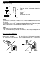
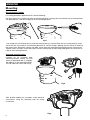
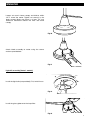
1
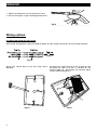
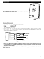
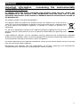
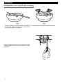
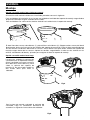
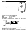
Instruction booklet
Manual de instrucciones
VORT VENTO
VORT VENTO
VORT VENTO L
COD. 5.471.084.170
VORTICE LATAM S.A.
3er Piso, Oficina 9-B, Edificio Meridiano
Guachipelín, Escazú, San José
PO Box 10-1251 Tel +506 2201 6242; Fax +506 2201 6239
COSTA RICA
[email protected]
02/04/2015
VORTICE ELETTROSOCIALI S.p.A.
Strada Cerca, 2 - frazione di Zoate
20067 TRIBIANO (MI)
Tel. (+39) 02-90.69.91
Fax (+39) 02-90.64.625
ITALIA
Table of Contents
Read the instructions contained in this booklet
carefully before using the appliance.
Vortice cannot assume any responsibility for
damage to property or personal injury resulting
from failure to abide by the instructions given in
this booklet.
Following these instructions will ensure a long
service life and overall electrical and mechanical
reliability.
Keep this instruction booklet in a safe place.
Safety . . . . . . . . . . . . . . . . . . . . . . . . . . . . . . . . . . 3
Before assembly . . . . . . . . . . . . . . . . . . . . . . . . . . 4
Preparing for installation . . . . . . . . . . . . . . . . . . . 4
Mounting braket installation . . . . . . . . . . . . . . . . . 5
Mounting . . . . . . . . . . . . . . . . . . . . . . . . . . . . . . . 6
Wiring options . . . . . . . . . . . . . . . . . . . . . . . . . . . 8
Operation and maintenance . . . . . . . . . . . . . . . . 10
Troubleshooting guide . . . . . . . . . . . . . . . . . . . . 10
Important information. . . . . . . . . . . . . . . . . . . . . . 11
Indice
Lea las instrucciones contenidas en este folleto
cuidadosamente antes de usar el aparato.
Vortice no asume ninguna responsabilidad por
daño a la propiedad, o lesión personal,
resultante de no cumplir las instrucciones dadas
en este folleto.
Seguir estas instrucciones le asegurará un
servicio de larga vida y confiabilidad eléctrica y
mecánica total.
Mantenga este instructivo en un lugar seguro.
2
EN
ES
Seguridad . . . . . . . . . . . . . . . . . . . . . . . . . . . . . . 12
Antes de montar . . . . . . . . . . . . . . . . . . . . . . . . . 13
Antes de la Instalación . . . . . . . . . . . . . . . . . . . . . 13
Instalación con soporte de montaje. . . . . . . . . . . 14
Montaje . . . . . . . . . . . . . . . . . . . . . . . . . . . . . . . . 15
Opciones de cableado . . . . . . . . . . . . . . . . . . . . . 17
Operación y mantenimiento . . . . . . . . . . . . . . . . . 19
Guía para solucionar problemas . . . . . . . . . . . . . 19
Información importante . . . . . . . . . . . . . . . . . . . . 20
ENGLISH
Safety
!
Warning:
this symbol indicates that care must
be taken to avoid injury to the user
• Be cautious. Read all instructions and safety information before installing your new fan. Review the
accompanying assembly diagrams.
• Fan should be mounted with at least 2,35 m of clearance from floor and all objects.
• Fan should be mounted in an area where it may come wet.
• Make sure that the fan voltage is compatible with your own electrical system.
• We recommend the installation be performed by a qualified Electrician who can check the strenght of the
supportive ceiling members and make proper electrical connection.
• All wiring must be in accordance with National and Local Electrical Codes and the ceiling fan must be
grounded as a precaution against possible ecectrical shock.
• To reduce the risk of fire, electrical shock, or personal injury, mount the outlet box marked “acceptable for fan
support”, and use the outlet screws provided with the outlet box. Most outlet boxes commonly used for the
supportof lighting fixtures are not acceptable for fan support and may need to be replaced. Consult a qualified
electrician if in doubt.
• To reduce the risk of fire, electrical shock, or personal injury, this fan must be mounted to an outlet box marked
suitable for fan support, and use mounting screws provided with the outlet box (mounting must support at
lesat 35 lbs.)
• To reduce the risk of fire or electrical shock, do not use this fan with any solid state fan speed control device,
or variable speed control.
• After making the wire connections, the wires should be spread apart with the grounded conductor and the
equipment-grounding conductor on one side of the outlet box and ungrounded conductor on the other side
of the outlet box and ungrounded conductoron the other side of the outlet box.
• Before you begin installing the fan, switch power off at service panel and lock service disconnecting means to
prevent power from being switched on accidentally. When the service disconnecting means cannot be locked,
securely fasten a prominent warning device, such as a tag, to the service panel.
• If this unit is to be installed over a tub or shower, it must be marked as appropriate for the application.
• Never place a switch were it can be reached from a tub or shower.
• The combustion airflow needed for safe operation of fuel-burning equipment may be affected by this unit’s
operation. Follow the heating equipment’s manufacturers guideline safety standards such as those published
by the National Fire Protection Association (NFPA), and the American Society for Heating, Refrigeration and
Air Conditioning Engineers (ASHRAE) and the local code authorities.
• Before servicing or cleaning unit, switch power off at service panel and lock service disconnecting means to
prevent power from being switched on accidentally. When the servicedisconnecting means cannot be locked,
securely fasten a prominent warning device, such as a tag, to the service panel !
Caution:
this symbol indicates that care must
be taken to avoid damaging the appliance
• Do not make modifications of any kind to this appliance.
• Use this unit only in the manner intended by the manufacturer. If you have any questions contact the
manufacturer.
• Installation work and electrical wiring must be done by qualified person(s) in accordance with all applicable
codes and standards (ANSI/NFPA 70-1996), including fire-rated construction.
• When cutting or drilling into wall or ceiling, do not damage electrical wiring and other hidden utilities.
• Make sure the installation site you choose allows the fan blades to rotate without any obstructions. Allow a
minimum clearance of 10 ft from the floor to the trailing edgeof the blade.
• Do not bend blade holders during installation to motor, balancing or during cleaning. Do not insert foreign
object between rotating blades.
• Attach the mounting bracket using only the hardware supplied with the outlet box. Fan is only to be mounteed
to an outlet box marked “Accettable for Fan Support”
• The ceiling fan should be connected to an isolated Main Switch with a contact opening of 3 mm 3
ENGLISH
Before assembly
1
5
3
1.
2.
3.
4.
5.
6.
2
4
Fig.1
Check to make sure that your carton contains all of the
parts mentioned in the parts list.
Note: when motor is taken out from carton, please put it on
a soft cloth, to avoid any damage on the ornamental
surface.
Mounting plate
Down rod
Canopy
Motor
Blades (3)
Blade holder (1 per blade)
6
Warning:
- To reduce the risk of electric schock or fire, do not use with any speed control device other than that packed
with the fan.
- To reduce the risk of personal injury, use only the two steel screws (and lock washer) provided with the fan
for mounting
- To reduce the risk of personal injury, do not bend the blade holders when installing the holders, balancing the
blades of cleaning the fan. Do not insert foreign objects in between rotating fan blades
- Please be sure cotter pin and bolt are in place and set screws on downrod are tightened securely before
operation
Caution
DO NOT MOUNT FAN TO SHEET ROCK OR DRYWALL ONLY.
In order to insure proper support, use two wood screws, to secure to a joist or beam. If the location you have
chosen doesn’t have a suitable support beam, install a 2” x 4” brace between ceiling joists to support fan.
Preparing for installation
Unpack and inspect fan carefully to be
certain all contents are included.
Turn off power at fuse box to avoid
possible electrical schock. Fig.2
4
Use metal outlet box suitable for fan support (must support 35
lbs). Before attaching fan to outlet box, ensure the outlet box is
secured fastened by at least two points to a structural ceiling
member (a loose box will cause the fan to wobble). Fig.3
ENGLISH
Mounting bracket installation
Fig.4
Fig.5
Remove the screws from the two mating holes (1) on
the canopy. Loosen (do not remove) the screws in
the mating slots (2) on the canopy.
Rotate the mounting bracket counter-clockwise and
remove from the canopy.
Install mounting bracket to outlet box in ceiling using
the screws and washers provided with the outlet box
Fig.6
5
ENGLISH
Mounting
Normal downrod option
If installing downrod supplied with fan, do the following:
For flush mount fans, carefully lift from the mounting bracket, making sure not to break any wire connections.
For downrod fans, slide the canopy up to the mounting bracket.
Fig.7
The canopy has two mating slots (1) and two mating holes (2). Position both slots on canopy directly under
and in line with two screws in the mounting brackets (3). Lift the canopy, allowing the two screws to slide into
the mating slots. Rotate the canopy until both screws from the mounting bracket drop into the slot recesses.
Tighten screws securely. Install two screws into the mating holes of the canopy abd tighten to secure the canopy to the mounting bracket. Extended downrod option
Carefully lift fan assembly onto
mounting bracket. Rotate fan until
notch on download ball (1) engages
the ridge (2) on the mounting bracket.
This will allow for hands free wiring.
Fig.8
With bracket holding fan assembly, make electrical
connections using the following step for wiring
instructions Fig.9
6
ENGLISH
Loosen set srew in lower canopy and slide to within
1/4”/7 mmof the motor. Tighten set screw(s) in the
lower canopy. Make sure there is at least 1/4” mm
clearance maintened around the mtor and lower
canopy Fig.10
Attach blade assembly to motor using the screws
washers providedand Fig.11
Light Kit assembly (Vento L models)
Install the light bulb (not provided), E14, 2x40 W max.
Fig.12
Install the glass-globe onto the lamp filter
Fig.13
7
ENGLISH
1. Tighten the decorative nut and washer by hand
2. Do not over tighten as glass breakage could occur
1
Fig.14
2
3
Wiring options
Installing and wiring the wall control
Wall control wiring options: follow the diagram below to make wiring connections for wall control operation. Fig.15
Mount wall control base to the wall using screws
provided
Fig.16
8
Connect black supply wire (6) to the “A” position and
the black fan wire (7) to the “F” position on the
terminal block (8), and tighten the terminal block
screws (VENTO MODELS)
Fig.17
ENGLISH
Mount wall control cover to the wall control base using screws provided. Attach the decorative caps into the screws.
Fig.18
Wiring the VENTO L models
1. There are four color wires coming from the top of motor.
BLUE
:live wire for light
BLACK
:live wire for fan
WHITE
:neutral wire
YELLOW/GREEN :ground wire
2. Connect the fan wires and ceiling wires with the junction box (terminal block) which mounted on the clamp.
Black to the live, Blue to the live, White to the neutral, and Yellow/Green to the ground. Always connect the
gound wire(yellow/green in colour) first.
Blue
Light Control
(Not provided)
Black
Speed
Control
White
Line Phase
~
Neutral
Yellow-Green
Ground
Motor
Fig.19
3. Connect with wall mounted control box (according to scheme). Be sure thet the wire diameter should at least
0,75 mm2, H05VVH (or SPT-2) grade is recommended. The speed is controlled by the control box. Rotate the
switch to your favorite position.
CAUTION: this fan should be installed and connected by a qualified electrician.
WARNING: to reduce the of electric shock or fire, don’t use with any speed control device other than that
packed with the fan. 9
ENGLISH
Operation and maintenance
Operation
Turn on the power and check operation of fan. The wall control controls the fan speeds as follows: 0 - Off, 1 High, 2 - Medium, 3 - Low. Speed settings depend on factors such as room size, ceiling height, number of fans
and so on. Maintenance
1. Because of the fan’s natural movement, some connections may become loose. Chek the support
connections, brackets, and blade attachmentstwice a year. Make sure they are secure.
2. Clean your fan periodically to help maintain its new appearance over the years. Do not use water when
cleaning. This could damage the motor, or the wood, or possibly cause electrical shock.
3. Use only a soft brush or lint-free cloth to avoid scratching the finish. The plating is sealed with a lacquer
coating to minimize discoloration or tarnishing.
4. There is no need to oil your fan. The motor has permanently lubricated bearings.
Troubleshooting guide
If you have difficulty operating your new ceiling fan, it may the result of incorrect assembly, installation, or
wiring. In some cases, these installation errorsmay be mistaken for defects. If you experience ant faults, please
check this Trouble Shooting Chart. If a problem cannot be remedied, please consult with your authorized
electrician and do not attemptany electrical rapairs yourself.
TROUBLE
SUGGESTED REMEDY
1. If fan does not start:
1. Check main and branch circuit fuses or circuit breakers.
2. Check wire connections as performed in step #8 or #13 of installation.
CAUTION: make sure main power is turned off.
3. If the fan still will not start, contact a qualified electrician. Do not
attempt to troubleshoot internal electrical connections yourself.
2. If fan sounds noisy:
1. Check to make sure all screws in motor housing are snug (not over
tightened).
2. Check to make sure the screws wich attach the fan blade holder to
the motos are tight.
3. some fan motors are sesitive to signals from Solid State variable
speed controls. Don’t use a Solid State variable speed control.
4. Allow “break-in” period of 24 hours. Most noises associated wirh a
new fan will disappear after this period.
3. If fan wobbles
The following procedures should eliminate most of the wobble. Check
for wobble after each step.
1. Check that all blade holders are tightened securely to motor
2. Make sure that canopy and mounting bracket are tightened securely
to ceiling joist.
3. If blade wobble is still noticeable, interchanging two adjacent (side by
side) blades can redistribuite the weight and possibly result in
smoother operation.
10
ENGLISH
Important information
compatible disposal
concerning
the
environmentally
IN CERTAIN EUROPEAN UNION COUNTRIES THIS PRODUCT DOES NOT FALL WITHIN THE
REQUIREMENTS OF THE NATIONAL LAWS IMPLEMENTING DIRECTIVE WEEE, AND IN THESE
COUNTRIES THE PRODUCT IS NOT SUBJECT TO SEPARATE DISPOSAL OPERATIONS AT THE END OF
ITS WORKING LIFE.
This product conforms to EU Directive2002/96/EC.
This appliance bears the symbol of the barred waste bin. This indicates that, at the end of its
useful life, it must not be disposed of as domestic waste, but must be taken to a collection centre
for waste electrical and electronic equipment, or returned to a retailer on purchase of a
replacement. It is the user's responsibility to dispose of this appliance through the appropriate channels at the
end of its useful life. Failure to do so may incur the penalties established by laws governing waste
disposal. Proper differential collection, and the subsequent recycling, processing and environmentally compatible
disposal of waste equipment avoids unnecessary damage to the environment and possible related healthrisks,
and also promotes recycling of the materials used in the appliance. For further information on waste collection and disposal, contact your local waste disposal service, or the shop
from which you purchased the appliance. Manufacturers and importers fulfil their responsibilities for recycling, processing and environmentally
compatible disposal either directly or by participating in collective systems.
11
ESPAÑOL
Seguridad
!
Atención:
este simbolo indica precauciones que sirven
para evitar daños al usuario
• Tenga cuidado! Lea todas las instrucciones y la información de seguridad antes de instalar su ventilador
nuevo. Revise los diagramas de montaje incluidos.
• El ventilador debe ser montado con al menos 2,35 m de espacio desde el piso y desde todos los demás
objetos.
• El ventilador debe ser montado en un área que pueda humedecerse.
• Asegúrese de que el voltaje del ventilador sea compatible con el de su propio sistema eléctrico.
• Recomendamos que la instalación sea realizada por un electricista calificado que pueda chequear la fortaleza
de los elementos de soporte del cielo raso y hacer las conexiones eléctricas apropiadas.
• Todo el cableado debe estar en conformidad con las Normas de Electricidad Nacionales y Locales, y el
ventilador del cielo raso debe estar polarizado como precaución contra posibles choques eléctricos.
• Para reducir el riesgo de incendio, descarga eléctrica o lesiones personales, monte el ventilador en una caja
de embutir rotulada “adecuata para ventiladores” y utilice los tornillos de montaje incluidos con la caja de
embutir. La mayoría de las cajas de embutir utilizadas normalmente para artefactos de illuminación no son
adecuadas para ventiladores y deberían ser reemplazadas. Si tiene preguntas, consulte a un electricista
certificado. • Para reducir el riesgo de incendios, choques eléctricos o lesiones personales, este ventilador se debe montar
sobre una caja de embutir que tenga una marca que indique que es adecuada para soportar un ventilador.
Además debe utilizar los tornillos correspondientes incluidos con la caja de imbutir. (El montaje debe soportar
por lo menos 35 libras).
• Para reducir el riesgo de incendios o choques eléctricos, no use este ventilador con un dispositivo de control
de velocidad de stedo sólido para ventilador, o un control de velocidad variable.
• Déspues de hacer las conexiones, se deben separar los cables: el conductor de puesta a tierra y el conductor
de puesta a tierra del equipo a un lado della caja de imbutir, y el conductor que no tiene puesta del otro lado
de la misma.
• Antes de comenzar a instalar el ventilador, apague la alimentación en el panel de servicio y bloque el medio
de desconexión del servicio para evitar que se encienda accidentalmente. Cuando no se puede bloquear el
medio de desconexión del servicio eléctrico, fije de manera segura y un dispositivo de advertencia prominente,
como un rótulo, al panel de servicio.
• Si esta unidad se instalará sobre una bañera o una ducha, debe estar identificada como adecuada para ese
tipo de aplicación.
• Nunca coloque un interruptor donde se pueda alcanzar desde una bañera o una ducha. • Es posible que la operación de esta unidad afecte el flujo de aire de combustión necesario para la operación
segura de equipo que quema combustible. Siga la directrices de seguridad del fabricante de equipo de
calefacción como las publicadas por la Asociación Nacionalde Protección Contra Incendios, y la Sociedad
Americana para ingenieros de Calefacción, Refrigeracion y Aire Acondicionado , y las autoridades del código
local. • Antes de efectuar tareas de servicio o limpieza en la unidad, apague la alimentación en el panel de servicio y
bloquee el medio de desconexión del servicio para evitar que se incienda accidentalmente. Cuando no se
puede bloquear el medio de desconexión del servicio eléctrico, fije de manera segura y un dispositivo de
advertencia prominente, como un rótulo, al panel de servicio. !
Advertencia:
este simbolo indica precauciones que sirven
para evitar daños en el producto
• No haga modificaciones de ningún tipo a este aparato.
• Use este unidad sólo de la manera en que el fabricante quiere que se haga. Si tiene dudas, llame al
fabricante.
• El trabajo de instalación y el cableado eléctrico los deben efectuar personas calificadas cumpliendo con
todos los códigos y las normas aplicables (ANSI/NFPA 70-1996), incluyendo las de incendio.
• Al cortar o perforar una pared o el cielo raso, no dañe el cableado electrico y otras instalaciones de servicios
públicos ocultos.
• Asegúrese de que el sitio para la instalación que escoja permita que el ventilador gire libremente sin
obstrucciones. Deje un espacio minimo de 10 pies desde le piso hasta el borde posterior de la paleta. • No doble los soportes para las paletas durante la instalación al motor, al balancear o durante la limpieza. No
inserte objetos extraños entre las paletas mientras giran.
• Fije el soporte de montajeusando solo la tornilleria suministrada con la cajade embutir. El ventilador solo se
debe montar en una caja de embutir marcada “Accettable for Fan Support” (aceptable para soportar
ventiladores).
• El ventilador del cielo raso debe estar conectado a un Switch Principal Aislado con una abertura de contacto
de 3 mm.
12
ESPAÑOL
Antes de montar
1
5
3
1.
2.
3.
4.
5.
6.
2
4
Fig.1
Asegúrese de que su caja contiene todas las partes
mencionadas en la lista.
Nota: cuando el motor sea sacado de la caja, por favor
colóquelo sobre una tela suave para evitar cualquier daño
a la superficie ornamental.
Platina de montaje Barra inferior Cubierta (toldo)
Motor
Cuchillas (3)
Retenedor de cuchillas (1 por cada cuchilla)
6
Advertencia:
- Para reducir el riesgo de choque eléctrico o fuego, no use ningún dispositivo de control de velocidad aparte
del que viene empacado con el ventilador.
- Para reducir el riesgo de lesión, use solo los dos tornillos de acero (y arandela a presión) proveídos con el
ventilador para el montaje.
- Para reducir el riesgo de lesión personal, no doble los retenedores de las cuchillas al instalarlos, balanceando
las cuchillas de limpieza del ventilador. No inserte objetos extraños entre las cuchillas de rotación.
- Por favor, asegúrese de que el pin de cuña y el perno estén en el lugar adecuado y coloque los tornillos sobre
sobre la barra inferior herméticamente asegurados antes de la operación.
Precaución:
NO MONTE EL VENTILADOR SOLAMENTE SOBRE YESO-CARTÓN O FIBROLIT
Para poder asegurar el soporte adecuado, use dos tornillos de madera para asegurarlos a una junta o a una
viga. Si el lugar que usted ha escogido no tiene una viga adecuada de soporte, instale una pieza de refuerzo
de 2” x 4” entre las vigas del cielo raso para dar más soporte.
Antes de la instalación
Quite el envoltorio e inspeccione
detenidamente el ventilador para verificar
que todas las piezas estén incluidas.
Apague la alimentación en la caja de
fusibles para evitar la posibilidad de
descarga eléctrica Fig.2
Use una caja de imbutir de metal adecuada para soportar un
ventilador (debe soportar 35 libras).
Antes de fijas el ventilador a la caja de imbutir asegúrese de
que la misma esté fijada de manera segura en por lo menos
dos puntos a un miembro estructural del cielo raso (una caja
suelta haria que el ventilador oscile) Fig.3
13
ESPAÑOL
Instalación con soporte de montaje
Fig.4
Quite los tornillos de los dos orificios coincidentes
(1) del dosel. Afloje (no quite) los tornillos de las
ranuras coincidentes (2) del dosel.
Fig.5
Gire el soporte de montaje y sepárelo del dosel Instale el soporte de montaje a la caja de embutir del
cielorraso con la tornilleria suministrada con la caja
de embutir. Fig.6
14
ESPAÑOL
Montaje
Opción con varilla vertical para cielorraso normal
Si instala la varilla vertical incluida con el ventilador, proceder como en la siguiente
Para ventiladores de instalación al ras, levante con cuidado el ventilador del soporte de montaje asegurándose
de que no interrumpa ninguna conexión de los cables.
Para ventiladores con varilla vertical, deslice el dosel hacia arriba hasta el soporte de montaje.
Fig.7
El dosel tiene dos ranuras coincidentes (1) y dos orificios coincidentes (2). Coloque ambas ranuras del dosel
directamente abajo y en linea con los dos tornillos del soporte de montaje (3). Eleve el dosel, permitiendo que
los dos tornillos se deslicen dentro de las ranuras. Gire el dosel hasta que ambos tornillos del soporte de
montaje caigan dentro de las ranuras. Apriete los tornillos asegurándolos. Instale los dos tornillos en los
orificios coincidentes del dosel y ajústelos para asegurar el dosel al soporte de montaje. Opción con varilla vertical mas larga
Levante con cuidado el conjunto del
ventilador hasta el soporte de montaje.
Gire el ventilador hasta que la muesca
de la bola de la varilla vertical (1) calce
sobre la saliente del soporte de
montaje (2). De este modo, tendrá las
dos manos libres para hacer el
cableado.
Fig.8
Con la pieza de montaje sujetando el conjunto del
ventilador, haga las conexiones eléctricaso de
acuerdo a las siguentes instrucciones de cableado. Fig.9
15
ESPAÑOL
Afloje el tornillo de fijacion en el dosel inferior y
deslicelo a 7 mm del motor. Ajuste el (los) tornillo (s)
de fijación en el dosel inferior. Asegúrese de que haya
un espacio de por lo menos 7 mm alrededor del motor
y el dosel inferior. Fig.10
Fije el conjunto de las paletas al motor usando los
tornillos y las arandelas incluidos.
Fig.11
Juego liviano de armado (Modelo Vento L)
Instale la bombilla clara (no proveída), E14, 2x40 W máx.
Fig.12
Instale el globo de vidrio en el filtro de la lámpara.
Fig.13
16
ESPAÑOL
1. Soque la tuerca decorativa y la arandela a mano
2. No soque demasiado ya que el vidrio podría
quebrarse.
1
Fig.14
2
3
Opciones de cableado
Instalación y cableado del control de pared
Cableado para control de pared: siga las instrucciones del diagramma siguiente para hacer las conexiones de
cableado para el ventilador con control de pared. Fig.15
Instale la base del control de pared sobre la pared con Conecte el alambre negro de la fuente (6) a la posicion
“A”, el alambre negro del ventilador (7)a la posición
los tornillos incluidos.
“F” del bloque de termilanes (8) y apriete los tornillos
del bloque de terminales. (MODELOS VENTO)
Fig.16
Fig.17
17
ESPAÑOL
Instale de control de pared cubierta a la base del control de pared con los
tornillos incluidos. Fije las tapas decorativas (1) a los tornillos. Fig.18
Cablee los modelos VENTO L
1. Hay 4 colores de cables viendo desde la parte superior del motor.
AZUL
:cable vivo para la luz NEGRO
:cable vivo para el ventilador BLANCO
:cable neutro
AMARILLO/VERDE
:cable de tierra 2. Conecte los cables del ventilador y los cables del cielo raso a la Caja de Conexiones (block terminal) que
están montados sobre la abrazadera. El NEGRO al vivo, el AZUL al vivo, el BLANCO al neutro, y el
AMARILLO / VERDE a la tierra. Conecte primero siempre el cable de polarización (amarillo / verde).
Blue
Light Control
(Not provided)
Black
Speed
Control
White
Line Phase
~
Neutral
Yellow-Green
Ground
Motor
Fig.19
3. Conecte con la caja de control montada a la pared (de acuerdo al esquema). Asegúrese de que el diámetro
del cable sea al menos 0,75 mm2. Se recomienda el grado H05VVH (o SPT-2). La velocidad es controlada
por la Caja de Control. Rote el switch a su posición favorita.
PRECAUCIÓN: Este ventilador debe ser instalado y conectado por un electricista calificado.
ADVERTENCIA: Par reducir el riesgo de choque eléctrico o fuego, no use ningún dispositivo de control de
velocidad diferente al que se provee con el ventilador. 18
ESPAÑOL
Operación y mantenimiento
Operación
Encienda el ventilador y verifique su funcionamiento. El control de pared regula las velocidades de la siguiente
manera: 0 - Apagado, 1 - Alta, 2 - Mediana, 3 - baja. Las velocidade para clima cálido o frío dependen de
factores como el tamaño de la habitación, la altura del ventilador, el número de ventiladores, etc. Mantenimiento
1. El movimiento natural del ventilador podría hacer que se aflojen algunas conexiones. Verifique las
conexiones de soporte, las piezas de fijación y los accesorios de las paletas dos veces al año. Cerciórese
de que estén aseguradas. 2. Limpie el ventilador periódicamente para ayudar a mantener su aparencianueva con el correr de los años.
No use aqua para limpiarlo, ya que podría dañar el motor o la madera o causar descarga eléctrica.
3. Use sólo un cepillo blando o un trapo sin pelusa para no rayar el acabado. El enchapado está sellado con
una capa de laca para minimizar la decoloración o pérdida del brillo. 4. No hay necesidad de aceitar el ventilador. El motor tiene cojinetes de lubricación permanente.
Guía para solucionar problemas
Si tiene difficultades para hacer funcionar su nuevo ventilador, podría ser a causa del armado, instalación o
cableado incorrectos. En algunos casos, estos errores de instalación podrían ser cunfundidos con defectos.
Si experimenta alguna falla, consulte esta guía para solucionar problemas. Si no puede solucionar el problema
, consulte a un electricista autorizado y no intente reparar conexiones eléctricas. PROBLEMA
SOLUCION SUGERIDA
1. Si el ventilador no se eciende:
1. Compruebe los fusibles o disyuntores principales y del circuito derivado.
2. Compruebe el cableado del bloque de terminales como lo hizo en el paso
No. 8 o 13 de la instalación. ADVERTENCIA: asegúrese de que la
alimentación principal esté apagada.
3. Si el ventilador no arranca, póngase en contacto con un électricista
calificado. No intente reparar conexiones eléctricas internas.
2. Si el ventilador es ruidoso:
1. Compruebe para asegurarse de que todos los tornillos del alojamiento del
motor estén ajustados (no los apriete demasiado).
2. Compruebe para asegurarse de que los tornillos que fijan el soporte de la
paleta del ventilador al motor estén apretados.
3. Algunos motores de ventilador son sensibles a las senales de loso
controles de velocidad variable de estado solido para motores. NO USE un control de velocidad variable de estado sólido.
4. Permita el “rodaje” del ventilador durante ujn periodo de 24 horas. La
mayoria de los ruidos asociados con el ventilador nuevo desaparecerán
después de este período
3. Si el ventilator vibra:
Los siguentes procedimientos deberían eliminar la mayoría de los problemas
de oscilación. Verifique la oscilación después de cada paso. 1. Verifique que todos los soportes de las paletas estén firmemente
aseguradas al motor.
2. Asegúrese de que el dosel y el soporte de montaje estén firmemente
asegurados a la viga del cielorraso.
3. Si la oscilacion de la paleta sigue siendo visible, es posible que al
intercambiar dos paletas adyacentes (lado a lado) se redistribuya el peso
y el funcionamiento sea más suave.
19
ESPAÑOL
Información importante sobre eliminación respetuosa con el
medio ambiente
EN ALGUNOS PAÍSES DE LA UNIÓN EUROPEA ESTE PRODUCTO NO ESTÁ INCLUIDO EN EL ÁMBITO
DE APLICACIÓN DE LA LEY NACIONAL QUE TRASPONE LA DIRECTIVA RAEE Y, POR LOTANTO, NO
EXISTE OBLIGACIÓN ALGUNA DE RECOGIDA SELECTIVA AL FINALIZAR SU VID AÚTIL.
Este producto cumple los requisitos de la Directiva EU2002/96/EC.
El símbolo del contenedor de basura tachado, que hay sobre el aparato, indica que no puede ser
eliminado con los desechos domésticos al finalizar su vida útil. Se ha de llevar a un punto de
recogida selectiva para aparatos eléctricos o electrónicos o entregar al proveedor durante la
compra de un aparato equivalente.
El usuario deberá llevar el aparato a un punto de recogida selectiva para su eliminación, de lo
contrario se aplicarán las sanciones previstas por las normas sobre eliminación de desechos.
La recogida selectiva para la reutilización, tratamiento y eliminación respetuosa con el medio ambiente del
aparato ayuda a evitar los efectos sobre el medio ambiente y la salud y favorece el reciclaje de los materiales
que componen el producto.
Para más información sobre los sistemas de eliminación disponibles, contactar con el servicio local de
eliminación de desechos o con la tienda que vendió el aparato.
Los fabricantes y los importadores cumplen con su responsabilidad de recuperación, tratamiento y eliminación
respetuosa con el medio ambiente directamente o participando a un sistema colectivo.
Vortice Latam reserves the right to make improvements to products at any time and without prior notice.
Vortice se reserva el derecho de incorporar todas las mejoras necesarias a los productos en fase de venta.
20
ESPAÑOL
21
1
GARANTIA - GUARANTEE
SELLO DEL DISTRIBUIDOR
PARA SER CONSERVADO
name and address of supplier
to be retained
AÑOS
22
YEARS
EMPAQUE
_________________
PRUEBA
FECHA DE ENVÍO
Mailing date
__________________
Para ejercer la garantía , el Cliente debe completar y devolver a VORTICE LATAM ,
dentro de los 8 días posteriores a la compra , la "Parte 2 " de la Garantía , la
dirección y en la forma prevista en esta parte . La "Parte 1 " de la tarjeta de garantía
debe ser conservada y presentada, junto con el documento scal (factura o recibo)
expedida por el vendedor en el momento de la compra, al Servicio Post-Venta de
Vortice Latam , que realizará el trabajo de garantía . Los servicios prestados en
garantía no amplían el período de garantía.
The “Part 1” must be attached to the appliance when it needs to be returned for
servicing.
ATTENTION Guarantee is only valid if all details are completed correctly.
Exclusiones
Esta garantía no cubre:
• Los daños causados por el transporte.
• Defectos o daños derivados del uso incorrecto o inadecuado por parte del cliente.
• Defectos causados por no seguir las advertencias y condiciones de uso, como se indica en el
manual de instrucciones que acompaña al producto.
• Los defectos resultantes de la instalación incorrecta o por una instalación sin cumplir con las
disposiciones de la sección correspondiente del manual de instrucciones.
• Las fallas causadas por una mala conexión a la red eléctrica o tensión de alimentación distinta
a la especi cada para esta unidad.
Esta garantía no cubre, además, los posibles defectos derivados del mantenimiento o
reparaciones de cientes realizadas por personal no cali cado o por terceros no autorizados.
2
GARANTIA - GUARANTEE
SELLO DEL DISTRIBUIDOR
PARA ENVIAR
name and address of supplier
DENTRO DE LOS 8 DÍAS POSTERIORES A LA COMPRA
to send (within 8 days from date of purchase)
AÑOS
22
YEARS
DATOS DEL USUARIO/CUSTOMER DATA
nombre/name _____________________________________________________________
apellido/surname ________________________________________________________
calle/street _____________________________________________________________
código postal/post code ___________________________________________________
ciudad/town ______________________________________________________________
Declaro tener conocimiento de las condiciones de garantía especi cadas en el
certi cado en mi poder y autorizo el manejo de mis datos personales.
Firma/signed _____________________________________________________________
(Por favor escriba con letra de molde/please use block letters)
FECHA DE ENVÍO
Mailing date
ARTICULO COMPRADO EN
Date of purchase
___________________________________
_______________________________
LATAM AREA
OTHER COUNTRIES
Enviar por favor la garantía a la dirección:
Vortice Latam S.A.
3er Piso, O cina 9-B
Edi cio Meridiano
Guachipelín, Escazú
San José, Costa Rica
PO Box 10-1251
Please send the guarantee to the retailer’s
address in the country where the appliance
has been purchased.
Autorizo a Vortice E l e t t r o s o c i a l i
S.p.A. y a los distribuidores de los
productos Vortice a incluir mis datos
en sus listas y comunicarlos a
terceros para el envío de material
publicitario e informativo. En todo
momento, según las leyes vigentes
en mi país, podré tener libre acceso
a mis datos, pedir su modi cación o
cancelación o bien oponerme a su
utilización escribiendo a la dirección
del revendedor del país donde el
aparato ha sido adquirido.
No autorizo
(marcar si interesa).
I authorise Vortice Elettrosociali
S.p.A. and its local distributors to
include my personal details within
their database and they can
use
it through a third party for the
despatch of advertising material. At
any time, in accordance with the
regulations in force within my
country. I can have access to details
and can ask to make changes, or
prohibit the usage of my details.This
will be done by addressing my
request directly to the headquarters
of the local distributor where the
appliance has been bought.
I do not authorize
(please tick here if required).