1
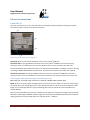
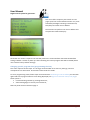
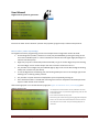
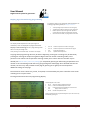
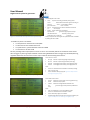
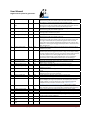
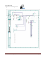
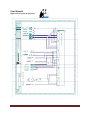
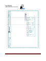
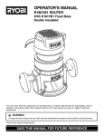
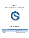
User Manual Digital control system for generators FISCHER PANDA GENERATORS, INC. 4345 NE 12 Terrace, Oakland Park, Florida 33334 Toll-free (800) 508-6494 - Phone (954) 462-2800 - Fax (954) 462-2801 E-Mail: [email protected] -Web Site: www.fischerpanda.com Document release 001/ July 2013 Page 1 User Manual Digital control system for generators Contents Scope of this document ................................................................................................................................ 5 System components ...................................................................................................................................... 5 Power supply ................................................................................................................................................. 5 Dimensions .................................................................................................................................................... 5 Panel GP170 .............................................................................................................................................. 5 Buttons on panel front side: ................................................................................................................. 7 VCS 171: .................................................................................................................................................... 7 Electrical connections ................................................................................................................................... 8 Panel GP170 .............................................................................................................................................. 8 Cable length, cable type and usage restrictions (GP170) ..................................................................... 8 VCS171 ...................................................................................................................................................... 9 Wiring the system, linking components ....................................................................................................... 9 Operating the system .................................................................................................................................. 10 Power up / power down, main displays ................................................................................................. 10 Manual power on / off ........................................................................................................................ 10 Remote power on / off ....................................................................................................................... 10 Initial display: .......................................................................................................................................... 10 Display 1: Electrical readings ................................................................................................................... 11 Display 2: Temperature and oil pressure readings: ................................................................................ 11 Display 3: Miscellaneous readings: ......................................................................................................... 12 Display 4: Panel settings ......................................................................................................................... 12 Clear text messaging ............................................................................................................................... 12 Acoustic alarm, alarm output, alarm mute ............................................................................................. 13 Operating the generator ............................................................................................................................. 14 Start / stop the generator ....................................................................................................................... 14 Demand mismatch .................................................................................................................................. 14 Successful start ....................................................................................................................................... 14 Document release 001/ July 2013 Page 2 User Manual Digital control system for generators Unsuccessful start ................................................................................................................................... 14 Unlatching from emergency stop or unsuccessful start lock‐up ........................................................ 15 Over‐cranking .......................................................................................................................................... 15 Emergency shutdowns ............................................................................................................................ 15 Unlatching from emergency stop or unsuccessful start lock‐up ........................................................ 15 Running the generator ............................................................................................................................ 16 How generator control works ............................................................................................................. 16 What is monitored .............................................................................................................................. 16 Special features of Fischer Panda Control System ...................................................................................... 18 Accessing /altering control settings ........................................................................................................ 18 Reset to default ................................................................................................................................... 18 Changing specific program data (programming the VCS) ................................................................... 19 How to alter / enter any settings ........................................................................................................ 20 Display pages shown during programming ......................................................................................... 21 Reading log data ..................................................................................................................................... 25 Understanding the concept of logging data ....................................................................................... 25 Retrieving log data .................................................................................................................................. 26 Messages displayed by the panel ............................................................................................................... 28 Trouble shooting guidance ......................................................................................................................... 30 Some common problems encountered in the past: ............................................................................... 30 Revision History .......................................................................................................................................... 32 Appendix 1: VCS171 Wiring Diagram .......................................................................................................... 33 Document release 001/ July 2013 Page 3 User Manual Digital control system for generators TABLE 1: ANALOG INPUTS PROCESSED BY CONTROL SYSTEM .................................................................................... 17 TABLE 2: BINARY (DIGITAL) AND MISCELLANEOUS INPUTS PROCESSED BY CONTROL SYSTEM ................................. 17 TABLE 3: PANEL MESSAGES ......................................................................................................................................... 28 FIGURE 1: PANEL DIMENSIONS...................................................................................................................................... 6 FIGURE 2: PANEL, FRONT SIDE....................................................................................................................................... 7 FIGURE 3: VCS171 MOUNTING BOX .............................................................................................................................. 7 FIGURE 5: PANEL REAR SIDE; CONNECTOR ASSIGNMENT ............................................................................................. 8 FIGURE 8: INITIAL PANEL DISPLAY ............................................................................................................................... 10 FIGURE 9: DISPLAY 1, GENERATOR OUTPUT ............................................................................................................... 11 FIGURE 10: DISPLAY 2, TEMPERATURES AND OIL PRESSURE ...................................................................................... 11 FIGURE 11: DISPLAY 3, POWER OUTPUT, MISCELLANEOUS ........................................................................................ 12 FIGURE 12: DISPLAY 4, PANEL SETTINGS ..................................................................................................................... 12 FIGURE 13: SELECTION MENU, FIRST PAGE ................................................................................................................. 19 FIGURE 14: PANEL CONFIRMING RESET TO DEFAULT ................................................................................................. 19 FIGURE 15: SELECTION MENU, SECOND PAGE ............................................................................................................ 20 FIGURE 16: START VCS PROGRAMMING ..................................................................................................................... 20 FIGURE 17: TEMPERATURE SETTINGS I........................................................................................................................ 21 FIGURE 18: TEMPERATURE SETTINGS II....................................................................................................................... 21 FIGURE 19: OIL AND SEA WATER PRESSURE AND SPEED SETTINGS ............................................................................ 22 FIGURE 20: MAIN OUTPUT VOLTAGE AND BATTERY VOLTAGE ................................................................................... 22 FIGURE 21: POWER AND CURRENT OUTPUT ............................................................................................................... 22 FIGURE 22: DELAY TIMES FOR WARNINGS/ EMERGENCY STOP .................................................................................. 23 FIGURE 23: RESISTANCE FOR TANK SENSOR AND ALARM LEVEL ................................................................................ 23 FIGURE 24: CONTROL SETTINGS PAGE I ...................................................................................................................... 23 FIGURE 25: CONTROL SETTINGS PAGE II ..................................................................................................................... 23 FIGURE 26: CONTROL SETTINGS PAGE III .................................................................................................................... 24 FIGURE 27: SPEED, CRANKING TIME AND IDLING TIME .............................................................................................. 24 FIGURE 28: VCS OPTIONS TO BE ENABLED/DISABLED, PAGE I .................................................................................... 24 FIGURE 29: VCS OPTIONS TO BE ENABLED/DISABLED, PAGE II ................................................................................... 25 FIGURE 30: LAST PAGE IN PROGRAMMING MODE ..................................................................................................... 25 FIGURE 31: INVALID MEMORY ACCESS ........................................................................................................................ 27 FIGURE 32: TERMINATING DATA LOG READING. ........................................................................................................ 27 FIGURE 33: DATA SET READY TO BE DISPLAYED .......................................................................................................... 27 Document release 001/ July 2013 Page 4 User Manual Digital control system for generators Scopeofthisdocument This document addresses the electronic control of asynchronous generators with digital control system made by Fischer Panda. It is an operator’s manual strictly applying to electronic control unit and HMI (user interface). For any questions related to the diesel engine, fuel system, cooling system … see the generator manual. This document will address manual operation of the system only. Alternatively the generator may be remotely operated via its NMEA2000 communication port. For understanding how this works see document “NMEA 2000 interface on GP170”, most recent release number. Systemcomponents The system is built of two components: Graphic panel, part number GP1702, commonly referred to as “panel”. Provides HMI and also NMEA2000 connectivity. The entire control system is accessed via this device. Control, monitoring and load sensing device, part number VCS171, commonly referred to as “VCS” (VCS= Voltage Control System). This component performs the entire generator and diesel engine monitoring and control along with sensing the output current and voltage. Powersupply The entire assembly will work within a voltage range of 12…36 V DC. Power is supplied to the VCS only which in turn feeds the other devices. Usually the system is fed from the generator starter battery. Generator AC output voltage as well as output current is potential free from this power supply with insulation strength of 4000V. As required by NMEA2000 standard the panel has a potential free NMEA 2000 port working within the limits specified by applicable standards (9...16V). Load equivalency of this port is 1. Dimensions PanelGP170 The panel may be mounted in a wall, bulkhead or boat’s operation panel. See Figure 1: Panel dimensions (next page) for required mounting space. All panel connectors are on the rear side. Document release 001/ July 2013 Page 5 User Manual Digital control system for generators Figure 1: Panel dimensions Document release 001/ July 2013 Page 6 User M Manual Digital co ontrol system m for generaators Buttonssonpanelffrontside: LEDss on panel faceplaate: D1, abovee button S1: Show ws whether entiree system is powered o on (when on) or n not (LED off). D2, abovee button S5: Show ws generator statu us: o When off: Geneerator is stopped o When on: Geneerator is running o When blinking: Generator is tran nsitioning from start to stop or vice versa Butttons on panel faceplate: S1: Used to manually pow wer up or down en ntire system S2: Turnss off acoustic alarm m S3: Flips tto next screen S4: Variou us assignments. R Read this manual tto learn about. S5: Manuaally start / stop th he generator. Notee: During special interaction (reading log data, proggramming the VCS,, …) buttons S2 to o S5 may also havve other functionss assigned Read d this manual to llearn about. Figure 2: P Panel, front side e VCS17 71: The VCS is mounted inside the geenerator capssule. It is con ntained withiin a box on the service sid de of the or. The VCS171 is mounteed inside thee box below. generato Figure 3: V VCS171 Mounting Box . Documeent release 0 001/ July 2013 Page 7 User Manual Digital control system for generators Electricalconnections PanelGP170 All panel connectors are on the rear side and are of the type header (board) with mating jack (cable). The cable connector always is the female connector. J9 J8 J10 J1 Figure 4: Panel rear side; connector assignment Connector J1 has screw clamps suitable for wires up to 0.75mm2/AWG 18. Connector J10 has spring loaded terminals for wires up to 0.5mm2/AWG22. To unlock the spring connector insert a screwdriver in the inner slot. Now the wire may be inserted in the outer slot. Fischer Panda offers drop cables that match into J10 header with MICRO‐C or MINI‐C connector, pinning according to NMEA 2000 hardware specification. Contact Fischer Panda if such cables are required. Connectors J8 and J9 have spring loaded terminals for wires up to 0.75mm2/AWG18. To unlock the spring connector insert a screwdriver in the inner slot. Now the wire may be inserted in the outer slot. Cablelength,cabletypeandusagerestrictions(GP170) J10: Cable type and cable length limitations as defined in NMEA 2000 standard apply. J9/J8: J9 serves as power supply for digital inputs on J8. It must not be used as a common power supply or junction point. See wiring diagram for more specific example on how to wire these. Maximum cable length very much depends on the type of switching device that is used and is recommended not to exceed 300 feet. J1: This is the serial data link to the VCS, includes power supply and a signal that triggers the VCS on/off. Maximum cable length is 300feet; Cables longer than 30 feet shall be shielded with shield connected to supply ground on one end. Cable shall be at least 5x0.75mm2 / AWG 18. Document release 001/ July 2013 Page 8 User Manual Digital control system for generators VCS171 Below sketch shows the control device VCS171, its connectors with the first pin number. See wiring diagram in Appendix for wiring details. Figure 5: VCS171 Connector Labeling Wiringthesystem,linkingcomponents Generators are shipped ready wired for usage. After installing the panel it needs to be connected to the VCS (plug in J1 on the panel). Connecting the panel and the generator output usually is the only electrical connection that needs to be done in the field. All components come ready wired with the generator. It is beyond the scope of this document to give a detailed description on wiring details. See the wiring diagram for a complete schematic of generator and control system wiring. Document release 001/ July 2013 Page 9 User M Manual Digital co ontrol system m for generaators Opera atingthesystem Powerrup/pow werdown,,maindisplays The entire system maay be powered on or off by either maanual or remote access. N Note the panel needs nd thus chan nging betweeen the two m modes will req quire the pan nel to be swaapped. differentt firmware an Manuallpoweron//off To poweer the system m up or turn it off simply p press button S1, On/Off o on the panel. Doing so wiill toggle the actual status. Wh hen powered d up manually the system m may also bee powered do own remotely via its 000 interfacee. For details see documeent “NMEA 20 000 interfacee on GP170”,, most recent release NMEA20 number.. Remote epoweron/off The systeem may be rremotely pow wered up by jumping pinss 1 and 3 on connector J1 1 of the paneel. It is recommended to usee a switch orr relay contacct for this. No o other potential must bee connected to these contactss! Power to o the entire ssystem is on as long as th his contact / sswitch is clossed. Remote power down n via NMEA20 000 will not w work on pan nels prepared d for remote power up. Also during some speecial operatio ons (program mming the VC CS, resetting to default) tthe VCS may require a power cyycle. Panels p prepared forr remote pow wer on are no ot capable off power cycling the VCS. W Whenever a power cycle is requ uired the pan nel instead no ow will prom mpt the user tto perform this. Initialdisplay: Once powered up the green LED above butto on S1 On/Off turns on, ind dicating power up status.. The panel w the initial sscreen: will show Figure 6: In nitial panel disp play The partt number as w well as the seerial numberr of the devicce will be sho own. The serial number iss part of the unique manufactturer ID in NM MEA 200 com mmunication n. It is set by Fischer Pand da and may n not be changed. Documeent release 0 001/ July 2013 Page 10 User M Manual Digital co ontrol system m for generaators d. At the timee of writing tthis documen nt it is 004.010.002 for paanels Softwaree version is aalso displayed prepared d for remote power up an nd 004.001.0 0002 for panels prepared d for manual power up. After sho owing the iniitial display ffor around 3 seconds the panel will fliip to the firstt out of 4 seleectable displays.. The user no ow may cyclee between the 4 main displays by presssing S3. Theese are the reeadings provided d: Displa ay1:Electrricalread dings Figure 7: D Display 1, generrator output Notes to dissplay 1: B Battery voltage is s low accuracy reaading A Active power is ca alculated based o on power factor o on leg 1 A Any analog value being shown as ““‐‐‐“ indicates eith her that i input is currently disabled or the sensor is broken // not c connected Displaay 1 will show: Generator speed d, calculated baseed on frequency o of AC output Frequency, senseed on input L1/N (CT board) Voltages U1, U2 and U3: These arre the voltages sensed on L1 to N , L2 to N and L11 to L2 (Inputs on n CT board). This aapplies in 120/240V outputt configuration on nly. When set and d wired for 120V output onlyy, U2 and U3 will be copied from U U1 Output current I1 1 and I2: Currentss sensed through CT1 and CT2 (CT board) Power factor sen nsed on leg 1 (U1//I1); i=>inductive,, c=>capacitive Fuel tank level. W Will be displayed as vertical bar‐grraph when sensor is enabled d and connected. Active and apparrent power outpu ut Starter battery vo oltage (supply vo oltage of the VCS) Displa ay2:Temp peraturea andoilprressurere eadings: Figure 8: D Display 2, temp peratures and o oil pressure Notes to dissplay 2: T Temperature read ding may be in °C C or Fahrenheit, p pressure reading may be psi or bar, see Display 4: P Panel s settings (next pag ge) Disp play 2 will show: Cyllinder head temp Cyl. H: perature Exh.M: Exh haust manifold teemperature Cool. in/o: Coolant temperaturre at engine inlet//outlet Coil temperature. The higher readingg out of Coilx: the two coil temperrature sensors will be displayed Altternator bearing ttemperature Alt. B: mperature at sea water inlet / outtlet S.W.in / o: Tem Oil t: Enggine oil temperatture Oil p: Enggine oil pressure Documeent release 0 001/ July 2013 Page 11 User Manual Digital control system for generators Display3:Miscellaneousreadings: Display 3 will show: Total operating time (number near the sand glass) Temperature inside the panel and on the VCS board Relative power output of the generator (based on nominal generator power programmed in the VCS) Generator serial number, as programmed in the VCS Figure 9: Display 3, power output, miscellaneous Display4:Panelsettings Display 4 is used to adjust panel options. The user may adjust the blinking line of the above display. To do so, press S2 and hold it down. Now press S3 to either flip between metric or US‐Standard setting (affects temperature and pressure readings) or to increment panel backlight or contrast. Panel backlight and contrast may be incremented from 0 to 10. The next increment after 10 sets the number back to zero. To set the next selectable option in blinking mode press S4 Figure 10: Display 4, panel settings Panel address is an option for asynchronous generators not having the NMEA interface implemented and may be ignored here. To leave this display simply press S3 without holding S2 pressed the same time. Now Display 1: Electrical readings will be displayed again. Notes to panel settings in display 4: 1. Whatever settings were selected, they will not be stored in EEPROM until this display is left (S3 pressed). As long as this display is active the panel assumes further user action will take place and waits for it. Powering down with this display on will not save any of the most recent panel settings. 2. This display shall not be the primary selection while operating the generator for two reasons: a. LED D2 (above button S5, run/stop indicator) is not updated as long as this display is active. b. Clear Messages sent by the VCS will not be displayed while this display is active. None of the above two items will affect generator monitoring or voltage regulation but the user may not be updated in time. NMEA2000 communication works constantly, regardless of what display is active. Cleartextmessaging Further to the readings described above (4 displays) the panel also may display some messages in clear text. Such messages will be displayed in the bottom line of the panel but not while display 4/panel Document release 001/ July 2013 Page 12 User Manual Digital control system for generators settings is selected. If more than one message is active the panel will cyclically show all messages with an update rate of approx. 0.5 seconds. Above displays 1‐3 always showed a high starter battery voltage (message “DC‐Voltage is high” at the bottom of the display). Clear text messages may be either some kind of information, warnings or alarm messages. Alarm messages are displayed in inverse printing (dark ground, light text). Alarm messages usually will trigger an emergency shutdown of the generator and prevent it from restart as long as such message is active. In some extreme conditions (over‐cranking) the panel will show a warning message over the entire screen and not permit any other action but power down the system. In any such extreme condition the user will be prompted to power down. Acousticalarm,alarmoutput,alarmmute Whenever an additional clear text message becomes active the acoustic alarm will be triggered, unless it has been disabled in the VCS settings. This will cause an acoustic signal to be generated in the panel and the contact output “Alarm out” (panel, connector J8, pins 6 and 7) to be closed. This contact is rated max 48V DC/ max 1A resistive and fused inside the panel. The alarm may be turned off by either: Pressing S2, Alarm Mute, on the panel front side Apply +10…36V on input “Al reset” (panel, connector J8, pin4) with reference to panel connector J8, pin 1. Input resistance for this +10…36V signal is 1.5kΩ. Power supplied on panel connector J9 may be used with an external switch/relay contact for this purpose. The alarm will now stay mute until another clear text message becomes active. If a message becomes inactive and then active again, the alarm will be retriggered. Disabling the acoustic alarm in the VCS will disable both, panel beeper and relay output. Alarm mute input will be ignored in such case. Document release 001/ July 2013 Page 13 User Manual Digital control system for generators Operatingthegenerator Start/stopthegenerator The generator may be started/stopped in 3 different ways: Via NMEA 2000 interface: For details see document “NMEA 2000 interface for AGT generators on GP170”, most recent release number. Manually by pressing button S5, Start / Stop. Doing so will toggle the actual generator status Via remote input: Apply +10…36V on input “Rem. start” (panel, connector J8, pin3) with reference to panel connector J8, pin 1. Input resistance for this +10…36V signal is 1.5kΩ. Power supplied on panel connector J9 may be used with an external switch/relay contact for this purpose. The generator will start and stay on as long as this signal is active (+10…36V applied to J8/pin1). The panel will indicate this by showing the clear text message “remotely operated”. The generator may be stopped either via NMEA200 interface, manually by pressing button S5, Start/Stop, or – if it was started by remote input – by disengaging the remote input switch/ relay contact. Although it may also be stopped by powering down the system, it is strongly recommended not to do this! This creates a very high thermal and mechanical stress on the engine and generator. Demandmismatch Starting by remote start input and stopping manually (or by NMEA2000 interface) will trigger a demand mismatch. The manual (or NMEA 2000) stop command is assigned a higher priority since this could be an emergency stop. Now the generator will stop, although the remote start input signal is still active. The generator will stay locked up in demand mismatch until the remote start input is disengaged. Demand mismatch status will trigger a clear text message. Successfulstart Generator start is considered successful once engine speed is above 750rpm. Now the LED D2 (on top of button S5, Start/Stop) will turn solid on, the generator enters idle speed and after idle time is over it will start voltage / current regulation (see Running the generator). Generator status (on/off) may also be retrieved from contact output “Status out” on panel connector J8, pins 8 and 9. This contact is rated max 48V DC/ max 1A resistive and fused inside the panel. It will be closed as long as generator speed is above 750rpm. Unsuccessfulstart The VCS will crank the engine until engine start has been detected but not longer than a certain time (set in the VCS settings). If the engine does not start within that cranking time the VCS will give up and trigger a clear text message (“start attempt failed”). To unlatch from status, follow the procedure below: Document release 001/ July 2013 Page 14 User Manual Digital control system for generators Unlatchingfromemergencystoporunsuccessfulstartlock‐up Manually by pressing button S5. The clear text message now will become inactive. Applies only if the generator was started manually or via NMEA 2000 interface. Via NMEA 2000 interface. For details see document “NMEA 2000 interface for AGT generators on GP170”, most recent release number. Applies only if the generator was started manually or via NMEA 2000 interface. Remotely by disengaging the remote start input. Applies only if the generator was started by remote start input. Over‐cranking Over‐cranking is considered after four consecutive unsuccessful starts. This may be a very critical situation as it may lead to water ingestion to the engine and permanent damage. Over‐cranking will cause the panel to lock up. A warning display will be shown, not allowing the user any other operation but powering down. It is strongly recommended not to just power cycle the system and retry starting! Do not ignore warnings given by the system. Contact Fischer Panda if in doubt about further required actions. Emergencyshutdowns Certain operating conditions may cause an emergency shutdown (see below, What is monitored). After such emergency shutdown the control system is locked up and may be unlocked by following the procedure: Unlatchingfromemergencystoporunsuccessfulstartlock‐up Manually by pressing button S5. The clear text message now will become inactive. Applies only if the generator was started manually or via NMEA 2000 interface. Via NMEA 2000 interface. For details see document “NMEA 2000 interface for AGT generators on GP170”, most recent release number. Applies only if the generator was started manually or via NMEA 2000 interface. Remotely by disengaging the remote start input. Applies only if the generator was started by remote start input. The generator will not restart as long as the condition that triggered the shutdown is active (high temperature, overvoltage…). Some exemptions may apply; see below, What is monitored for details. Emergency shutdowns may continuously be disabled by engaging the battle short input on the panel rear side. It is strongly recommended not to do so! This is for extreme urgencies only and could possibly lead to severe damage on engine, generator and/ or other equipment! Document release 001/ July 2013 Page 15 User Manual Digital control system for generators Runningthegenerator Howgeneratorcontrolworks While running the generator the control system monitors voltage and current and regulates generator speed based on these. The control system will try to maintain the output voltage within the specified limits (see Figure 22: Control settings page I , Figure 23: Control settings page II and Figure 24: Control settings page III). During voltage control the VCS will not exceed frequency limits entered in VCS program memory (Figure 22: Control settings page IFigure 22: Control settings page I). Overloading the generator (too high power demand or too high current per coil) will end up with an emergency shutdown. Depending on whether the warning or shutdown limit is exceeded different delay times for such shut‐down may apply. Whatismonitored This is a complete list of inputs that the control system is capable of monitoring. Some of them may not be enabled in certain applications. Some digital inputs (switches) and analog inputs may be disabled in software; Temperature inputs which are not required are disabled by setting the warning and alarm level to 255°C / 450°F. Table 1: Analog inputs processed by control system shows all analog inputs of the control system, shows if a reading of that input is provided on the panel ( R ) and if a warning (W) and alarm(A) level may be programmed for that input. It will further show if that input is monitored continuously (C) or if it is monitored while the generator is running only (table entry is O). Exceeding warning levels will trigger a clear text message. Exceeding alarm level will trigger an emergency shutdown. Different delays apply for such emergency shutdown (see Figure 20: Delay times for warnings/ emergency stop and Figure 17: Oil and sea water pressure and speed settings). A fixed delay of 2 seconds applies to all over‐temperatures Those inputs which are monitored while the generator is on only behave different: Reading will be supplied continuously, regardless of whether the generator is running or not; Will be ‘‐‐‐‘ (invalid reading) for oil pressure; While the generator is running, readings above (below) alarm (shutdown) level will cause a shutdown. Unlike with continuously monitored inputs such shutdown will not prevent restarting the generator. The generator may be restarted, after it has been unlatched (see Unlatching from emergency stop or unsuccessful start lock‐up) but after a certain time delay after start that input must come back to normal, otherwise a shutdown is triggered again. While the generator is off (and unlatched from any previous shutdown) these readings will not trigger an alarm message, although warning and /or alarm level may be exceeded. For better understanding take oil pressure as an example: o With the generator stopped oil pressure is low. This will not trigger an alarm since it is very normal for the oil pressure to be low as long as the engine is not running. o Low oil pressure is an alarm that will stop the engine, but will not inhibit an engine start. Document release 001/ July 2013 Page 16 User Manual Digital control system for generators o Once started the oil pressure must be above shutdown limit within a certain time, otherwise an emergency shutdown will be triggered. Table 2: Binary (digital) and miscellaneous inputs processed by control system shows binary inputs of the control system. There is no warning associated with a binary input. Such input may be active or not active; and if active it may just trigger a clear text message (M) or a shutdown (S). It may be continuously monitored ( C ) or while the generator is running only (table entry O). Table 1: Analog inputs processed by control system Analog input Main AC output voltage Main AC output current Total active power output Frequency of AC output Power factor on Leg 1 Starter battery voltage Cylinder head temperature Exhaust manifold temperature Coolant temperature @ engine inlet Coolant temperature @ engine outlet Generator winding (coil) temperature Engine oil temperature Alternator bearing temperature Sea water temperature @ inlet Sea water temperature @ outlet Engine oil pressure Sea water pressure Rectifier diodes temperature Tank Level VCS board temperature Temperature sensed inside the panel R X X X X X X X X X X X X X X X X X X X X W X X X X X X X X X X X X X X X X A X X X X X X X X X X X X X X C X X X X X X O X X X X X O O Table 2: Binary (digital) and miscellaneous inputs processed by control system Binary input Al. reset Remote start Battle short Oil pressure switch Engine speed External stop Water leakage Coolant level Oil level Air intake filter monitor Document release 001/ July 2013 R X X X X X X X X A C Location X Panel X Panel X Panel X O VCS X X VCS X O VCS X VCS X VCS X VCS X VCS Page 17 User Manual Digital control system for generators Operating time X O VCS SpecialfeaturesofFischerPandaControlSystem Any activity mentioned hereunder may be either performed manually via the panel or via NMEA2000 interface. This document addresses only manual operation of the system. For performing such special feature via NMEA2000 interface see document “NMEA 2000 interface on GP170”, most recent release number. None of the actions described in this chapter may be performed while the engine is running. Access is denied by the panel and the VCS during engine operation. Accessing/alteringcontrolsettings The control system needs some data to perform speed regulation, monitoring and control of the generator system as described above. These data is stored in the VCS (not in the panel!) and is called program data throughout this document. Fischer panda Generators has a basic data set for each generator type which then may be altered according to some specific customer requirements (enable/disable certain options; alter warning/shutdown limits…). A copy of the program data that was loaded into the VCS memory is kept on the records for every generator shipped by Fischer Panda Generators. Altering program data may be performed either by a reset to default or by changing specific program data (programming the VCS). Resettodefault The VCS holds two copies of programming data in two different memory locations. One of these copies is used for normal operation and may be altered by the user while the other one serves as factory default. According to their usage these program data is called “default data” or “normal data”. When performing a “reset to default” the VCS will overwrite the normal program data with the content of the default program data. Certain fields in the normal data will not be overwritten (or, more precisely, are not even mirrored in the default program data): Operating time VCS serial number Generator serial number External stop message Access code for low level security Performingaresettodefault To perform such reset to default, while the engine is stopped – and while one of displays 1‐3 is active (not display 4, panel setting; this will not work) ‐ press button S2, hold it pressed and then press button S3. Now the screen below will show up: Document release 001/ July 2013 Page 18 User Manual Digital control system for generators This menu offers 3 options plus transfer to next page. Upon first call the default selection is 1 (reset to default) with digit 1 blinking. Press button S5, Start/Stop to initiate reset to default. The VCS will now perform the reset to default and the panel will show this display: Figure 11: Selection menu, first page Figure 12: Panel confirming reset to default No further user action is required. The VCS will perform the reset to default and reboot with default settings. Reboot is similar to power up. After rebooting the normal program data will be loaded (which now contains factory default settings). Changingspecificprogramdata(programmingtheVCS) This action requires several steps. It is strongly recommended not to alter any settings, unless all consequences are well known. Check with Fischer Panda if in doubt. To enter programming mode, follow steps mentioned under Performing a reset to default; this will then again lead to first page of selection menu being displayed (see Figure 11: Selection menu, first page). Select option 4: increase blinking number by pressing button S3; when blinking digit 4 is shown press button S5; Now the panel will show selection page 2: Document release 001/ July 2013 Page 19 User Manual Digital control system for generators Figure 13: Selection menu, second page Ensure that under “Enter selection” (bottom line) option1 (program VCS) is selected and press S5. Howtoalter/enteranysettings Throughout the entire programming process some simple button assignment need to be used: The blinking item (number, character or word) may be modified by pressing S3. Doing so will show next available option. In case of numbers this will be the next higher digit (after digit 9 a rollover to 0 takes place). Digits may only be incremented (not decremented). To get to a lower digit, keep incrementing the actual digit; once it reaches 9 upon the next increment it will roll over to 0 Any number of more digits may be modified digit by digit. First set the desired digit in blinking mode, then increment it (see above) To set the digit left to the blinking one into blinking mode press S2. To set the digit right to the blinking one in blinking mode, press S4 Any number or option selected via S2/S3/S4 may be accepted by pressing S5 If the selected number is outside the valid range it will not be accepted. Instead the panel will expect a valid number to be entered. After selecting option 1 on second selection page (see Figure 13: Selection menu, second page) this display will show up: This display will show VCS software version (3.004.003 in this case) and VCS serial number. To proceed with programming enter the code as described above. Access code for low level security is 4711. After entering this code the first programming page will be displayed. Note: 3 non‐successful consecutive attempts to enter the code will cause the system to shut down. It may restarted regularly with no restrictions Figure 14: Start VCS programming Document release 001/ July 2013 Page 20 User Manual Digital control system for generators Displaypagesshownduringprogramming in imperial or metric units, whichever was selected prior to entering programming mode (see Display 3 will show: Total operating time (number near the sand glass) Temperature inside the panel and on the VCS board Relative power output of the generator (based on nominal generator power programmed in the VCS) Generator serial number, as programmed in the VCS Figure 15: Temperature settings I This display shows temperature limits (warnings and shutdowns). Limits are displayed and programmed either Display 4: Panel settings). Once in programming mode there is no way to change units. Limits (warnings and shutdown level) accessible in this display: Cool. In: Cool. O: Oil t. Cyl. H: Coolant temperature at inlet to the engine Coolant temperature at outlet from the engine Engine oil temperature Cylinder head temperature Any page with programming data may be either skipped by pressing S2 or settings may be altered by pressing S5. Pressing S5 will put the rightmost digit of the first number in blinking mode; in this particular case coolant inlet temperature warning actually set to 110°C. Now this number may be altered (see How to alter / enter any settings) or accepted by pressing S5. After being accepted the next number is set into blinking mode and so on, going through the whole page. Once finished with the last number, the user may now proceed to next page by pressing S2 or again press S5 and perform additional settings in this page. The VCS stores metric values only, which, if required, are translated by the panel. Therefore some small rounding errors may be visible. Pressing S2 will lead to the next programming display: Limits displayed in this screen: Alt. b: Alternator bearing temperature limits. Exh.m: Exhaust manifold temperature limits. Coil: Coil temperature limits (whatever is entered here will apply to both coil sensors). Rectif. Rectifier temperature limits. Again temperature limits may be altered (press S5) or next screen may be loaded by pressing S2. Figure 16: Temperature settings II Document release 001/ July 2013 Page 21 User Manual Digital control system for generators Limits displayed in this screen: Figure 17: Oil and sea water pressure and speed settings Oil pr. Oil pressure reading provided by analog sensor. Limits entered hereunder will be ignored if analog oil pressure sensor is not enabled or broken (disconnected or short‐ circuited). S.W.pr. Sea water pressure. Above mentioned restrictions on sensor apply. Speed: Engine speed limit. On standard asynchronous generators engine speed is always calculated based on frequency. Some special applications use a speed pick‐ up sensor. Note, in this particular case engine over‐speed shut‐down is disabled by setting the limit to 9999 To disable any alarm or shutdown: For temperatures: Set the limit to 255°/491F For Pressure sensors: Disable that sensor For speed sensor / speed calculation: Set limit to 9999 For tank sensor: Set limit to 0% Sensors providing invalid output (sensor in short‐circuit or not connected) will not be monitored. These sensors will not trigger any warning and/or shutdown. Sensors being disabled will also not trigger any shutdown/warning, regardless what limits are set for that sensor and/ or what the actual reading of that sensor. Limits set in this screen: AC high: AC low: DC high: DC low: Main AC output voltage high limit (either leg). Main AC output voltage low limit (either leg). DC voltage (starter battery, VCS supply) high limit. DC voltage (starter battery, VCS supply) low limit. Note: There is no shutdown limit associated to low battery voltage. Unit is 1/10 of a Volt Certain shutdown delays apply (see Figure 20: Delay times for warnings/ emergency stop) Figure 18: Main output voltage and battery voltage Limits shown in this screen: Figure 19: Power and current output Document release 001/ July 2013 Current Maximum current drawn out of any generator leg.. Power Maximum output power. V Delta Maximum voltage difference between the two generator legs (usually caused by unbalanced load) Note: Units are 1/10Amp for current and 100W for power There is no shutdown limit associated to V Delta Certain time delays apply for shutdown. Extended usage above warning may also trigger shutdown (see Figure 20: Delay times for warnings/ emergency stop). Page 22 User Manual Digital control system for generators This screen shows time delays for shutdowns. Any shutdown will be triggered if the shutdown limit (in case of power output and current: Warning level as well) exceeds the limit continuously for at least the time given herein. Figure 20: Delay times for warnings/ emergency stop Delay I Time delay applicable for current limits Time delay applicable for power output limits Delay P Delay Vmax Time delay applicable for high‐limit on AC voltage output (either leg). Delay Vmin Time delay applicable for low‐limit on AC voltage output (either leg) Note: Be aware of units (minutes for warning limits current and power, seconds for shutdown limits current, power, and low voltage and 0.1 second for over‐voltage) This screen shows resistance settings for tank sensor and alarm limit for low‐level alarm and some generator specifics: Figure 21: Resistance for tank sensor and alarm level Tank full: Resistance of sensor at full tank. Unit is 0.5Ω. Tank empty: Resistance of sensor at empty tank. Unit is 0.5Ω. Tank alarm: Low level tank alarm in units of 0.5% Poles: Number of poles of the backend. Fischer Panda standard backends have 2 poles. Act. Back: Refers to starting procedure: Prior to cranking, the throttle is brought to idle and then for a certain time back up. This certain time is set here. This setting has an influence on what speed the generator will start. Figure 22: Control settings page I Figure 23: Control settings page II Document release 001/ July 2013 This screen shows some of the generator control settings: Nominal P: Nominal generator power. Used to calculate the bar‐graph indication (see Figure 9: Display 3, power output, miscellaneous). Unit is 100W. Nominal f. Nominal generator frequency. Unit is 0.1Hz Max. freq. Maximum frequency. Unit is 0.1Hz Min. freq. Minimum frequency. Unit is 0.1Hz Pulses/rev. Pulses per revolution. Required only on special applications using a speed pick‐up‐sensor. Note: The actuator will always keep generator speed within the frequency limits entered in this screen. This screen shows settings for booster capacitors. Booster capacitors are engaged in case of voltage drops / high load surge, to provide higher excitation current. For details see generator manual. Boost. on Booster capacitors will be engaged if output AC voltage falls below this limit Boost. time Time (in units of 100ms) the booster will sty engaged Boost off Minimum time (in sec.) booster will stay disengaged B. release Minimum voltage after power up that will enable the booster. B. disable Maximum voltage during boosting that will immediately cut off actual booster cycle. Page 23 User Manual Digital control system for generators Settings in this screen control the actuator: AC‐Voltage This is the target voltage (unit is 0.1V). The VCS will regulate the generator to provide this output. P.length The actuator motor works with a pattern of pulses and gaps between pulses. This is the length of such pulse in units of 10ms. P.gap This is the length of a.m. gaps in units of 10ms P.strength Strength of actuator pulses, ranging 0…10% Deviaton AC Maximum voltage deviation that will not trigger an actuator response Figure 24: Control settings page III Figure 25: Speed, cranking time and idling time Figure 26: VCS options to be enabled/disabled, page I This screen holds speed and time settings: Idle speed Speed that is regulated right after powering up. This is used to warm up the generator Nom. Speed This is the speed that will be regulated after idling period. At this speed the control system will expect the voltage to built up and will then switch over to voltage regulation. Idle time Duration of idling period Crank time Maximum cranking time. If the engine does not start within this time a “start attempt failed”‐ message will be issued This screen is used to disable various functions / sensors: Oil press. sensor: Enables/disables analog oil pressure sensor Air intake sensor: Enables/disables differential pressure sensor on air filter. S.W.press. sensor: Enables/disables analog sea water pressure sensor Eng. Oil level sensor: Enables/disables engine oil level sensor Panel beeper: Enables/disables acoustic alarm in panel(s) Note: To enable/disable any of the above press button S5. Now the upper “n” (oil press. sensor) will start blinking and may be flipped to “y” by pressing S3. Accept any setting by S5. When done with this page, hit S2 to get to the next page. Document release 001/ July 2013 Page 24 User Manual Digital control system for generators This screen again shows some options that may be enabled/disabled. Operation is as explained above. Bearing level sensor: Enables/disables sensor for bearing oil level Coolant level sensor: Enables/disables coolant level sensor Water leak sensor: Enables/disables water leak sensor Fuel tank sensor: Enables/disables fuel level sensor Remote stop: Enables/disables remote stop input Figure 27: VCS options to be enabled/disabled, page II Figure 28: Last page in programming mode This is the last page in programming sequence. Unlike with prior pages the user now may not skip this by pressing S2. Pressing S5 is required here to adjust final options: Phases: Select between120/240V or 3~ Coils set in: Select between series (120V and 240V output) or parallel (120V output only) Rpm sensor: Select between disabled (standard) or enabled Coils used: Select between “all” (usually 120/240V and 3~ generators) or “one” (usually 50Hz single phase generators) After adjusting settings as required the “no” in line with “Save to VCS” will start blinking. To store the recent settings in the VCS flip this to “yes” and hit S5. To go over the settings again, leave this on “no” and hit S5. Now the display as shown in Figure 15: Temperature settings I will be shown and the programming sequence restarts from there. After programming the VCS the panel will cause a power cycle and the VCS will return into normal operation. No user interaction is required for this. Low level security access gives access to normal program data (not default!) and will also not allow access to operating time. Readinglogdata Understandingtheconceptofloggingdata The VCS records all data described in Figure 7: Display 1, generator output , Figure 8: Display 2, temperatures and oil pressure , and Figure 9: Display 3, power output, miscellaneous plus all (if any) pending clear text message(s). Two reasons may trigger recording of one such data set: Any shutdown Based on time, each time the operation time counter increments (every 6 minutes). Document release 001/ July 2013 Page 25 User Manual Digital control system for generators Thus such recording will take place while the generator is running only. The VCS has two distinct memory regions that are used for data logging: One that holds logging data recorded during an emergency shutdown. This is called the alarm memory. One that holds logging data recorded timely, every 6 minutes. This is called the history data memory. Data recorded during an emergency stop of the generator is recorded in the alarm memory while data recorded on a timely basis is stored in the history data memory. The VCS memory gives space for a total of 64 alarm data sets and for a total of 104 history data sets. This allows the operator to trace back generator status/operation mode for more than 11 hours and for the last 64 emergency shutdowns. Note that an over‐crank event is NOT an emergency stop (the generator never ran!) and thus will not trigger an alarm recording. Alarm data and history data is stored in circular buffers. Once the buffer is full the next data set will overwrite the oldest one and so on. Each buffer has a tag counting 0 to 103 for history data and 0 to 63 for alarm data. The highest tag does not necessarily hold the most recent data set; once the buffer has overflowed this will change. Right before the first overflow the highest tag for history data will be 103 and will hold the most recent data. But right after the first (or any subsequent) overflow the most recent data now will be under tag 0. The data sets stored during such log process (either history or alarm data) may be retrieved by using the panel or via the NMEA 2000 port of the panel. Whenever retrieving such log data the VCS will detect any attempt to read from a memory location that does not hold valid data (will only happen prior to first overflow of circular buffers!). This is called an invalid memory access and will cause the VCS to reset and revert to normal operation, similar to powering it up. Retrievinglogdata To access log data manually via the panel press button S2, hold it down and then press button S3. This is the same procedure as mentioned to above under Performing a reset to default and will end up in showing Figure 11: Selection menu, first page. This will only work while the generator is stopped and the panel is showing display 1, 2, or 3, Selecting 2 will access history data memory, while selecting 3 will access alarm data memory. From this point on the process is the same for both, history data and alarm data, so it will be described once only. Upon selecting data access (history or alarm data), this display may show up, right at the first attempt to retrieve data or at some later access to log memory: Document release 001/ July 2013 Page 26 User Manual Digital control system for generators This indicates an invalid memory access. If it happens the first time when accessing any log memory (history or alarm) this shows there is nothing logged. Any invalid memory access will be followed by the next screen (Figure 30: Terminating data log reading.) Figure 29: Invalid memory access The system will reboot now and power up normally. Figure 30: Terminating data log reading. Log memory reading will terminate as soon as an invalid memory access occurs. If the circular buffer that is accessed has overflowed at least once, then log memory is endless. After reading alarm memory (history memory) data set #0, the next data set transfer will again upload alarm data set 63 (history data set 103). Whenever there is at least one logged data set this display will show up when uploading it: Valid data detected in log memory. Data set no. 16 (tag of that data set, ranges 0..103 for history data and 0..63 for alarm data) has been uploaded. This may be viewed by pressing S3 or previous data set (#15) may be uploaded by pressing S4 Note: Data set 16 does not necessarily indicate a total of 16 data sets available. If this was an alarm memory access and the circular buffer has overflowed, than a total of 64 data sets is available. To find out, continue reading next set, until either data set 63 is retrieved or an invalid memory access occurs. Figure 31: Data set ready to be displayed After uploading a data set Log data may be viewed by pressing button S3, or previous data set may be uploaded by pressing S4 (see above Figure 31: Data set ready to be displayed). Viewing that data set (pressing S3), will cause Display 1 (see Figure 7: Display 1, generator output) to be displayed with the readings taken from the uploaded log memory. If any clear text message(s) where active while that data Document release 001/ July 2013 Page 27 User Manual Digital control system for generators set was logged it will be displayed. Active messages will be updated circularly with an update rate of approx. 0.5 seconds. Pressing S3 again now will change to display #2 (see Figure 8: Display 2, temperatures and oil pressure) and then to display #3 (see Figure 9: Display 3, power output, miscellaneous) and then again to the selection display shown inFigure 31: Data set ready to be displayed. Now again the user may show this data set (again press S3) or upload the previous one. Panel temperature sensed inside the panel and not part of any logged data set which is logged and stored in the VCS. That is why on display#3 panel temperature is always displayed as ‘‐‐‐‘ (=unknown) while viewing log data. Reading log memory will stop as soon as the first invalid memory access occurs (attempt to read empty log memory). It may also stopped manually by powering down the panel either by pressing S1 (or NMEA2000 interface) if started manually or by powering down via remote switch if remote power up is used. There is one additional way to revert to normal display mode using NMEA 2000 communication but not by manual access. Messagesdisplayedbythepanel As mentioned in chapter 2, Operating the system, the control system is constantly monitoring the generator and any unusual condition is displayed in clear text. This applies to warnings as well as shutdown messages. Note: the generator will not start as long as any such out of the range condition is active. The below Table 3: Panel messages lists all clear text messages, shows the message type (A = Alarm, will trigger shutdown; W=Warning; I=just for information) and where it is generated. Shutdown messages are displayed in inverse printing (light characters on dark ground). Table 3: Panel messages No. Message text Type Origin Description 1 2 AC‐Voltage is low W,A VCS AC‐Voltage is high W,A VCS 3 No excitation W VCS 4 Rectifier temp. is high W,A VCS 5 Current output is high W,A VCS 6 Frequency out of range W VCS 7 Power output is high W,A VCS 8 Coil temperature is high W,A VCS Voltage on main output is lower than warning (=W) or shutdown (=A) limit. In 120/240V configuration either leg may trigger this message. Voltage on main output is lower than warning (=W) or shutdown (=A) limit. In 120/240V configuration either leg may trigger this message. Will be generated during start‐up if output AC voltage does not built up after adjusting the generator to nominal speed. Will be triggered if rectifier heat sink temperature is higher than warning (=W) or shutdown (=A) limits. Will be generated if current output is higher than limits set up under warning (=W) or shutdown (=A). Will be generated if AC output frequency is not within programmed limits. Will be generated if output power is above warning (=W) or shutdown (=A) limit. Will be generated if the temperature sensed on generator coil is above warning (=W) or shutdown (=A) limit. Document release 001/ July 2013 Page 28 User Manual Digital control system for generators 9 Cool w. in temp. is high W,A VCS 10 Cool w. out temp. is high W,A VCS 11 Oil temp. is high W,A VCS 12 Cyl. head temp is high W,A VCS 13 Bearing temp. is high W,A VCS 14 Exh.m. tem. Is high W,A VCS 15 Engine speed is high W,A VCS 16 Oil pressure is low W,A VCS 17 18 Nominal speed Oil pressure switch I A VCS VCS 19 20 Battery voltage is low Battery voltage is high W W,A VCS VCS 21 Actuator failure W VCS 22 Start attempt failed W VCS 23 24 25 Load is unbalanced Tank level is low Unexpected stop W W W VCS VCS VCS 26 Check sea water W,A VCS 27 28 29 30 Engine oil level is low Backend oil level is low Coolant level is low Check air filter W W W W VCS VCS VCS VCS 31 32 Invalid program data Invalid AC calibration data: Invalid DC calibration data A A VCS Will be generated if the temperature sensed on cooling water inlet is above warning (=W) or shutdown (=A) limit. Note that “Inlet” refers to the engine (i.e. engine inlet and thus heat exchanger outlet) Will be generated if the temperature sensed on cooling water outlet is above warning (=W) or shutdown (=A) limit. Note that “outlet” refers to the engine (i.e. engine outet and thus heat exchanger inlet) Will be generated if the temperature sensed on engine oil temp. sensor is above warning (=W) or shutdown (=A) limit. Will be generated if the temperature sensed on cylinder head is above warning (=W) or shutdown (=A) limit. Will be generated if the temperature sensed on alternator bearing is above warning (=W) or shutdown (=A) limit. Will be generated if the temperature sensed on exhaust manifold is above warning (=W) or shutdown (=A) limit. Will be triggered only after the engine was started and has passed idling period. This is to allow engine start even if exhaust manifold got heated up from previous start. Shutdown or warning will be triggered if temperature is still above limits after idling period. Will be triggered if engine speed is sensed higher than warning (=W) or shutdown (=A) level. Will be triggered if oil pressure is sensed lower than warning level (W). Shutdown (=A) may be triggered by either analog sensor output reading less than shutdown limit or by binary oil pressure switch. Note that some time delay applies to this reading. Right after start‐up oil pressure monitoring is disabled for a programmable time. This is to allow the generator to start and build up oil pressure prior to monitoring it Used for military applications only. Shows that oil pressure switch triggered a shutdown. Could be additionally to message 16. Starter battery voltage is lower than low level warning limit Starter battery voltage is higher than high level warning (+W) or shutdown (=A) limit. Indicates a problem with engine actuator. Requires service by Fischer Panda Shows that engine did not start (engine speed >750rpm could not be detected during entire cranking period). Voltage difference between leg 1 and leg 2 is above limit Tank level below warning level Will be triggered if the VCS detects an engine stop (speed signal<750rppm) during normal operation. Usually this points to a fuel supply problem or manual interference. Once triggered the VCS will complete the stop procedure and latch it. See Unlatching from emergency stop or unsuccessful start lock‐up about how to unlatch. Sea water pressure is less then warning (=W) or shutdown (=A) level. Note: Sea water pressure is monitored after completing idle period only. Engine oil level below threshold (triggered by binary sensor input) Backend oil level below threshold (triggered by binary sensor input) Coolant level is below threshold (triggered by binary sensor input) Differential pressure on air filter is too high (triggered by binary sensor input). Air filter may be clogged up. Program data set stored in the VCS is not valid AC calibration data stored in the VCS is not valid. A VCS DC calibration data stored in the VCS is not valid. 33 Document release 001/ July 2013 Page 29 User Manual Digital control system for generators 34 Check sea water filter A VCS 35 Remotely operated I Panel 36 37 Battle‐short is active Demand mismatch I I Panel Panel Shows a too high temperature difference between sea water inlet and sea water outlet (usually caused by sea water filter being clogged). Note: This option needs to be enabled in the VCS and is limited to generators that read sea water temperature (not a standard option) Shows the generator was started / is preparing to start due to a remote input start request. Show that battle short on the panel is active Shows that demand mismatch has occurred. See Demand mismatch about how to resolve this. Troubleshootingguidance Some common errors that have shown up in the past are listed below with some suggestion where to look next. In case of any problems, prior to contacting Fischer Panda generators please have this data at hand: Generator serial number: See Figure 9: Display 3, power output, miscellaneous; VCS serial number and software version. You may have to attempt programming to get this information; see Figure 14: Start VCS programming; What message(s) is (are) displayed in the panel. Usually by having the above information at hand a Fischer Panda Service staff members will be able to give a very precise instruction on further trouble shooting or even clearly identify the reason of a problem. Somecommonproblemsencounteredinthepast: System will not power up o Check Power supply to the VCS (X1). o Check ground connections System will turn off as soon as cranking gear is engaged o Check starter battery voltage and capacity. Voltage needs to be above 7 V continuously to start the engine and keep the control system alive Panel will display initial display (see Figure 6: Initial panel display) forever, without ever advancing to generator display o Check whether you got the right panel for the type of power up (remote or manual , see Power up / power down, main displays) o If multiple panels are used: Check if the power supply on the main panel (the one that connects to CAN bus AND to the VCS) is turned on. Document release 001/ July 2013 Page 30 User Manual Digital control system for generators Generator will start immediately, as soon as panel is turned on o Check the remote start input; it may be activated. You’ll see also the message “remotely operated” Unexpected stops happen again and again o Check the fuel supply system (fuel pump, fuel filter). The generator may not get enough fuel causing the speed to collapse Generator will not start but report “unknown” messages on the panel, such as “Fire boy” or “safety stop” or “external stop” o Check the external stop input. It may be enabled in the VCS (see Figure 26: VCS options to be enabled/disabled, page I) and activated (circuit is open). Generator will shut down sporadic due to oil pressure low, although everything seems to be fine o Check connections on the VCS board. Some connectors may not be plugged in correct. After maximum cranking time the panel will show “start attempt failed” although the cranking gear did not crank at all Again check connectors on VCS board Document release 001/ July 2013 Page 31 User Manual Digital control system for generators RevisionHistory Date Release # Comments 07/31/2013 001 Initial document Document release 001/ July 2013 Page 32 User Manual Digital control system for generators Appendix1:VCS171WiringDiagram Document release 001/ July 2013 Page 33 User Manual Digital control system for generators Document release 001/ July 2013 Page 34 User Manual Digital control system for generators Document release 001/ July 2013 Page 35 User Manual Digital control system for generators Document release 001/ July 2013 Page 36 User Manual Digital control system for generators Document release 001/ July 2013 Page 37 User Manual Digital control system for generators Document release 001/ July 2013 Page 38 User Manual Digital control system for generators Document release 001/ July 2013 Page 39 User Manual Digital control system for generators Document release 001/ July 2013 Page 40 User Manual Digital control system for generators Document release 001/ July 2013 Page 41