1
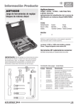
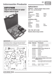
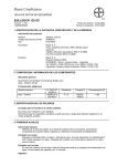
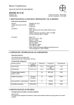
AST4845A
Petrol Engine Twin Camshaft
Setting/Locking Tool Kit
Associated Tools:
AST4844 Camshaft Sprocket Holding Tool
AST4634 Crankshaft Pulley Holding Tool
Applications:
V W GROUP 1.4/1.6 FSi and 1.4 T(F)Si
Petrol engines (CHAIN DRIVE) in
AUDI
A3
SEAT
Ibiza
SKODA
Fabia II
Superb II
AST4845A
Associated Tool:
AST4844
Associated Tool:
AST4634
Leon
Altea/XL
Roomster
Octavia II
VOLKSWAGEN
Golf
Polo
Jetta
Eos
Tiguan
Passat
Golf Plus
Scirocco
Touran
FSi engines AXU, BAG, BKG, BLF, BLN, BLP and BTS
TFSi engines BLG, BMY, BWK, CAVA, CAVB, CAVC,
CAVD, CAVE, CAVF, CAXA, CAXC, CDGA
Additional AST Tools required:
AST4844 Camshaft Sprocket Holding Tool
AST4634 Crankshaft Pulley Holding Tool
AST3054-10 DTI or other suitable Dial Gauge
IMPORTANT: Consulte siempre las instrucciones de servicio del
fabricante del vehículo, o manual de propietario, para establecer los
procedimientos y datos actuales. Información de producto Juegos de
detalle aplicaciones y el uso de las herramientas con las instrucciones
generales previstas sólo como una guía.
Kit contents/spares
Auto Service Tools
© Auto Service Tools Limited, 2010
Item
Part Number
Description
1
AST4519
2
3
4
AST4846
AST4593-1E
AST4851
TDC
Positioning Tool - use with a
suitable DTI (such as AST3054-10)
Camshaft Setting Plate
Tensioner Locking Pin
Crankshaft Locking pin
1/5
4845A.01
Estos motores VW 1.4 y 1.6 Doble árbol de levas de gasolina son de
inyección directa FSI (inyección de combustible estratificado), y son
CADENA.
El combustible se inyecta directamente en la cámara de combustión y un
sistema de carril común se utiliza con presiones de funcionamiento en
40-110 bar.
Hay varias variantes de estos motores, algunas con distribución variable
(VVT) en el árbol de levas de admisión. Versiones con turbocompresor
actualidad se han introducido (TFSi)
AST4845A FSi/TFSi Engine Setting/Locking Tool Kit
Comprises:AST4519 TDC Positioning Tool (use with suitable DTI)
AST4846 Camshaft Setting Plate
AST4593-1E Chain Tensioner Locking Pin
AST4851 Crankshaft Locking pin
IMPORTANT: Compruebe que los orificios de la parte posterior
checking valve timing
WARNING: Si bien el establecimiento de TDC en estos motores el
Retire la caja del filtro de aire, el escape de la válvula de
recirculación de gases y de la placa de la cubierta en la parte
trasera de los árboles de levas.
1
AST4519 TDC Positioning Tool (Use with suitable DTI – not included in set)
Motor / cigüeñal posición TDC correcta se establece utilizando
la herramienta AST4519 junto con un DTI adecuado (Dial
Gauge) como AST3054-10.
Retire la bujía del cilindro n º 1.
Instale el DTI para Herramienta AST4519 y asegure con el
tornillo de mariposa.
2
de los árboles de levas están colocados como se muestra en el
diagrama 2. Si no es así, girar el cigüeñal una vuelta más (360 °) y
establecer la posición PMS del cilindro n º 1, utilizando AST4519 y el
DTI.
cigüeñal no debe convertirse o se le permite moverse, más de 0,01 mm
pasó posición TDC. Si esto ocurre, apague el cigüeñal hacia atrás (en
sentido contrario a la rotación), aprox. 45 ° y luego de nuevo hacia
delante, a la posición PMS del cilindro n º 1.
3
AST4846 Camshaft Setting Plate
Inserte AST4846 Configuración de la Plata en los recreos
y los dos agujeros en la parte posterior de los árboles de
levas
NOTA: "TOP" marcado en el puente central de la placa de
calado, debe ser en la parte superior.
Si AST4846 Ajuste Plate no se puede instalar, la
sincronización del motor es incorrecta y debe ser ajustado.
Tornillo AST4519 plenamente en el orificio de la bujía del
cilindro n º 1. Girar el cigüeñal en la dirección normal de
rotación del motor de manera que el pistón reacciona sobre
el pasador indicador de AST4519 y a su vez mueve la aguja
de la DTI.
TDC se logra cuando la aguja alcanza su lectura más alta y
antes de que empiecen a moverse en la dirección inversa.
2/5
4845A.01
Auto© Service
Tools
Auto Service Tools Limited, 2010
Adjusting valve timing
Using AST4634 Crankshaft Pulley Holding Tool as a counter hold
(Associated Tool not in set), release and remove the pulley centre
bolt.
Remove the crankshaft pulley in order to remove the timing chain
cover.
Refit the pulley and bolt (ensuring correct crank gear location on the
crankshaft) to facilitate rotation of the engine.
Position the engine at TDC No.1 cylinder using AST4519 Tool and
DTI, ensuring the piston is at the top of its compression stroke, as
described earlier in “Checking valve timing”.
4
WARNING: On the rear face of the crankshaft gear is a
raised lug. This lug locates in to a recess in the crankshaft,
setting the position and providing a positive connection
between gear and crankshaft. Care must be taken when
refitting the crankshaft pulley centre bolt to ensure that the
lug on the crankshaft gear is located into the recess in the
crankshaft. Failure to do so could result in damage to the
engine.
6
AST4593-1E Tensioner Locking Pin
Turn the crankshaft against direction of engine rotation by 45° and
push the chain guide rail against the chain tensioner piston. Insert
AST4593-1E Pin to ‘lock’ the piston in position.
IMPORTANT: Mark the timing chain with direction of rotation.
7
WARNING: On engines fitted with VVT, the Camshaft Timing
Adjuster bolt (inlet camshaft sprocket) has a LEFT-HAND
THREAD.
5
Auto Service Tools
© Auto Service Tools Limited, 2010
3/5
4845A.01
WARNING: Whilst establishing TDC on these engines the
crankshaft MUST NOT be turned or be allowed to move more
than 0.01mm passed TDC position. If this occurs, turn the
crankshaft backwards (against direction of rotation), approx.
45° and then forward again, to TDC No.1 cylinder position.
8
Remove the camshaft sprockets/VVT unit, timing chain and bolts
using AST4844 Sprocket Holding Tool (Associated Tool - not in
set), as a counter hold whilst releasing the sprocket bolts. Refit the
sprockets/VVT unit with new bolts, DO NOT refit the chain at this
stage.
Tighten standard camshaft sprocket bolts to 50Nm, and VVT unit bolts
to 40Nm.
10
Oil sump removed to show crankshaft pin locking position
against crankshaft web
AST4851 Crankshaft Locking Pin
(1.4 TFSi engines only)
On 1.4 TFSi engines a Crankshaft Locking Pin is used when
adjusting the timing. This pin sets the crankshaft at TDC position by
contacting a machined face on one of the crankshaft webs with the
end of the AST4851 Pin. Fit AST4851 Crankshaft Locking Pin and
tighten to 30Nm.
Using AST4844 Sprocket Holding Tool to counter-hold the sprockets,
tighten standard camshaft sprocket bolts to 50Nm, and VVT unit bolts
to 40Nm.
9
Turn the camshafts until the AST4846 Setting Plate can be inserted in
to the recesses and the two holes in the rear of the camshafts.
NOTE: “TOP” marked on the centre bridge of the Plate, must be at
the top.
Counter-hold the sprockets using AST4844 Sprocket Holding Tool,
and slacken the camshaft sprocket/VVT unit bolts. Do not use
AST4846 Setting Plate as a counter-hold tool.
Remove one of the camshaft sprockets, install the timing chain and
refit the camshaft sprocket.
Tighten sprocket bolts finger-tight only so that the camshaft sprockets/
VVT unit can still turn freely on the camshafts.
Apply tension to the timing chain by removing the AST4593-1E Pin
from the tensioner.
WARNING: When tightening bolts the crankshaft MUST
NOT be allowed to turn and the timing chain should remain
tensioned on both sides.
For 1.4TFSi engines - Remove Crankshaft Locking Pin
AST4851.
Remove AST4846 Camshaft Setting Plate.
Turn the crankshaft two full turns in the normal direction of engine
rotation, returning to TDC position No1. cylinder using AST4519 and
DTI.
Refit AST4846 to check camshaft position. If it this is not possible,
repeat the “Timing Adjustment” procedure.
For 1.4TFSi engines - Refit AST4851 Crankshaft Locking Pin
and tighten in place to 30Nm.
Turn the crankshaft in the normal direction of engine rotation and
using AST4519 and DTI, establish TDC at No.1 cylinder.
4/5
4845A.01
Auto© Service
Tools
Auto Service Tools Limited, 2010
Remove the AST4846 Camshaft Setting Plate.
Counter-hold the camshaft sprockets using AST4844 Sprocket
Holding Tool, and tighten both sprocket bolts a further 90° ensuring
that the sprockets do not turn on the camshafts.
NOTE: When installing the rear camshaft cover, new seals will be
required.
Using AST4634 Crankshaft Pulley Holding Tool as a counter hold,
remove the old crankshaft bolt and pulley, then refit the timing chain
cover.
Refitting the crankshaft pulley/timing chain cover
Refit the crankshaft pulley using a new bolt and tighten finger-tight
(ensuring correct crankshaft gear location).
Re-check camshaft position using AST4846 and crankshaft position
using AST4519 and DTI.
IMPORTANT: A NEW crank pulley bolt MUST be fitted.
Remove Camshaft Setting Plate AST4846.
Using the AST4634 Holding Tool as a counter hold, tighten the
crankshaft bolt to the specified torque setting.
For 1.4TFSi engines - Remove AST4851 Crankshaft Locking
Pin.
A final stage timing check MUST be carried out to check the valve
timing is correct.
Turn the crankshaft two full turns in the normal direction of engine
rotation, returning to TDC No1. cylinder, using AST4519 and DTI.
Check the camshaft position by fitting AST4846 Camshaft Setting
Plate.
Remove all tools and re-assemble the vehicle
11
Later type “drilled head” bolt
Two variants of crankshaft pulley bolt have been used on these
engines. The early type is identified by having a solid bolt head, while
the later bolt has a drilling in the bolt head.
The early type (solid head) is tightened to a torque of 90Nm + 90°
The later type (drilled head) is tightened to a torque of 150Nm +
180°
Check that the crankshaft is positioned at TDC on No1. cylinder using
AST4519 and DTI.
For 1.4TFSi engines - fit the Crankshaft Locking Pin AST4851
and tighten in place to 30Nm.
WARNING: On the rear face of the crankshaft gear is a
raised lug. This lug locates in a recess in the crankshaft,
setting the position and providing a positive connection
between gear and crankshaft. Care must be taken when
refitting the crankshaft pulley centre bolt to ensure that the
lug on the crankshaft gear is located into the recess in the
crankshaft. Failure to do so could result in damage to the
engine.
Auto Service Tools Ltd, Redditch, B98 0RD, England
Tel: +44(0) 1527 528848 Fax: +44(0) 1527 517174
Email: [email protected] Website: www.asttools.co.uk
Auto Service Tools
© Auto Service Tools Limited, 2010
5/5
4845A.01