1
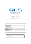
VÁLVULAS THERMO® EXPANSIÓN
SERIE “T” DESARMABLES
INSTRUCCIONES DE INSTALACIÓN Y SERVICIO
O RIFICIOS DE PURGA (BLEED HOLES) PARA LA IGUALACIÓN DE LA PRESIÓN DEL SISTEMA
Las Válvulas de Thermo® Expansión ALCO Desarmables, están diseñadas para ser utilizadas
en todo tipo de sistemas de aire condicionado, refrigeración comercial y aplicaciones en
bajas temperaturas con tangos de temperatura del evaporador de +50° a -50°F (+10° a 45°C). Las válvulas de thermo expansión de la serie “T” desarmables tienen 3 componentes:
ensamble elemento de poder, aguja y cuerpo inferior. No existen partes movibles en el
cuerpo inferior. No es necesario desoldar la línea para dar servicio a la válvula.
Las válvulas ALCO de la serie “T” desarmables se pueden suministrar con un orificio de
purga en el cuerpo inferior, lo cual permite que las presiones del sistema se igualen en el
ciclo de pare. Estas son las únicas válvulas de las que se fabrican actualmente, que
aseguran una purga adecuada en el sistema aun cuando se modifiquen o se reemplacen
los elementos de poder regulares o agujas normales.
INSTRUCCIONES
1.
2.
3.
4.
5.
6.
7.
8.
9.
10.
11.
DE
SEGURIDAD
Lea cuidadosamente las instrucciones de instalación. Si no se siguen las
instrucciones al pie de la letra, se pueden presentar fallas en la válvula, danos al
sistema o accidentes personales.
No la utilice bajo condiciones de servicio o con fluidos no especificados, sin previa
autorización del Departamento de Ingeniería y Aplicación ALCO. La utilización de
las válvulas de termo expansión en aplicaciones no especificadas, pueden ocasionar
danos personales, fallas en la válvula y/o danos al sistema.
Proteja contra vibraciones excesivas, lo cual puede causar que se rompa el tubo del
bulbo ocasionando fallas o descomposturas en la válvula.
Partículas extrañas en la válvula pueden ocasionar fallas en el diafragma, inundación
o insuficiencia. En este caso se recomienda ampliamente la utilización de un filtro
deshidratador.
Las válvulas son ajustadas en fabrica a un sobrecalentamiento especifico, si se
requiere un ajuste, consulte las instrucciones de ajuste para sobrecalentamiento
para un procedimiento adecuado. Un ajuste incorrecto puede ocasionar fallas en
la válvula y/o danos al sistema.
Asegúrese de que la válvula sea instalada con la flecha en el cuerpo de la válvula,
correspondiente a la dirección del flujo en el sistema.
En válvulas con conexiones solar, retire el elemento de poder, la aguja y los
empaques antes de aplicar la soldadura.
Utilice dos llaves de palanca para atornillar los dos cuerpos de la válvula cuidando
de no excederse en el torque para no dañar la válvula.
Es importante que la válvula sea seleccionada correctamente. Una válvula
demasiado grande puede ocasionar un control irregular. Una válvula demasiado
pequeña puede reducir considerablemente la capacidad del sistema.
No exceda la presión de seguridad de trabajo de la válvula de 450 psig (31 kg/cm2),
si se excede, la presión interna de la válvula causar danos al diafragma, ocasionando
fallas en la misma.
No exceda la temperatura de seguridad de trabajo de 250°F (120°C). Temperaturas
excesivas pueden causar danos internos, ocasionando fallas en la válvula.
INSTRUCCIONES
DE
SERVICIO
PRECAUCION: Antes de abrir cualquier sistema, asegúrese que la presión en el sistema
baje y permanezca a la presión atmosférica. El no hacerlo puede ocasionar daños al
sistema y/o personales. Para revisar, limpiar o reemplazar partes de la válvula de Termo
expansión:
1.
Desconecte la línea del igualador.
2.
Quite los tornillos.
3.
Retire cuidadosamente el elemento de poder.
4.
Remueva la aguja y los empaques.
5.
Ensamble en el mismo orden en que desensambló.
6.
Cuando vuelva a colocar el elemento de poder, asegúrese que las orejas de la aguja
coincidan con las ranuras de la cabeza de control (ver figura 2).
7.
Apriete todos los tornillos en la misma forma y aplique un torque de 300 libras por
pulgada.
8.
Revise si hay fugas.
INSTRUCCIONES
1.
2.
3.
4.
5.
6.
7.
DE I NSTALACIÓN
PRECAUCION: Antes de abrir cualquier sistema, asegúrese que la presión en el
sistema baje y permanezca a la presión atmosférica. No hacerlo puede ocasionar
danos al sistema y/o personales.
Las válvulas pueden instalarse en cualquier posición, pero deben localizarse tan
cerca como sea posible de la entrada del distribuidor o de la entrada del evaporador.
Consulte los diagramas dimensiónales.
Asegúrese de que la válvula sea instalada con la flecha en el cuerpo inferior
correspondiente a la dirección del flujo del sistema.
Instale las conexiones de línea a la válvula. En válvulas con conexiones soldar, retire
el elemento de poder, la aguja y los empaques antes de soldar. Utilice cualquier
llave de palanca en todas las partes planas de la válvula.
Cuando reensamble la válvula,
siga las instrucciones de servicio.
Figura 1
Apriete los tornillos de acuerdo
Igualador Externo
Igualador Externo
a las especificaciones de torque.
Evaporador
Evaporador
Sujete el bulbo remoto a la línea
Bulbo
Bulbo
de succión donde se la a colocar
Remoto
Remoto
el bulbo remoto, después fíjelo
Valvula
Valvula
Distribuidor
Distribuidor
Expansion
Expansion
cuidadosamente.
Termostatica
Termostatica
Correcto
Incorrecto
El bulbo remoto
El bulbo remoto
Conecte un extremo de la línea
localizado en un drene
localizado en una
correcto
trampa
del igualador externo a la
válvula. El otro extremo se Figura 2
conecta a la línea de succión
después de la localización del
bulbo remoto, conectando la
línea de tal forma que no pueda
succionar aceite de la línea de
succión. Ver figura 1.
Revise si hay fugas, suficiente
refrigerante en el sistema, y
asegúrese de que no exista gas
con efecto flash.
Ensamble de Poder
Empaque del Essamble
Ensamble de Poder
Ensamble de Aguja
Empaque del Cuerpo Inferior
8.
Empaque de Asiento
Cuerpo Inferior
Tornillos
AJUSTE
DE
SOBRECALENTAMIENTO
SELECCIÓN DEL TAMAÑO A DECUADO PARA EL ORIFICIO DE PURGA
Cuando se utiliza un motor con capacitor de arranque para accionar un compresor de
refrigeración, es necesario proporcionar ciertos mecanismos de igualación entre la alta y
la baja presión durante el ciclo de pare, de tal mofo que el motor pueda arrancar con una
torque mínimo.
Ensamble de Aguja
Ambas orejas en la aguja
deben deslizar en las
runuras del elemento
Las válvulas de termo expansión AlCO están fabricadas para un sobrecalentamiento
estático. Sin embargo, el sobrecalentamiento debe ser ajustado para cada aplicación.
Un ajuste incorrecto del sobrecalentamiento puede ocasionar mal funcionamiento en
el sistema. Para ajustar correctamente la válvula de termo expansión a otras
condiciones de sobrecalentamiento:
1.
Retire el tapón que esta a un lado de la válvula.
2.
Gire el vástago de ajuste en dirección de las manecillas del reloj para
incrementar el sobrecalentamiento, y en sentido contrario a las manecillas del
reloj para reducir el sobrecalentamiento (aproximadamente 1/2°F por cada giro,
en aplicaciones para R-22.) NOTE: Espere un tiempo razonable entre los ajustes
para que el sistema se estabilice antes de revisar el sobrecalentamiento.
3.
Cuando haya obtenido el sobrecalentamiento deseado, reinstale el tapón.
El tamaño adecuado para el orificio de purga en un sistema en particular va en función de:
los volúmenes del lado de alta y el lado de baja; la diferencia de presión a través de la
válvula al momento de pare; el tiempo necesario para igualar presiones y la cantidad de
carga de refrigerante. Debido a las múltiples variantes, debe probarse cada aplicación
para determinar el tamaño del orificio de purga aumenta el área total efectiva del puerto
de la válvula de termo expansión y puede afectar la elección del tamaño de la aguja.
TCL(E) D
escr
n de Dime
nsi
one
De
criipc
pciión
Dimensi
nsione
oness
Figura 3
B
C
1-25/32
3-45/64
3/8x5/8SAE
1/2x1/2SAE
2-5/32
1-13/32
DIRECCION DE FLUJO
1-5/8
1-5/8
5/8x5/8ODF
5/8x7/8ODF 3-45/64 1-19/32 1-15/16
**Medida de Orificio de Purga estampado en el Cuerpo
Tabla 1 - SSali
ali
da Sim
ple Se
T” C
ue
es ccon
on O
ga
alid
Simp
Serries ““T”
Cue
uerr po
poss In
Infferior
ore
Orrifi
ficcio de Pur
Purg
5/8x1-1/8ODF
M o d e l o d e Va l v u l a
7/8x1-1/8ODF 3-13/16 1-15/16
C a p a c i d a d d e l B y p a s s % S e g u n e l D i a m e t r o d e O r i f i c i o d e Pu r g a
F
11/ 16
3/ 8
43/ 64
23/ 64
1-9/16 1-13/64 11/16
1/2x5/8ODF 3-11/16
DIRECCION DE FLUJO
E
G
Ent.
Sal i da
3/ 8
5/ 16
1-37/64
3-11/16
3/8x5/8ODF
1/2x1/2ODF 3-45/64
PRECAUCIÓN ORIFICIO DE PURGA EN EL CUERPO
D
Pr o f . C o n e x.
1-63/64
1-31/32 1-9/16
3/8x1/2ODF
LOCALIZACION DE
ORIFICIO DE PURGA
LOCALIZACION DE
ORIFICIO DE PURGA
A
3/8x1/2SAE
La tabla 1 se debe utilizar como una guía en la elección de tamaños de los orificios de
purga, pero la elección final no debe hacerse sin una prueba retallada.
La letra “B” se utiliza después del numero de serie de las válvulas para indicar una válvula
con orificio purga. Por ejemplo: TCLBFW. El cuerpo inferior esta marcado (ver la figura 3)
con la letra “B” seguida del diámetro del orificio de purga, ejemplo: B036 y cada cuerpo
inferior tiene una pequeña etiqueta sensible a la presión. Esta etiqueta se muestra
enseguida.
TCLE
T i p o Rec t o
D i m en s i o n es
C o n exi o n es
Es tandar 1
1/ 2
2-9/16
DIA.
3/ 8
43/ 64
23/ 64
11/ 16
3/ 8
3/ 8
3/ 8
Conexion Recta
1/ 2
1/ 2
2-3/8
3/ 4
Conexion en Angulo
3/ 4
29/ 32
T ipo Angulo
R4 0 4 A /
R5 0 7
R1 3 4 a
R4 0 7 C
R1 2
R2 2
10%
R5 0 2
15%
20%
25%
30%
40%
3/8x1/2SAE
D IA . ME D . D IA . ME D . D IA . ME D . D IA . ME D . D IA . ME D . D IA . ME D .
P U LG . B R O C A P U LG . B R O C A P U LG . B R O C A P U LG . B R O C A P U LG . B R O C A P U LG . B R O C A
4-9/64
3/8x5/8SAE
1/2x5/8SAE
4-25/64
TCL1/4M
TCL1/4R/P
TCL1/2N
TCL1/4F
TCL1/2H
TCL1/4R
--
--
--
--
--
--
--
--
--
--
--
--
TCL3/4M
TCL1/2R/P
TCL1N
TCL1/2F
TCL1H
TCL1/2R
.018
77
.021
75
.024
73
.026
71
.0292
69
.035
65
TCL1/12M
TCL1R/P
TCL2N
TCL1F
TCL2H
TCL1R
.026
71
.0312
1/ 32
.036
64
.040
60
.0465
56
.052
55
3/8x5/8ODF
TCL21/2M
TCL2R/P
TCL3N
TCL2F
TCL3H
TCL2R
.028
70
.035
65
.040
60
.043
57
.0468
3/ 64
.055
54
1/2x5/8ODF 4-13/64
TCL31/2M
TCL3R/P
TCL5N
TCL3F
TCL51/2M TCL41/2R/P TCL71/2N
TCL71/2M
TCL9M
TCL7R/P
TCL8R/P
TCL4F
TCL10N
TCL5H
.035
TCL71/2H TCL41/2R
TCL61/2F
TCL12N
TCL3R
TCL10H
TCL71/2F
TCL7R
TCL12H
TCL8
65
.043
57
.052
55
.055
54
.0625
1/ 16
.070
.043
57
.052
55
.0595
53
.067
51
.076
48
.086
44
55
.0595
53
.070
50
.0785
47
.086
44
.0995
39
.052
55
.0595
53
.070
50
.0785
47
.086
44
.0995
1-1/2
3-3/16
1-5/8
3/8x1/2ODF
3-5/32 1-19/32
5/8x7/8ODF
4-53/64 3-9/16
7/8x1-1/8ODM
2
39
A
B
5-25/64
2
Com
pone
ntes In
ompone
ponen
Inttercamb
rcambiiable
less
ODF :ODM
7/8:1-1/8
ODF :ODM
7/8:1-1/8
5-1/2
3-3/8
R4 0 4 A /
R5 0 7
R1 3 4 a
R4 0 7 C
R1 2
R2 2
R5 0 2
se
se
Pa r t e N o .
es p ec i f i q u e
TCL(E)1/2N TCL(E)1/4F
TCL(E)1/2H
TCL(E)3/4M
TCL(E)1/2R/P
TCL(E)1N
TCL(E)1/2F
TCL(E)1H
TCL(E)1/12M
TCL(E)1R/P
TCL(E)2N
TCL(E)1F
TCL(E)2H
TCl(E)21/2M
TCL(E)2R/P
TCL(E)3N
TCL(E)2F
TCL(E)3H
Pa r t e N o .
TCL(E)3R/P
TCL(E)5N
TCL(E)3F
TCL(E)3R
X22440-B5*
2
C
D
ODF :ODM
7/8:1-1/8
ODF :ODM
7/8:1-1/8
5-29/64
2
1-25/32
3
ODF :ODM
7/8:1-1/8
6
3-3/8
2
R5 0 2
Pa r t e N o .
R1 2
R2 2
R5 0 2
Pa r t e N o .
TCLE25F
TCLE50H
TCLE25R
XC709-B7
TCL(E)1/4F
TCL(E)1/2H
TCL(E)1/4R
X22440-B1*
TCLE50F
TCLE100H
TCLE50R
X C 709B000*
TCL(E)1/2F
TCL(E)1H
TCL(E)1/2R
X22440-B2*
TCL(E)1F
TCL(E)2H
TCL(E)1R
Entr ada
ODM:1-1/8
--
6-3/16
H
J(D i a .)
3/ 4
2-7/8
3/ 4
2-7/8
TER, TIR, THR
1-1/8
E
F
19/32 2-17/64
G
H
J(D i a .)
1-1/8
3/ 4
2-7/8
3/ 4
1-1/8
3/ 4
2-7/8
Conexion en Angulo
Conexion Recta
Sal i da
A
ODM:1-1/8 5-29/64
B
C
D
2
1-25/32
3
E
F
G
H
J(D i a .)
--
--
2-7/8
1-1/8
--
2-7/8
19/32 2-17/64
T ipo Angulo T HR
ODM:1-1/8
6
ODM:1-1/8
3-3/8
2
4-5/32 2-13/16
--
TER
R, THR Dime
nsi
one
TER,, TI
TIR
Dimensi
nsione
oness de Bulbo
Lar go de
Tu b o
Capilar
B u l b o Rem o t o
Es tandar
Dia.
Lar go*
10'
1 5 ' or 2 0 '
TJLE
B u l b o d e Res p u es t a
Ra pi da 2
5'
Dia.
Lar go*
3/ 8
2-1/16
--
--
4-7/8
3/ 4
4 0 ' or 5 0 '
6-3/16
Va l v u l a T J L E 1
Conexion Recta
TCLE300H
TCLE200R
XC709-B0*
TCL(E)2F
TCL(E)3H
TCL(E)2R
X22440-B4*
TCLE250F
TCLE400H
TCLE250R
XC709-B6*
TCL(E)3F
TCL(E)5H
TCL(E)3R
X22440-B5*
TCLE300F
TCLE500H
TCLE300R
XC709-B1*
TCL(E)3F
TCL(E)5H
TCL(E)3R
X22440-B5*
TCLE400F
TCLE700H
TCLE450R
XC709-B4*
TCL(E)4F
TCLE600F
TCLE900H
TCLE650R
XC709-B2*
TCL(E)6-1/2F
TCL(E)10H
TCL(E)7R
X22440-B7*
TCLE650F
TCLE1000H
TCLE700R
XC709-B3*
TCL(E)6-1/2F
TCL(E)10H
TCL(E)7R
X22440-B7*
Entr ada
Sal i da
5/ 8
1-1/8
A
B
C
1-5/8
7/ 8
1-1/8
7/ 8
1-3/8
4-55/64
ODF :ODM
5/8:7/8
ODF :ODM
7/8:1-1/8
1-15/16
D
2-1/2
TCLE750F
TCLE1200H
TCLE800R
XC709-B5*
TCL(E)7-1/2F
TCL(E)12H
TCL(E)8R
X22440-B8*
E
F
G
17/ 32
1-11/32 1-23/32 45/64
3/ 4
2-11/16
H
J
29/ 32
--
31/ 32
5-1/32 3-15/32
2
1-11/32 1-27/32 13/16
1-1/16
1
1-1/8
TJR
T i p o Rec t o T JR
D i m en s i o n es
Entr ada
Sal i da
A
B
ODF :ODM
7/8:1-1/8
ODF :ODM
7/8:1-1/8
5-23/64
2
ODF :ODM
7/8:1-1/8
ODF :ODM
7/8:1-1/8
5-1/2
3-3/8
C
D
E
F
G
H
J
3/ 4
3/ 4
1-1/8
1-1/8
3/ 4
1-1/8
1-25/32 2-15/16 19/32 2-13/64
T i po A n gu l o T JR
2
3-21/32 2-5/16
3/ 4
TJLE
nsi
one
TJLE,, TJR Dime
Dimensi
nsione
oness de Bulbo
Lar go de
Tu b o
Capilar
X22440-B6*
*Agregue el código del igualador con letra “A” para interno o “B” para externo para dar el numero de parte completo de la aguja. NOTA: Elimine la letra “E” del tipo de la válvula para
identificar une válvula con igualador interno.
Conexion en Angulo
D i m en s i o n es
T i po A n gu l o T JLE
X22440-B3*
TCLE200F
TCL(E)7-1/2H TCL(E)4-1/2R
3/ 4
D i m en s i o n es
Va l v u l a T J R 1
XC709-B00*
3/ 4
4-5/32 2-13/16
Va l v u l a T H R 1
Ens amble de
Aguja
R2 2
TCLE100R
G
T i p o Rec t o T JLE
R1 2
TCLE200H
6-1/16
4 0 ' or 5 0 '
--
4-13/16
TJLE
escr
n de Dime
nsi
one
TJLE,, TJR D
De
criipc
pcii ón
Dimensi
nsione
oness
N o m en c l a t u r a N u ev a
M o d e l o d e Va l v u l a
F
T i p o Rec t o T HR
Las agujas nuevas son intercambiables con las anteriores versiones. Para modernizar nuestro producto, se han hecho modificaciones menores en la construcción de las agujas. Las
nuevas construcciones están identificadas por un nuevo numero de parte de aguja y por un nuevo numero de tipo de válvula.
Ens amble de
Aguja
1
1-3/16
D i m en s i o n es
B
Noe
mclatur
a An
s. Nue
va
oem
tura
Antter ior vvs.
Nuev
TCLE100F
E
30'
M o d e l o d e Va l v u l a
30'
3/ 8
Bulbo de respuesta rápida disponsible unicamente con tubo capilar de 5’ ó 10’.
*Pulgadas
3-21/32 2-5/16
A
*Agregue “A” para igualador interno o “B” para externo.
**Agregue: Carga de refrigerante FC=R12; HC=R22; RC=R502; etc. Aumente la longitud del tubo capilar’ – 1=5’ (1.50 mts); 2=10’ (3.00 mts); 3=15’ (4.50 mts); etc.
NOTA: No utilice una aguja para usarse en un elemento con igualador externo, con un elemento de poder para igualador interno o viceversa.
N o m en c l a t u r a A n t er i o r
1 5 ' or 2 0 '
3-9/16
Lar go*
T ipo Angulo T IR
3/8x1/2 ODF
3/8x5/8 ODF 3/8x1/2 ODF XB-1019-**
TCL(E)1/2R X22440-B2*
3/8x5/8 1/2x1/2 ODF
(Bulbo
1/2x5/8 ODF 1/2x5/8 ODF Estandar )
TCL(E)1R X22440-B3*
5/8x7/8 ODF
TCL(E)2R X22440-B4*
5/8x5/8 ODF
TCL(E)5H
5/ 8
Dia.
2
D
Sal i da
1/4x3/8 ODF
5/8x1-1/8 ODF 5/8x7/8 ODF
1/2x5/8 7/8x1-1/8 ODF
XB-8019-**
TCL(E)51/2M TCL(E)41/2R/P TCL(E)71/2N TCL(E)4F TCL(E)71/2H TCL(E)41/2R X22440-B6*
3/8x1/2 SAE 3/8x1/2 SAE (Bulbo de
3/8x5/8 SAE 3/8x5/8 SAE Respuesta
TCL(E)71/2M TCL(E)7R/P
TCL(E)10N TCL(E)61/2F TCL(E)10H
TCL(E)7R X22440-B7*
Rapida)
5/8x7/8 1/2x1/2 SAE
TCL(E)9M
TCL(E)8R/P
TCL(E)12N TCL(E)71/2F TCL(E)12H
TCL(E)8R X22440-B8*
1/2x5/8 SAE 1/2x5/8 SAE
TCL(E)31/2M
C
Entr ada
ODF :ODM
7/8:1-1/8
TCL(E)1/4R X22440-B1*
1-1/16
3-1/16
10'
13/ 16
1-25/32 2-15/16 19/32 2-13/64 1-1/8
Va l v u l a T I R 1
o r d en
TCL(E)1/4R/P
11/ 16
1/ 16
Lar go*
T i p o Rec t o T I R
en s u
TCL(E)1/4M
1-3/16
Dia.
5'
B u l b o d e Res p u es t a
Ra pi da 2
T ipo Angulo T ER
Ens amble
E l em en t o
d e Po d e r
T ipo
Angulo
T i p o Rec t o
9/ 16
9/ 16
--
B u l b o Rem o t o
Es tandar
Lar go de
Tu b o
Capilar
D i m en s i o n es
Sal i da
m en o s q u e
1-1/16
1-11/32 1-11/16 13/16
Va l v u l a T E R 1
ODF :ODM
7/8:1-1/8
Es tandar a
2-9/16
DIA.
T i p o Rec t o T E R
Entr ada
Ens amble
de Aguja
7/ 16
TER
R, THR D
escr
n de Dime
nsi
one
TER,, TI
TIR
De
criipc
pciión
Dimensi
nsione
oness
ODF :ODM
7/8:1-1/8
C o n exi o n es E s t a n d a r
--
--
1-3/8
3-1/32 1-15/32
4-7/64
Los tamaños de orificios de purga mostrados están basados en un porcentaje de área total efectiva del puerto de la válvula. Esto no indica necesariamente el porcentaje de la
capacidad de la válvula que será desviada (bypass). Los tamaños de orificios antes mencionados deben utilizarse solo como referencia. La siguiente tolerancia aplica para los
diámetros de orificios de purga: .0135 to .060 dia. = +.002 to -.001; .061 to .115 dia. = +.003 to -.0015.
M e d i d a s d e Va l v u l a s
TCL(E) Dime
nsi
one
Dimensi
nsione
oness de Bulbo
1-1/8
1/4x3/8ODF 3-61/64 2-29/32 1-11/32 1-13/64 15/16
50
.052
3-1/16
B u l b o Rem o t o
Es tandar
Dia.
Lar go*
5'
3-1/16
10'
3-9/16
1 5 ' or 2 0 '
5/ 8
30'
4 0 ' or 5 0 '
Dia.
Lar go*
3/ 8
1-3/16
--
--
Conexion Recta
Conexion en Angulo
4-13/16
6-1/16
3/ 4
B u l b o d e Res p u es t a
Ra pi da 2
6-3/16
Las conexiones de la descripción son medidas estándar. Para medidas no estándar
consulte a Alco.
En diámetro arriba de 2 1/8” hay necesidad de cambiar el ensamble de poder.
1
Alco Controls Division - Emerson Climate Technologies
St. Louis, MO 63141
PA-00152S
12/02
TAKE–A–PART SERIES
THERMO® EXPANSION VALVES
INSTALLATION & SERVICE INSTRUCTIONS
ALCO Take-A-Part Thermo® Expansion Valves are designed for use on all types of air conditioning, commercial refrigeration and low temperature applications with evaporator temperature ranges of + 50°F to – 50°F. Take-A-Part T-series thermo expansion valves have 3
component parts: power assembly, cage assembly and flange. There are no working parts in
the flange. It is never necessary to break the line connections to service the valve.
SAFETY INSTRUCTIONS
1.
Read Installation Instructions thoroughly. Failure to follow instructions may result in
valve failure, system damage or personal injury
injury.
2. Do not use on service conditions or fluids not specifically cataloged without prior
approval of ALCO Applications Engineering Department. Use of Thermo valves on
applications not specifically cataloged can result in personal injury, valve failure and/
or system damage.
3. Protect against excessive vibration, which may cause the bulb tube to break, resulting
in valve failure or malfunction.
4. Foreign matter in the Thermo valve may cause diaphragm failure, flooding, or
starving. Use of an ALCO liquid line filter-drier is strongly recommended.
5. Valves are factory-set to a specific superheat. If adjustment is needed, refer to
superheat adjustment instructions for proper procedure. Improper adjustment may
result in valve malfunction and/or system damage.
6. Be sure the valve is installed with the flow arrow on the valve body corresponding to
the flow direction through the system piping.
7. On valves with solder connections, remove the power assembly, cage assembly and
gaskets prior to brazing.
8. Use back-up wrench on all wrench flats. Over-torquing may result in
valve body damage.
9. Proper valve sizing is important. An oversized valve may result in erratic control. An
undersized valve may
M a x i m u m D e h y d r a t i o n Te m p e r a t u r e ° F
considerably
reduce
system capacity.
T h er m o s t a t i c C h a r g e
R
e
f r i g er a n t
10. Do not exceed the
CA, C
Z
W MO P
valve’smaximum
R12/R134a
190
250
250
working pressure of
R22
160
185
250
450 psig-if exceeded,
internal valve pressure R502, R404A,
150
170
250
R507
could cause damage to
the diaphragm, resulting This table refers to the maximum dehydration temperatures when the
bulb and valve body are subjec ted to the same temperature. On L, C,
in valve malfunction.
and Z c harges, 250°F maximum valve body temperature is permissible
11. Do not exceed maximum if the bulb temperature does not exceed those shown.
working temperature.
Excess temperatures could causeinternal damage, resulting in valve malfunction.
BLEED HOLES FOR SYSTEM PRESSURE EQUALIZATION
INSTALLATION INSTRUCTIONS
1.
2.
3.
4.
5.
6.
7.
8.
WARNING
WARNING: Before opening any system, make sure the pressure in the system is
brought to and remains at atmospheric pressure. Failure to comply may result in
system damage and/or personal injury
injury.
Valves may be installed in any position, but should be located as close as possible to the
distributor or evaporator inlet. Refer to dimensional diagrams for valve roughing-in
dimensions.
Be sure valve is installed with its flow arrow corresponding to the flowdirection thru the
piping.
Install line connections to valve. On valves with solder connections, remove the power
assembly, cage assembly and gaskets prior to brazing. Use back-up wrench on all
wrench flats.
When reassembling the valve, follow the service instructions.
Figure 1
Tighten cap screws to torque specification.
Attach the remote bulb to the suction line as close to the evaporator
as possible. Position the bulb at the
4 or 8 o’clock position. Clean the
surface of the suction line where
the remote bulb is to be attached,
Figure 2
then securely fasten the bulb.
Connect one end of the external
equalizer line to the valve. Connect
the other end to the suction line,
slightly downstream from the remote bulb location, and positioned
so that it cannot siphon oil from the
suction line. See figure 1.
Check for leaks, sufficient system
refrigerant, and be sure no flash
gas is present.
SUPERHEAT ADJUSTMENT
ALCO Thermo Valves are factory-set for a static superheat.
However, the superheat should be adjusted for the application. Improper
superheat adjustment may result in system malfunction. To properly adjust
Thermo valve to other superheat settings:
1. Remove seal cap on side of valve.
2. Turn the adjusting stem in a clockwise direction to increase the super
heat, and counterclockwise to decrease superheat (approximately 1/2°F
per turn, R22 applications).
NOTE: Allow adequate time between adjustments for system to stabilize
before checking superheat.
3. When the desired superheat setting is achieved, reinstall the seal cap.
The required bleed hole size for a particular system is a function of: the high side and low
side volumes; the pressure difference across the valve at the time of shut-down; the equalization time required and the quantity of refrigerant charge. Due to the many variables, each
application must be tested to determine the correct size required. It should be remembered
that bleed hole size adds to the total effective port area of the Thermo valve and may affect
cage size selection.
Table 1 should be used as a guide in selecting bleed hole sizes, but the final selection
should not be made wthout thorough testing.
TCL(E) R
oughin
g-In Dime
nsi
ons
Ro
ghing
Dimensi
nsions
D i m en s i o n s
A
B
3/8x1/2SAE
C
1-25/32
3-45/64
3/8x5/8SAE
1/2x1/2SAE
Figure 3
D
3/8x1/2ODF
2-5/32
1-13/32
1-5/8
1-5/8
5/8x5/8ODF
5/8x7/8ODF 3-45/64 1-19/32 1-15/16
R1 3 4 a
R4 0 4 A /
R5 0 7
R4 0 7 C
R1 2
R2 2
5/8x1-1/8ODF
10%
R5 0 2
DIA.
IN.
15%
DRILL
SIZE
DIA.
IN.
20%
DRILL
SIZE
DIA.
IN.
25%
DRILL
SIZE
DIA.
IN.
DIA.
IN.
40%
DRILL
SIZE
DIA.
IN.
3/8x1/2SAE
DRILL
SIZE
4-9/64
3/8x5/8SAE
1/2x5/8SAE
4-25/64
TCL1/4M
TCL1/4R/P
TCL1/2N
TCL1/4F
TCL1/2H
TCL1/4R
--
--
--
--
--
--
--
--
--
--
--
--
TCL1/2R/P
TCL1N
TCL1/2F
TCL1H
TCL1/2R
.018
77
.021
75
.024
73
.026
71
.0292
69
.035
65
TCL1/12M
TCL1R/P
TCL2N
TCL1F
TCL2H
TCL1R
.026
71
.0312
1/ 32
.036
64
.040
60
.0465
56
.052
55
3/8x5/8ODF
TCL21/2M
TCL2R/P
TCL3N
TCL2F
TCL3H
TCL2R
.028
70
.035
65
.040
60
.043
57
.0468
3/ 64
.055
54
1/2x5/8ODF 4-13/64
TCL3R/P
TCL5N
TCL3F
TCL51/2M TCL41/2R/P TCL71/2N
TCL4F
TCL5H
TCL3R
.035
TCL71/2H TCL41/2R
65
.043
57
.052
55
.055
54
.0625
1/ 16
.070
.043
57
.052
55
.0595
53
.067
51
.076
48
.086
44
TCL7R/P
TCL10N
TCL61/2F
TCL10H
TCL7R
.052
55
.0595
53
.070
50
.0785
47
.086
44
.0995
39
TCL9M
TCL8R/P
TCL12N
TCL71/2F
TCL12H
TCL8
.052
55
.0595
53
.070
50
.0785
47
.086
44
.0995
39
*Bleed hole sizes shown above are on a percent of full effective port area of valve. This does not necessarily indicate the percent of valve capacity that will be bypassed. The hole sizes
shown above should be used for reference only. The following tolerance applies to the bleed hole diameters: .0135 to .060 dia. = +.002 to -.001; .061 to .115 dia. = +.003 to -.0015.
In
han
ge
able C
om
pone
nts
Intterc
rch
ange
gea
Com
ompone
ponen
R4 0 4 A /
R5 0 7
R1 3 4 a
R4 0 7 C
R1 2
TCL(E)1/4M TCL(E)1/4R/P TCL(E)1/2N TCL(E)1/4F
R2 2
R5 0 2
St a n d a r d C o n n ec t i o n s
Cage
A s s em b l y
Pa r t
N u m b er
St andar d
U n l es s
Sp ec i f i ed
o n O r d er
S/ T St y l e
Cage
A s s em b l y
Pa r t
A n g l e St y l e N u m b er
TCL(E)1/2H TCL(E)1/4R X22440-B1*
TCL(E)3/4M TCL(E)1/2R/P
TCL(E)1N
TCL(E)1/2F
TCL(E)1H
TCL(E)1/12M
TCL(E)1R/P
TCL(E)2N
TCL(E)1F
TCL(E)2H
TCl(E)21/2M
TCL(E)2R/P
TCL(E)3N
TCL(E)2F
TCL(E)3H
1/4x3/8 ODF
3/8x1/2 ODF
3/8x5/8 ODF 3/8x1/2 ODF XB-1019-**
TCL(E)1/2R X22440-B2*
3/8x5/8 1/2x1/2 ODF
(Standard
1/2x5/8 ODF 1/2x5/8 ODF
Bulb)
TCL(E)1R X22440-B3*
5/8x7/8 ODF
TCL(E)2R X22440-B4*
5/8x5/8 ODF
5/8x1-1/8 ODF 5/8x7/8 ODF
1/2x5/8 7/8x1-1/8 ODF
XB-8019-**
TCL(E)51/2M TCL(E)41/2R/P TCL(E)71/2N TCL(E)4F TCL(E)71/2H TCL(E)41/2R X22440-B6*
3/8x1/2 SAE 3/8x1/2 SAE
(Rapid
3/8x5/8 SAE 3/8x5/8 SAE Response
TCL(E)71/2M TCL(E)7R/P
TCL(E)10N TCL(E)61/2F TCL(E)10H
TCL(E)7R X22440-B7*
Bulb)
5/8x7/8 1/2x1/2 SAE
TCL(E)9M
TCL(E)8R/P
TCL(E)12N TCL(E)71/2F TCL(E)12H
TCL(E)8R X22440-B8*
1/2x5/8 SAE 1/2x5/8 SAE
TCL(E)31/2M
TCL(E)3R/P
TCL(E)5N
TCL(E)3F
TCL(E)5H
TCL(E)3R
X22440-B5*
3/8x1/2ODF
R1 2
TCLE25F
TCLE50F
TCLE50H
TCLE100H
R5 0 2
TCLE25R
TCLE50R
Va l v e T y p e
XC709-B7
X C 709B000*
R1 2
TCL(E)1/4F
TCL(E)1/2F
3-3/16
1-5/8
R2 2
TCL(E)1/2H
TCL(E)1H
R5 0 2
TCL(E)1/4R
TCL(E)1/2R
Cage
A s s em b l y
Pa r t N o .
X22440-B1*
X22440-B2*
XC709-B00*
TCL(E)1F
TCL(E)2H
TCL(E)1R
X22440-B3*
TCLE200F
TCLE300H
TCLE200R
XC709-B0*
TCL(E)2F
TCL(E)3H
TCL(E)2R
X22440-B4*
TCLE250F
TCLE400H
TCLE250R
XC709-B6*
TCL(E)3F
TCL(E)5H
TCL(E)3R
TCLE300F
TCLE500H
TCLE300R
XC709-B1*
TCL(E)3F
TCL(E)5H
TCL(E)3R
TCLE700H
TCLE450R
XC709-B4*
TCL(E)4F
TCLE600F
TCLE900H
TCLE650R
XC709-B2*
TCL(E)6-1/2F
TCLE1000H
TCLE1200H
TCLE700R
TCLE800R
XC709-B3*
XC709-B5*
TCL(E)6-1/2F
TCL(E)7-1/2F
*Add “A” for internal or “B” for external equalizer to make cage assembly part number complete..
Note: Delete the letter “E” from valve type for internally equalized valve.
11/ 16
3/ 8
TCL(E)7-1/2H TCL(E)4-1/2R
TCL(E)10H
TCL(E)10H
TCL(E)12H
TCL(E)7R
TCL(E)7R
TCL(E)8R
3/ 8
1/ 2
ANGLE
STRAIGHT-THRU
1/ 2
3/ 4
29/ 32
2
1-1/16
9/ 16
1-3/16
11/ 16
9/ 16
--
2-9/16
DIA.
Dia.
5'
1/ 16
1 5 ' or 2 0 '
5/ 8
30'
1
Ra p i d Res p o n s e
Bulb2
Len g t h
3-1/16
10'
13/ 16
1-1/16
St a n d a r d Rem o t e
Bulb
3-9/16
3/ 4
Dia.
Len g t h
3/ 8
1-3/16
--
--
4-13/16
6-1/16
4 0 ' or 5 0 '
6-3/16
Rapid Response bulb available only with 5’ or 10’ capillary tubing and “G” (gas) charge.
2
T E R S t r a i g h t-T h r u S t y l e
TER, TIR, THR
D i m en s i o n s
I n l et
O u t l et
A
B
ODF :ODM
7/8:1-1/8
ODF :ODM
7/8:1-1/8
5-25/64
2
C
D
E
F
G
1-25/32 2-15/16 19/32 2-13/64 1-1/8
H
J(D i a .)
3/ 4
2-7/8
3/ 4
2-7/8
T ER A ngl e St y l e
ODF :ODM
7/8:1-1/8
ODF :ODM
7/8:1-1/8
5-1/2
3-3/8
2
3-21/32 2-5/16
3/ 4
1-1/8
F
G
T I R S t r a i g h t-T h r u S t y l e
T I R Va l v e 1
D i m en s i o n s
I n l et
O u t l et
A
B
C
D
ODF :ODM
7/8:1-1/8
ODF :ODM
7/8:1-1/8
5-29/64
2
1-25/32
3
E
19/32 2-17/64 1-1/8
H
J(D i a .)
3/ 4
2-7/8
T IR A ngl e St y l e
ODF :ODM
7/8:1-1/8
ODF :ODM
7/8:1-1/8
6
3-3/8
2
4-5/32 2-13/16
3/ 4
1-1/8
3/ 4
2-7/8
F
G
H
J(D i a .)
--
--
2-7/8
1-1/8
--
2-7/8
STRAIGHT-THRU
ANGLE
T H R S t r a i g h t-T h r u S t y l e
T H R Va l v e 1
I n l et
D i m en s i o n s
O u t l et
ODM:1-1/8
A
ODM:1-1/8 5-29/64
B
C
D
2
1-25/32
3
E
19/32 2-17/64
T HR A ngl e St y l e
ODM:1-1/8
6
ODM:1-1/8
3-3/8
2
4-5/32 2-13/16
--
TJLE
TER
R, THR R
emote Bulb Dime
nsi
ons
TER,, TI
TIR
Re
Dimensi
nsions
St a n d a r d Rem o t e
Bulb
Capillar y
Tu b i n g
Len g t h
Dia.
1 5 ' or 2 0 '
Ra p i d Res p o n s e
Bulb2
Len g t h
Dia.
Len g t h
3/ 8
2-1/16
--
--
4-7/8
3/ 4
30'
6-3/16
ANGLE
STRAIGHT-THRU
TJLE
oughin
g-In Dime
nsi
ons
TJLE,, TJR R
Ro
ghing
Dimensi
nsions
T J L E S t r a i g h t-T h r u S t y l e
T J L E Va l v e 1
D i m en s i o n s
I n l et
O u t l et
5/ 8
1-1/8
A
B
C
1-5/8
7/ 8
1-1/8
7/ 8
1-3/8
ODF :ODM
5/8:7/8
ODF :ODM
7/8:1-1/8
4-55/64
1-15/16
D
2-1/2
E
F
G
17/ 32
1-11/32 1-23/32 45/64
2-11/16
3/ 4
H
29/ 32
J
--
31/ 32
TJR
T JLE A n gl e St y l e
5-1/32 3-15/32
2
1-11/32 1-27/32 13/16
1-1/16
1
1-1/8
T J R S t r a i g h t-T h r u S t y l e
T J R Va l v e 1
D i m en s i o n s
B
X22440-B5*
ODF :ODM
7/8:1-1/8
ODF :ODM
7/8:1-1/8
5-23/64
2
X22440-B5*
ODF :ODM
7/8:1-1/8
ODF :ODM
7/8:1-1/8
5-1/2
3-3/8
X22440-B8*
7/ 16
1-11/32 1-11/16 13/16
T E R Va l v e 1
A
X22440-B7*
Capillar y
Tu b i n g
Len g t h
TER
R, THR R
oughin
g-In Dime
nsi
ons
TER,, TI
TIR
Ro
ghing
Dimensi
nsions
O u t l et
X22440-B7*
--
--
1-3/8
3-5/32 1-19/32
I n l et
X22440-B6*
TCL(E) R
emote Bulb Dime
nsi
ons
Re
Dimensi
nsions
1-1/8
4 0 ' or 5 0 '
TCLE100R
TCLE400F
23/ 64
3/ 8
Connections shown are standard sizes. Consult Alco for non-standard sizes.
Note: Allow 2-1/8” above valve for removal of power assembly.
N ew St y l e
TCLE200H
TCLE750F
1-1/2
10'
R2 2
3/ 8
1/ 2
2-9/16
DIA.
3/ 8
43/ 64
5'
TCLE100F
TCLE650F
3-1/16
5/8x7/8ODF
4-53/64 3-9/16
7/8x1-1/8ODM
New cage assemblies are interchangeable with the old versions. To modernize our product, minor changes have been amde in the construction of cage assemblies. The new
constructions have been identified by a new cage assembly part number and a new valve type number.
Cage
A s s em b l y
Pa r t N o .
23/ 64
3/ 4
3-1/32 1-15/32
4-7/64
Old vve
er su
ew N
ome
nc
e
suss N
Ne
Nome
omenc
ncllatur
ture
Va l v e T y p e
43/ 64
5/ 16
1
*Add “A” for internal or “B” for external equalizer.
**Add Refrigerant Charge: M=R134a; S=R404A; P=R507; N=R407C; F=R12; H=R22; R=R502
Note: Do not use an externally equalized cage assembly with an internally equalized power assembly or vice versa.
O l d St y l e
3/ 8
1/4x3/8ODF 3-61/64 2-29/32 1-11/32 1-13/64 15/16
50
TCL71/2M
Va l v e T y p e N u m b e r
11/ 16
I n l et O u t l et
S t r a i g h t-T h r u S t y l e
TCL3/4M
TCL31/2M
G
2-3/8
7/8x1-1/8ODF 3-13/16 1-15/16
30%
DRILL
SIZE
F
1-9/16 1-13/64 11/16
1/2x5/8ODF 3-11/16
B l eed Ho l e D i a m et er f o r % C a p a c i t y B y p a s s
E
1-37/64
3-11/16
1/2x1/2ODF 3-45/64
Table 1 - Sin
gle O
utle
T” Se
od
y Fl
an
ge
ole
Single
Ou
tlett ““T”
Serries B
Bod
ody
Flan
ange
gess with Bleed H
Hole
So c k et D ep t h
1-63/64
1-31/32 1-9/16
3/8x5/8ODF
Va l v e T y p e N u m b e r
TCLE
S t r a i g h t-T h r u S t y l e
St andar d
C o n n ec t i o n s 1
Warning
Bleed Hole
In Flange
SERVICE INSTRUCTIONS
WARNING
WARNING: Before opening any system, make sure the pressure in the system is brought to
and remains at atmospheric pressure. Failure to comply may result in system damage and/
or personal injury.
To inspect, clean, or replace parts of the Thermo valve:
1. Disconnect equalizer line.
2. Remove the cap screws.
3. Carefully lift off the power assembly.
4. Remove cage assembly and gaskets.
5. Lightly oil gasket with refrigeration oil.
NOTE: Good service practice requires replacing all gaskets whenever a valve is opened.
6. Assemble in the same order as disassembled.
7. When putting the power assembly on, make sure the cage assembly lugs line up with
the slots inside the power assembly (see figure 2).
8. Tighten cap screws evenly and torque to 300 inch pounds.
9. Check for leaks.
SELECTING PROPER BLEED HOLE SIZE
When a permanent split-capacitor motor is used to drive a refrigeration compressor, it
is necessary to provide some means of equalizing the high and low side pressures during the
“off”cycle so that the motor can start with minimum torque.
ALCO “T” Series valves, with take-a-part construction, can be furnished with a bleed
hole in the body flange, which allows system pressures to equalize on the “off” cycle. These
are the only valves presently manufactured that insure proper bleed in the system even
though standard power assemblies or standard cage assemblies are changed or replaced.
The letter“B” is used after the valve series number to denote a valve with bleed hole
construction. For example: TCLBFW. The body flange is stamped (see Figure 3) with the letter
“B” followed by the bleed hole diameter, example: B036, and a small pressure sensitive label
is affixed to each body flange. This label is illustrated below.
C
D
E
F
1-25/32 2-15/16 19/32 2-13/64
G
H
J
3/ 4
3/ 4
1-1/8
1-1/8
3/ 4
1-1/8
T JR A n gl e St y l e
2
3-21/32 2-5/16
3/ 4
TJLE
emote Bulb Dime
nsi
ons
TJLE,, TJR R
Re
Dimensi
nsions
Capillar y
Tu b i n g
Len g t h
St a n d a r d Rem o t e
Bulb
Dia.
5'
10'
1 5 ' or 2 0 '
3-1/16
5/ 8
30'
4 0 ' or 5 0 '
Len g t h
3-9/16
Dia.
Len g t h
3/ 8
1-3/16
--
--
STRAIGHT-THRU
ANGLE
4-13/16
6-1/16
3/ 4
Ra p i d Res p o n s e
Bulb2
6-3/16
Alco Controls Division - Emerson Climate Technologies
St. Louis, MO 63141
PA-00152
12/02