1
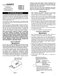
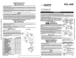
4. Run flexible tubing or pipe from evaporator drain into one of
the three pump inlets. Be sure inlet piping is sloped downward
to allow gravity flow (Figure 3). Extend the inlet piping into the
tank from 1 to 3 inches to ensure that it will not interfere with
proper float operation. Be sure that the inlet piping is cut at an
angle where it enters the tank.
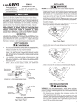
3. Test motor switch by raising motor switch float with finger (Figure
6). Motor should turn on just before float contacts cover.
4. Test safety switch by raising safety switch float with finger.
Safety switch should activate before float contacts cover.
5. Replace motor/tank cover assembly on tank.
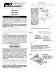
5. The outlet piping should be flexible tubing secured with a hose
clamp (not provided) or pipe (3/8 inch I.D. maximum to prevent
excessive flow back to unit). From condensate unit, extend
discharge piping straight up as high as necessary. Do not
extend this line above the head/GPH of the particular model
being installed. From this high point, slope discharge line
down slightly to a point above drain area; then turn down and
extend to a point below or approximately level with the bottom
of the condensate unit. This will give a siphoning effect which
will improve efficiency of the condensate unit and will, in most
cases, eliminate the need for a check valve (Figure 2). If it is not
possible to slope discharge line down, make an inverted “U”
trap directly above the pump at the highest point.
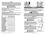
This pump is suitable for gas furnace condensate applications.
Caution must be taken to ensure acidity of condensate does
not increase below the average pH of 3.4 (to prevent localized
pocket of acid that acts like a battery causing pitting) by routinely
cleaning or flushing tank with fresh water.
6. Do not install this pump in a manner that will subject it to
splashing or spraying.
4. Check the inlet and outlet piping. Clean as necessary. Be sure
there are no kinks in the line that would inhibit flow.
7. Do not install this pump inside air plenums.
ELECTRICAL CONNECTIONS
1. Shut off electrical power at fuse box before making any
connections. All wiring must comply with local codes.
2. Connect power cord to line voltage specified on motor and
nameplate. Power cord must be connected to a constant source
of power (not a fan or other device that runs intermittently).
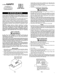
3. The safety overflow switch should be connected to a class II
low voltage circuit. To control a thermostatic circuit the COM
and NO connections from the safety switch are to be wired
in series with the low voltage thermostat circuit to shut down
the heating/AC circuit. The COM and NC switch contacts may
be used to actuate a low voltage alarm circuit (connected in
series) if the heating/cooling system can not be disrupted. The
safety switch comes from the factory with leads connected to
the COM and NO switch terminals. Typical hook-up of “NC”
circuits would be (Figures 4 & 5).
SERVICE INSTRUCTIONS
1. Make certain that the unit is disconnected from the power source
before attempting to service or remove any component!
2. Be sure the floats move freely. Clean as necessary (Figure 6).
3. Clean the tank with warm water and mild soap.
FR
INTRODUCTION
La présente notice d’emploi comporte tous les renseignements
nécessaires pour utiliser en toute sécurité les pompes Coleman.
Garder le présent document pour référence ultérieure.
Les pompes Coleman sont soigneusement emballées, et testées
pour assurer une livraison et un fonctionnement sans problèmes.
Lorsque vous recevez votre pompe, examinez-la attentivement
pour vous assurer qu’il n’y a pas eu de pièce cassée ou
endommagée pendant l’acheminement. S’il y a eu des dégats,
prenez-en note et signalez-le au magasin où vous avez acheté la
pompe. Ils vous aideront pour le remplacement ou la réparation,
TESTING
1. Turn on power.
2. Remove the motor/tank cover assembly and hold it level.
Figure 5
Safety switch float
Commutateur de sécurité de flotteur
Flotador del interruptor de seguridad
Motor switch float
Commutateur de moteur de flotteur
Flotador del interruptor de motor
Figure 4
2
Figure 6