1
(!)rqoNEEn
ORDERNO.
ARP-141-0
STEREOTURNTABLE
PL-AAF
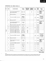
MODEL PL€8F COMESIN SIX VERSIONSDISTINGUISHED
AS FOLLOWS:
Typ
.
.
.
.
vohagc
Remarka
KU
12OVonly
U.S,A.model
KC
1 2 0 Vo n l y
C€nadamodel
220V and 24OV {Switchabls}
Europemodel
HB
220V and 240V (Slyitchablel
U.K. model
s
110V, 120V, 220V and 240V (Switchabte)
Generalexport model
s/G
1lOV, 12OV,22OV and 240V Switchabte
U.S.militarymodel
This is the servicemanualfor modelPL-88F/KU.For servicing
of KC,HE,HB.S and S/G types,
pleaerefer to the additional servicemanualon page45,
For the circuit& mechanism
description,pleasereferto the PL€8F servicemanual(ARP-I113).
Ce manueld'instruction se refdreau modede r6ghge,en frangais.
Estemanualde serviciotrata del metodo de ajusteescritoen espafrol.
CONTENTS
1.SPECTF|CAT|O
. .N
. .S
..
2 . F R O N TP A N E LF A C I L I T I E .S. . . . . , . . . . . . .
3. DISASSEMBLY
4. EXPLODED
VIEWS.
5. PACKTNG
. . .. .. .
6 . P . C .B O A R D S
C O N N E C T I ODNI A G R A M. . . . .
7 . S C H E M A T IDCT A G R A M
..........
8 . E L E C T R I C APLA R T S . .
.........20
9. ADJUSTMENTS
. . .. .. .
nEolnce
2
3
5
6
13
14
17
23
...........30
AJUSTE.
............37
A D D I T I O N A LS ER V I C EM A N U A . _
(For KC,HE.HB,S,S/c types)
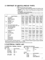
1 . S P E C | F | C A T | O. N
. .S. . .
........45
2 . C O N T R A SO
T F MISCELLANEOU
PS
A R T S. . . 4 7
3 . E L E C T R f C APLA R T SL | S T
.......
47
4. SCHEMATIC
DIAGRAM
(KC,HE,HB,S,ST
/ GY P E S )
.......
49
5 . P . C .B O A R DA S S E M B L Y
. ...... . 52
PIGINEEFI
ELECTFICINIC
CGIFIPCIFIATION
a r, Mesu.o r-chome, Mesu.o-ku, Tokyo.r53. Japan
PIG'NEEFI ELECTFIC'NIC:3
lNC.
1s25 E. Domnguez
Sc., Long Beach, Catifo.na 9OA1O U.S.A.
llJaAl
PIONEEFI
ELECTFICINIc
N.v.
Keerbe.gtea.'
1,2740
E}evenen, Etetsium
[EUFIclPEI
Pf ONEEFI ELECTFTCINIC€1 ALJSlFtALlA
PTY. Ltll,
17A-1e4 Boundar'y Fosd, B.aes cle, Victo.is 3195, Austnata
FFO
AUG. 1982
P r i n t e di n , a p a n
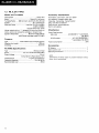
1. SPECIFICATIONS
Motor and Turntable
Accessory mechanisms
Direct-drive
DriveSystem
O u a r t zP L LH a l lm o t o r
Motor.........
TurntablePlatter.....280mm diam. aluminumalloy die-cast
33-1/3and z[5rPm
Speeds
*
o RMS)
L e s s t h a n O . 0 1 2 V{ W
W o w a n d F l u t t e r. . . . . . . .
(WRMS)
0.025o/o
i 0 . 0 3 5 %W T D P e a k( D l N )
Valuesmarkedwith an "*" designatethe wow and flutter for
motor, and do not includethe cartridgeor tonearm load.
Morethan78 dB (DIN-B)
Signal-to-Noise-Ratio
{with PioneercartridgemodelPC-41MC)
Auto lead-in,auto return, auto cut, repeat
Arm elevation,programsearchPlay
Index play, manualplay, manuallocation
Skip, auto disc sizeselector
Deck synchro, recorddetection
Built-inanti-skating
Tonearm
type, Straightpipearm
Static-balance
Type . .. . .. . . . .
..'. 208 mm
Arm Length
Effective
.2O.2mm
Overhang
PC-41M C Specifications
Type .........
S t y l u s. . . . . . . . .
outPutVortas"
F o r c e. . . . . . . . .
Tracking
FrequencyResponse
Load
Recommended
. . . . .M o v i n gc o i lt y p e
. 0 . 3x 0 . 7 m i l d i a m o n(dP N - 4 1 M C )
ii kH;.50;;;;;;;;;;i*1il'-l
1 . 7g t o 2 ' 3 9 ( p r o p e r 2 g )
10to 35,000Hz
"""" 50 ko
Miscellaneous
A C 1 2 0V , 6 0 H z
P o w e rR e q u i r e m e n t s
P o w e rC o n s u m p t i o n
. . . . . . . . .2 1 W
. . 4 2 0 ( W )x 9 8 { H ) x 3 3 5 ( D ) m m
Dimensions
(D)in.
1 6 - 1 1 (2W ) x 3 - 3 / a( H ) x 1 3 - 1 1 4
. . . . . . . 1 0 . 3k g / 2 2 1 b1 1 o z
Weight
Accessories
E PA d a p t o r
D e c ks y n c h r oc o r d . . . . . . . . . . .
O p e r a t i n gI n s t r u c t i o n s
........1
. . . . . . . . . . . . . . . . . . . . .1. . . . .
. . . . . . . . . . . .1
NOTE:
Specifications and design subject to possible modification
notice, due to improvements.
without
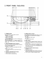
2. FRONT PANEL FACILITIES
o poweR switch
Pressthis switch to turn the power on and off.
Depressed( ) position:
Power is switched ON.
Released( r
)position:
Power is switched OFF.
When the POWERswitch is set to ON, the following switchesareset automatically.
ARM ELEVATION
switch- UP. MANUAL ARM SET/CUT
s w i t c h - + O F F , R E P E A Ts w i t c h- + O F F , S P E E Ds e l e c t o r
switch -+ 33
@ o e c r s YN cH R o sw i tch /i n d i cator
This switch is usedwhen a tape deck has beenconnectedto
this unit usingthe accessory
cord.
Depressed( ) position:
For operationswhich are synchronized
with the tape
deck.
Released( I
)position:
For operationswhich are not svnchronized
with the
tape deck.
switch
@ naaruuAlARM SET/CUT
r Pressthis switchfor manualplay.
o Pressthis switch to stop manualplay.
@ SPeeOselectorswitch
This is pressedso that the speedindicatorlights in line with
the rated speedof the recordwhich is to be played.
"(33)" lights:
For playing33-1/3rpmrecords.
"(45)" lights:
For playing45 rpm records.
@ SflP swatch
r
When this switch is pressedduring play, the play of the
current track is suspendedand the stylus starts playing
the next track.
o When the switch is pressedduring programmedplay,
the play of the current track is suspendedand the
stylus moves on to the next track programmedand
startsplayingthat track.
@ STOPswitch/ARMLOCATEswitch/
indicator( ) )
o Pressto stop auto play.
r Presswhen movingthe tonearmtowardthe right (in the
directionof the outsideof the record)duringmanualplay.
o Pressthis switchto release
the programfunction.
o
O START switch/ARMLOCATEswitch/
indicator( < )
o Pressto start automaticor programmedplay,
r Presswhen moving the tonearm toward the left (in the
directionof the insideof the record)during manualplay.
o When the switch is pressedduring actual play {whether
automatic,programmedor index),a returnis madeto the
first track (or the first programmedtrack with programmed play) and play begins(re-startfunction).
@ operulclosEswitch
r This is pressedto open and close the door and to bring
out and retractthe slide base.
o lt is also pressedto stop auto play.
@ lruOexSCANswitch/indicator
Pressfor indexplay.The indicatorflashesduringplay.When
pressedagain(the indicatorgoes off), index play is released
and the normal auto play or programmedplay mode is
established.
switch/indicator(UPl
@ anrta ELEVATION
r Pressthis switch to start manualplay.
o Use the switch to suspendrecord play temporarily.
' Usethe switchwhen changingthe tracksduring manual
play.
"UP" indicatorlights
The tonearmrises(the stylus movesaway from the
record).
"UP" indicatorgoes off
The tonearmdescends(the stylus is loweredonto the
record).
@ nePeef switch/indicator
Pressthis switch so that the indicatorlightsfor repeatplay.
@ pnocnAM SEARGHswitches
o Pressthese switches in the desiredsequencefrom [1]
through [8] when programmingthe order in which the
tracksareto be played.The tracksare programmedin the
order in which the switcheswere pressed,and auto play,
repeatplay or index play is performed.
The numbers[1] through [8] indicatethe order of the
tracks on the record (for instance,the [2] switch correspondswith the secondtrack).
The programmedplay function is releasedwhen play
endsor play is suspended.
Programmedplay is releasedwhen the stop switch is
pressed.Pressthis switch when you havemadea mistake
in the programming.
@ eP adaptor/EP adaptor holder
Slide the EP adaptorover the plattershaft when the record
you want to play does not havea "middle".
Keep the adaptoron the holderwhen it is not in use.
NOTE:
Make sure that you use the EP adaptor which is supplied with this
unit. Using any other adaptor may invite contact with the stylus
with the rcsult that the stylus may be damaged.
@ Speed indicators (3|,451
Theseindicatethe platterspeed.
"(33) lights:
Platteris rotatingat 33-1/3 rpm.
"(45)" lights:
Platteris rotatingat 45 rpm.
@ Ouartz Lock indicator
This lightswhen the platteris rotatingat its 3X|-113
or 45 rpm
speed.
@ Bonnet
@ stide base
@ Platter
@ nuUUermat
NOTE:
Always use the rubber mat which is supplied with this unit. Using
a different rubber mat will change the stylus height and may cause
malfunctions.
@ Platter shaft
@ Tonearm
@ Headshell
@ Cartridge (PC-41MCl
@ Sensitivity selector switch
Set to the position that correspondsto the type of record.
This switch is normallyset to the "NORM,, position.
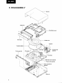
3. DISASSEMBLY
Escutcheoncover
Turntable platter
Tonearmbase
asembly
Slide basecover assembly
Powercord assembly
Powertransformer
asembly
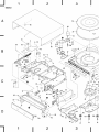
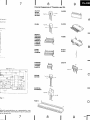
4. EXPLODED VIEWS
'
NO?ES:
o Parts without part number cannot be supplied.
c The A mark found, on some component parts indicates the importance of the
safety factor of the part. Therefore, when replacing, be sure to use parts of identical
designation.
o For your
Parts Stoch Control, the fast mouing items are indicated with the
marhs**and*.
**
1ENERALLYMovEs
FAITERTHAN*
This classification shall be adiusted by each distributor because it depends on model
number, temperature, humidity, etc.
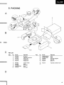
4.1 TONEARM
PartsList
Mark
No.
i
* *
* *
* *
**
* *
o
Part No.
Description
1.
2.
3.
4.
5.
XWX-O8S
PXT484
PXV-OOI
PNX-391
ZMK4OHlOOFBT
Coil assembly
C o i lu n i t
EV sheetunit
Tonearmbase
Screw
6.
7,
8.
9.
10.
PBH-326
ZMD40HO60FBT
PXB-271
YS4OFBT
WB4OFMC
EV spring
Screw
Magnetassembly
Washer
Flat washer
41.
42.
43,
44.
45.
pBA-b37
pDE-172
pNC-245
yEbOS
ppZ3OpOgOFMC
Cartridgemountingscrew
Connectorassembly(gp)
plate
Washer
Screw
1 1.
12.
13.
14.
15.
PBE-019
PNX-392
PBH-327
PEB-185
YE30S
PU springwasher
Adjustingcam
Spring
Belt
Washer
46.
47.
4.
49.
50.
pBA-139
NC5OFMC
PMZ2OPO4OFMC
pED-024
ZMKSOH1OOFBT
Screw
Nut
Screw
Cushion
Screw
16.
17.
18.
19.
20.
PNX-396
PNX-395
PNX-394
PSH-OO7
PNW-392
Gear(C)
Gear(B)
Gear(A)
Slideswitch
Motor pulley
51.
PNR-533
Weight
21.
22.
23.
24.
25.
PXM-118
PPZ30P50FMC
PBK-057
PNX-398
PEO-O22
Motor
Screw
Platespring
Leadin ratch
Cushion
26.
27.
28.
29.
30.
PNX-397
PSH-004
XWXO84
PNX-399
PNX400
Drivingplate
Slideswitch
LED assembly
Sensorholder(A)
Sensorholder(B)
31, XWX-083
Phototransistorassembly
33.
U, PNX-376
35. PNP-254
Sensorcase
SensorP.C.board
Mark
No.
**
*
t
Part No,
36. pCXOsg
37. NJL11O2EH
38. PBH-32S
39. pLB-lbl
40. pLB-1S2
101.
1O2.
103.
104.
1OS.
Description
Transistor
LED
Spring
Adjustingscrew
Nut
ptateA unit
Hotder
Baseassembly
E
"fft-40
I le-;N
3e
| $-tu
t-S-g+
,b [-.st
2
I
-l
I
I
Io
,--l
I-nu
-Q-27
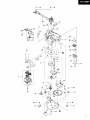
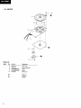
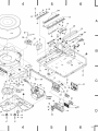
4.2 MOTOR
th
I
16);
4-d
PartsList
Mark
No.
Part No.
Description
;
PXT.473
PWM-I15
PSZ3OPOSOFMC
PSZ3OPOSOFMC
PEC-030
Rotor unit
Control assembly
Screw
Screw
Wire clamp
2.
3.
4.
5.
50.
51.
52.
Base unit
Heat sink
Stopper
l+
s--€
I
4 . 3 E X T ER IOR
PartsList
Mark
No.
Part No.
1 . PNA.17O
2 . XWR-O4O
3 . PSH{O7
4 " PNX.425
t*
Description
PNX-437
6.
7.
8.
9.
10.
PNX-436
PBA-126
XWX-126
PEB-2O7
PXB-291
Gear(F)
Screw
PU assembly
1 1.
12.
13.
14.
15.
PED€23
PNX.435
YE255
PNX-440
PNX.378
Rubber cushion
Slider
Washer
Pulley
Front door
16.
17.
18.
19.
20.
PNX-438
PBK.O58
PBH.342
PNX-387
Door holder (L)
Spring
Spring
P knob
**21
.
*t
22.
23.
24.
25.
PSG.O37
PSF-018
XWM.134
PNX.389
PBH-339
Pushswitch
Microswitch
Control assembly
Power switch lever
Spring
26.
27.
28.
29.
30.
PEB-2O4
PNR-175
PXM-121
PNX449
PEB-184
Rubber mat assembly
Turntable platter
Motor
Motor pulley
**
*
*
**
3 1 . PNX.43O
32. wA41 D065D025
33. YE3OS
u . PNX429
35. wA31D054D025
Gear ( E)
Flat washer
Washer
Gear (D)
36.
37.
38.
39.
40.
Y E2OS
PE8-206
PXB.265
GL.gPG12
G L-gPR12
Washer
Belt
Slide base cover assembly
LED
LED
4 1 . XWX-086
42. PNY-026
Speed indicator assembly
Cover (KU Type)
Cover (KC,H E,HB,S.S/G)
PNX441
43. PAC-I15
44. XWX.O87
4 s . PXM-122
46.
47.
44.
49.
50.
Flat washer
Slide knob
Sensibility selector assembly
Motor assembly
PEB-234
PEB.212
Damper rubber (C) (KU)
Damper rubber (A)
(KC,HE,HB,S,S/G)
PBA.141
PEB-208
PBH.336
PBA-140
Screw (B)
Damper rubber
Spring (B)
Screw (A)
Part No.
53.
54. PNX-424
55. PNX-434
56.
57.
58.
59.
60.
Cushion
Escutcheon cover assembly
Rubber cushion
No.
51. PNX-442
52. PTXO32
Bonnet
Power supply assembly
Slide switch
Lamp cover
Driving lever lack
o.
**
**
Mark
PNX-433
PNX432
PNX-431
PNC-251
PNX-428
61.
62.
63. P N X . 2 3 1
64; PNX-426
65. PNC-253
Lr
Dolcrifiion
45 adaptor
Powertransformerassembly
{ 120v)
Shaft
Roller
Lock leverroller
Lock lever
Lock plate
Loweringrack
Sliderail
Slide rail rack
Steelball 4@
Steelball 60
Gear
Retainer
Rail cover
66.
67'
68.
69.
70.
PDF.178
PDE-l97
PEC-048
PEC-051
XWX-129
Powercord assembly
PU cord
Strain relief (Powercord)
Strain relief (PU cord)
A
RegulatorlC assembly
71.
72.
73.
74
75.
XWX-130
PEC-082
PNX-406
PXB-278
PNX-403
B
BegulatorlC assembly
Stopper
Operationpanel
Rollerangleassembly
Front panel(C)
76.
77.
78.
79.
80.
PNX-407
PNX-388
PNX-386
PNX-413
PWX-O69
Panelholder
SPknob
DS knob
Lens(Al
Functionassembly
8 1.
82.
83.
44.
85.
PNX-410
PNX-414
PNX412
PBH-328
PAD-l01
EV knob
Lens( B)
Selectorknob
Knob spring
O/C knob unit
86.
87.
88.
89.
90.
PAD.102
PAD-103
PAD-104
PNX-450
PPZ3OPO60FZK
Start knob unit
Stop knob unit
Skip knob unit
Wireguide
Screw
91.
92.
93.
94.
95.
PDE-151
PPZ3@080FMC
tPz30P100FMC
wA30F100M100
lD230P080FMC
(2P)
Connectorassembly
Screw
Screw
Flat washer
Screw
96.
97.
98.
99.
100.
PPZ26PO50FZK
rPZ30P160FMC
PBA-125
PBA-088
lPz3oP080FMc
Screw
Screw
Screw
Screw
Screw
**
No.
Part No,
Description
No.
101.
102.
108.
1U.
105.
PMA40P060FMC
rD23oP060FMC
PDZ3oP060FZK
PDZ3oPo5oFMC
lDZ30PO80FMC
Screw
Screw
Screw
Screw
Screw
121. PNX468
122. PMA30P080FMC
123. PE8-235
P E B . 231
Wire hold
Screw
Damperrubber(D) (KU)
Damperrubber(B)
(KC,HE,HB,S.S/G)
106.
107.
108.
109.
110.
PEB-213
XWX-125
PSH{09
PNX439
P Y Y - I1 5
Damperrubber (B)
Jack assembly
Slideswitch
Door holder{R)
Door holderassembly
201.
202.
203.
2U.
205.
Stopper
Angle assembly
Gearbase
Roller catch
Float base
111.
112.
113.
114.
115.
PMZ30P150FMC
PBA-138
WA41D065D025
PDZ30P060FMC
Screw
Screw
Flat washer
Screw
206.
207.
208.
Baseunit
Wire
Cover
116.
117.
118.
119.
12O.
PDZ30P080FMC
WH30FMC
PEB-211
PBA-126
PDF-166
Screw
Washer
Rubber
Screw
GND leadunit
Part No,
Description
1
2
3
A
_30
98
B
'49 e2
I
rrebr ,!+
C
7
44 rie I to
e
I
ree
3
ff4-zz
ru2---a-97
24
t'If
25 109
,"1
t8
D
b-go
\gz
l-
''
ffi"_
\ 92
l-
92
I
q ,rr-6
F
,tr.k
I
47
2
.\
(a)l
\-.
l+o
v/
1
((oc
er*
A
I
I
47
4
6
5
33
--33
/r+
A
63
62 1
\"9
/'z
B
2=;-
'l
?
I
72
I'
1 r 7) o
44 92
ree
-t04
C
r16| 'lo
92
ffit20
t05
Motor Ass'y
(8 page)
t04
Tonearm
(6 page)
84
\
so\6
v
,,46 Y
r23-g
A
I
I
47
I 3"
k
85
@zl
t:
| \
l-o
87
lS-*
79
I
82
3*J
8392
D
roo-@E--on
g o-50
I
47
4
5
6
12r
5. PACKING
o{s
6 r-)
B
-
2,10
PartsLlst
M-k
l,lo.
1.
2.
3.
4.
5.
6.
7.
8.
9.
10.
Prt No.
Derripltion
No.
Pr.l No,
Dartiplion
PNX{42
PRe-220
PHHO't6
PHA-I46
PHA-147
45 adaptor
Op€ratinginstructions
Packingcale
P.otector lF)
Protector (Rl
11.
12,
'l3.
PMB40P160FMC
lPz30P120FMC
PRW-@8
PBA-141
PNX.474
Scraw
Scrsw
Note paper{6daptor)
ScrelY(B)
(Al
SDacer
PNX451
PNX.452
PRWO96
|PZ40P250FMC
PRN{I5
Ton6arm holder
Spacar
Not6 pap€r
Screw
Note paper
'|6.
17.
PDE-157
Tsoe deck connectioncord
14.
15.
lrl
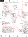
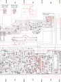
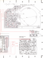
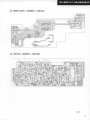
6. P.C.BOARDS CONNECTIONDIAGRAM
II
3
I
REGULATOR
lC Ass'y (B)
(xwx- I eo)
PHOTO
TRANSISTOR
Ass'y
(xwx -oa3)
LED Ass'y (XWX-Oa4)
H-qfu
A
420t,?o2
a2a3,?o4
sE302a
sRlo6D-Lc
"'"'{d, 6*.
^l
6
Q*
cot L
P.C. BOARD Ass'y
( x w x-o e s )
:jry"'
NO(RESET)
c1
lo
t??
g W2OZ
fr*'
o
i3?tll"
lA2otl
l$' J
?83?sg"
o
'*or# o
oro{,ro2 2scr8i5
rcro3
sA6t09
NC(UP)
I
__'
I CI 04
i,tSSzlOOrB
D{Ot,lo? wLoz
oro3
ts?473
4t{tr*
w203
220 | Bl
yr:
ss:DowN
TONEARM
MOTOR
SENSIBILITY
SELECTOR
(xwx- oe7)
*{/*=l
."J: !f!
Ass'y
.*5J::"
CONTROL
"i%;jj.
(xwM- r34)
LOAOING
MOTOR
---)
D
n
{--r
47o'
F+
Hcrs:
#o*-o
6l
I
I
I
.?3S"tS"%no
,+IiJ.+,it
rt-j"".i:
:'
o
?
JACK Ass'y
(xwx- | 2s)
, , ,lt -,:i--.'l
,.::i
e
.
o l-
-
-l
.m,
if #'ii'-Jr;1:
"?ii #
l[-rJ:gi:i.
:?r- i
lffiunr.o
1
|c2 NJM29OIN
1C3,6 NJM4558O ot
9PC455EC q-Cl2
o.e"
o{}4
324 4?Ol
PU P.C. BOARD Ass'y (XwX- | 26)
---a
I
nzass,
ffff
Ass'y
2
3
+
Rat 2rA
I
II
4
REGULATOR
lC Ass'y(B)
REGULATOR
lC Ass'y(A)
(xwx- | 30)
lG-=;41
5
TRANSFORMER
6
As s'y
lxwx- rzs)
ul
____JFlt
'lll
lf
POWER
.-
.".11''
II r;rcror |
l--G@;- I
rcro2
0
I
|
'iaioi-
|
NJM78'{.a
NJM 78iIOsA
POWER
SUPPLY
(xwR -o4o)
ll
I
ctoT
o.or
GIF
croo j
5
tezz!--
o'
I cro3
II
I
I
TRz3 C*
Rtor
r80 t?*l
(!""--..,.*-.H
raes(F--
o'3' tR2g lF-
,f\
h"r
qo2
orct,1o2 esctSt5
rctos
BA6iO9
tcto4
MgSrrootB
0ror,to2wt.oz
0{03
,rs2473
J.\
br
0
i
AC | 20V
60Hz
56:POwER
tc2
{l
Q2
oz !lo"
( rc2 NJM2gO{N
| 1C3,6 NJM4558O or
IPC455ECH
t
d
Hl
I gg :.,"nqtr*
t
:n:
I '*f*t'o'. ? t ,
H rael
m* l|:.;,li
; :[-1: J J ol*l
, c, ,.
]lrJ:'L
r gt,r
."*-
l'-'l'x'l',
I
' I' r F;t;-.
F-l.
I I
Utl^."1t l.-
o.:g;x
*6',,,
:
?rrt.^l|:-]l ,I
:i[Iis'f
ii'"l1-:F
I I l:
'u,*;"'A* I "3frg1
t-,Jl*l
-
4iT
.'---l
or
NI
'l
l. T
f*l
:t.,+rl
.t Il n
6
?'I
I
|
i
,'
I'-l
*
Ill
;
*a r, B&".t
i?tsr,
ilt
ri
'J
s?
17.3
ARM
MOVE
ill
]}u
I t'-i",
l.d"
F-+-"3,,*{
i^."1**f
I
ry]Iff"lf'"i
L
I
I
'K.N}'rJP'
:l'"1:
I
'
'l l" ?
I
:f "l:Il * l #$fl8
-I?.
.+'i
",
16
a€
??'fl lerl
/ro
L{
l.{
El I
|ti Tl
I
l"
R54
ror
I
/ MoroR
/ srop
A qre
taAt rol,
L/
'u
I
/2 &'slxf*
?
t
l*
T{7r
;JbJ'"i
1T
l:
?l
E
lr
,I
/*hll
l^,{t lbj'l
+r
wf
lI
a
o"l"
??
lt ll l '
F
Ra2
22t
H
ad
a4 2SCr959 09
4
5
6
R3t
r---nF
llt
7
I
CONTROL
Ass'y (PWM-
122)
#* 3:i
/
/
;;:-'
.f,ti
l'tt'
t:fl
fffwtl
I
I I
,s . F-1.
ol
lo
. 1 . ,, ' ,1 "1 "
,lo
ro.e.l
"ll.r_
"[4_:l
l"
'
HB
I I
g;. o&J ll
|."*mt68r "------;- ho
ll
----fts
Fl
l'I
ll
, --!i*ra
*t "-----:
.
t
A
t
| '"' |
|
I
I
a
li-E--;Jlno
$:ffi {*r
o
o
o
5.rs
Rxz4o ?
|
^t--'|t::-
I |
-, 9f,
Ef' 'bi:- ' I
l"l
{3 r
Ess-.""ar,ttf.fl
":ef
,0.%
L I
i-F
o.il1,"
fl-t",o
-lt{
e-
oo,
" I "#1?;#d-1t1II
:
flfR'1..1'"1
r I -.f
I
|
| lt
r
tl/r
erF
, r r " o l// ".
r6.a(
tsJ l.€
cr 33p
*iDf"
x'TA!
.
I
t
lr"
t"ro'iffi"
p
o
?
rcr pa2@7
u,"l 4lol' *:: *r,
i33Ft''Sg
6ri6 rC4 TO625O3p
|
^b/t6
06;
I
'' '
"
'
lr, l" i ,'^t ^
or
Qr 2scr8r5
o
I
i
I
o40r
GL-9PRr2
0402,403 GL-gPGr2
SPEED
INDICATOR
Ass'y
(xwx -oa6)
JX8; rquanDri'LocK)s,
.@i
FUNCTION
R'\
r.rr xr I
rf|tl
( Pwx - o6e)
'oi
rhP-
q
Ass'y
C
I
l" l F l f
lol lol I
l . ll " l r
'qEf"q
ff*m*=*,b$;,,
I Ilk'll*:.
l-el Bi
Rr 200
+m"il+mFj"i.H
i--.ii#li%*
r----{i*+
R2 200
Hr{.<
Rl
200
o--{lH
R4 75
r*[51
33r
loJ
xaI I
l"l
l"l
l*Hs
tffiffiffi
BH"wrm,Htffi"nN
-d{r
e^
i9.-.lfi
i9..lHl
i9^lkll
:Jl
*- rui
*qipTilq*f
-l
L:J
,Tg
4/t6
-
lT-ll
-
f?-l
";1i f?-l
-
+
[1]
ffijf'
Q3O{r 3O4
2SA874F 6
2SA854
O3oltu 3Oa DAN2OIF
D3O9! 32O
GL- 9 PR.I2
oa2t,322
GL- 9NGI 2
7
L,
MAttUAL
s3r7 ARM SET
5316
.o{
l?;il l*--1--l
l
llE
(sYNcHRo)
l*;1]J
l:^-
I
D
2
3
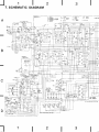
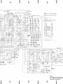
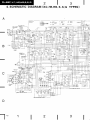
7. SCHEMATIC DIAGRAM
A
RJ PC BOARDAss'y
xwx- i26
oo,---;
l;-E NJMo-;;;-------;;;;;,
I u*x scrua.
""r:::-,";;.
PCP
I
via
Na
_Of1
OFFS€I
2
tct
PD6ot3
lcz NJMz9OIN
1C3,6 NJM455AO or PPC4358C
lC4 MAa4O668 d 'C4O66BP
rc3 NJM4556O
tc7 M53207P
ot
2sciat5
O2.3,5,6,8
2SC245A
d
2SCl8t3
04
2SCt959
q
2SAiO48
2SArOr5
2 S C r 8 15
iS24Z5 d
0l!6
rsr555
Q7
04N20{F
RO3.6EA
07, I
Dro
ot rswlTcHll{G
( START-ON )
09
06:
BANO SERVO
I
|
AOJ
P C P- O r 2
22O
L---..i
PHOrOrFAlSrSr&
rcx- o59
CARTR I06E
IN
B
R€LAY
PSR-OO4
_
SENSIBILITY
SELECTOR Ass'y
xwx - o87
5{l
P5X-@A
AC P@ER
COm
Art
IX LEAO N.L
t
R€TURN
c&1
A
r-
rcWEF I&S'OFff
PJX-O!2
_ _Ard,
/fi
I
I
rc20r
aA520E
M O T O RD R I V E R
- r$^881,tssB
SAo"t
COIL PC BOARO Ass'y
|l r
**l **L
Q20t*
2Q4
|
_
P|{OTO TRAiISISTOR As}
XWX-O83
L:a:'"-I"-
1
2
3
XwX -O85
4
6
5
roie6€)
sl. cLosE
PSH-@7
I
r c I O P E N)
52 OP€N
P5H - O@
t(
FUNCTTON Ass'y
l - - -s -! 6 . 1 r 7
I
I
srre
RESISTORS
Indicated in !t. v.W, ,r. W r5% rolerance uniss otherwr*
nored k k
M. Mrl. (F). ,1%. (G), '2%, (K)..10%
{ t ! , ! ) .' 2 0 % r o t e r a n c e
2 CAPACITORS
(!F)lvolrage
(V) !nless orh€rwr*
lndic.td
In cpacLty
p. pF lndrcatton w,thNl
vollage rs sOV except el6lrolylrc
pWX -069
: Psc-oao
. Ps6-o39
noled
capacl
3 VOLTAGE
DC vottage (Vial
Il
no ]npur rgnal
4 OTHERS
pornl
A
^Adjuslrng
The
A mark lound on some component parts Indrcates rhe rm
portancFoJ the safetv lactor ol the part Therelore when ret)lacrng
be ar€ to use parts ol rdenr ca desrqnalron
4 markd cap&rlors and resrslors have parls numbers
SWITCHES
ON - OFF
ON _OFF
SI
CLOSE
52
OPEN
53
54
s5
RESET
UP
DOWN
s6
POWER
ON _ OFF
ON _ OFF
ON - OFF
ON -glE
sSoi
PRoGRAM
STARCH
i
S3O2
PROGRAM
SEARCH
2
ON . gll
ON . qII
PROGRAM
SEARCH
3
ON
S3O4
PROGRAM
SEArcH
4
s3o5
PROGRAM
SEARCH
s
s3o6
PROGRAM
SEARCH 6
S3O7
PROGRAM
SEARCH 7
ON _ OFF
ON - QI!
ON - gII
ON _ OFF
S3O8
PROGRAM
SEARCHS
S3O9
INOEX
S3IO
START
s3o3
s3r 1
.
sloP
S3I2
OPEN / CLOSE
S3I3
REPEIT
s3r4
sKrP
S3I5
ARM
ON . OFF
ON - OF F
ELEVATION
SPEEo
S3I7
MANUAL
33
ARM SET
S3IA
OECX
S4OI
SENS EILITY
ON.Otr
ON _ OFF
ON _ OFF
ON _ OFF
SCAN
5316
gI!
SYNCBRO
ON - OFF
-45tpn
t/3rpm
ON
OFF
ON
OFF
SELECTOR
HtGH
N O R t r 4_
LOW
s lra
1B
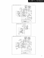
o
03Ol! 3O8
o3O9r 320
o32t,322
OAN2OiF
GL.9PRI2
GL-9NGI2
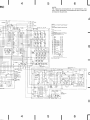
MOTOR CONTROL Ass,y
PWM - r22_
JACK Ass'y I
xwx-,t25
I
O€CX
SYNCHRO
NO tRESIl
rc2 MOT
O RI V
sl ffisET
P S H -@ 7
g:ll
PsH-@'
h:1":H
rc20r
MOTOR
8A6208
vF2or,zoz
DRIvER
[?9t-s&B9itss8
vP&!
Erc ssa
pcp-o55
clNcEL LEvtL
PcP -orf,
roJ
&
I
|
|
lcf
rcz
|
PAzoo7
PA200a
ol
i3: f3:83""
2sct8t5
2sc945
or
01 {s2473
BoARO
Ass'y XWX-O85
040{
GL- gPRr2
NOTE:
The indicated semiconductors a
only. Other alternatiue semicond
are listed in the parts list.
4
5
6
BI
7
I
ExternalAppearanceof Transistorsand lCs
2SA1015
2SC945
2SC1815
2SC1959
BA6208
2SA854
8A6109
[d
otherwrs notd
k, kt]
Itl)..20%
roterance
nl6r otherwr*
epl erftlrolylrc
noted
capacl
Lot No
ans Indrcares the rm
:lore wtren rep acrnq,
)FF
}FF
)FF
M53207P
M88lo66B
M8840698
TC4069BP
M8840018
TErcOl BP
TErc66BP
NJM2gO1N
)FF
)FF
fl
)FF
)FF
}FF
IFF
IFF
IFF
IFF
fF
'l 'l'l '1,'[',
il
a
PA2O(E
r0+ilil++#/
--{
)FF
tFF
PA2007
PDl003
TD52503P
45rpm
"AU
PHl01R
PH101S
n'rlnJ
€
A
0{+il++Mfl
Y
-{
il
U
c
NJM4556D
NJM4558D
pPGrls58C
NJMOT2D
2SA874F
.in44
M++/
-
Type No
Indcr
2SC2458
2SA1o48
tr'.*"S
n,.2\ftfluot
tro
ililli
ililtl
ilillt
.llUII
C UB
NJM7818A
NJM78MO5A
Nr-
Jq
rvceNof\r>l
\ffi/-Lo'No
l/\iU
:ED
ICATOR Assl
x -086
,JJII
PD6013
l:
ndicated semiconductors are representatiue ones
Other alternatiue semiconductors may be used and
ted in the parts list.
lz
lI f
I
B
I
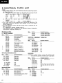
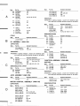
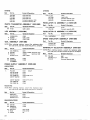
8. ELECTRICAL PARTS LIST
NOTES:
o When ordering resistors, first conuert resistanceualuesinto code form as shown in
the following examples.
Ex. 1 When there are 2 effectiue digits (any d.igit apart from 0), such as 560 ohm
and 47k ohm (toleranceis shown by J=5%,and K=10%).
560a
56 x 101
561 . .. . . RD%PS Eil[iltl] J
47ka
4 7 3 . . . . . R D % P SE n A F j J
47 x 10'
0.5a
0R5..
. . . . R N 2 H @ , ! E 6K
ro
0r0 ..
. . .. asrP [lEto r
Ex. 2 When there are 3 effectiue
resistor:u).
5.62he
562 x I0l
digits (such u
in high precision metal film
5 6 2 1. . . . R N % S R t r @ m E r
c
The [, marh found on some component parts indicates the importance of the
safety factor of the part. Therefore, when replacing, be sure to use parts of
identical designation.
c For your Parts Stoch Control, the fast mouing items are indicated with the
and *
marhs **
**
GENERALLY MOVES FASTER THAN *
This clasification
shall be adjtsted by each distributor because it depends on
model number, temperature, humid,ity, etc:
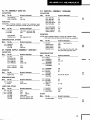
Miscellaneous
Parts
Mark
P.C. BOARD ASSEMBLY
Mark
Partilo.
Symbol& Deccription
PWM-I15
XWM.134
XWX-126
XWX-125
PWX€69
Motor control assembly
Control assembly
PU assembly
Jack assembly
Function assembly
XWX.(83
XWX.()84
XWX085
Photo transistorassembly
LED assembly
Coil assembly
Powersupply assembly
RegulatorlC assemblyA
a
A
xwRo4o
xwx-129
A
xwx-130
xwx.o86
XWX-G7
* *
**
**
A **
* *
*
T
*
* *
Part l{o.
Symbol & Description
PSH€04
PSHOOT
PSH{09
psF-ol8
PSG-037
Slideswitch
Slideswitch
Slideswitch
Microswitch
Pushswitch
NJL11O2EH
GL-gPR12
GL.9PG12
PCX-059
LED
LED
LED
Photo transistor
MOTORS
OTHERS
Mrk
**
**
**
A *
A
Symbol & Description
PDE.171
POE-172
PDE-151
Connectorassembly(4P)
Connectorasembly (8Pl
Connectorassembly(2Pl
CONTROL ASSEMBLY (xwM-134)
CAPACITORS
Mark
RegulatorlC assemblyB
Speedindicatorassembly
Sensibilityselectorassembly
SWITCHES,
SEMICONDUCTORS
Mark
Part I\b.
Part No.
Symbol & Description
c E A 1 0 0 M1 6 L
cEA 100M25L
cEA 220M 10L
C E A R 4 7 M5 O N P
CEA R47M sOL
Cl
C9
C2
C13
C4
C E A 2 R 2 MS O N P
CKDYF 153250
CKDYF 3332 50
coMA223K 50
Cl1
C6
C5
C12
RESISTORS
NOTE:When ordering resistors, conuert the resistance ualue
into code form, and then rewrite the part no. as before.
Mark
*
Part No.
Symbol & Description
PCP-O72
RGSD8X472J
RGSD4X472J
RGSD4X333J
R D / c P MU U U J
VRI
47k
Semi-fixed
R68
R57
R56
R 1 - R 4 , R 6 - R 1 3 ,R 1 5 - R 2 1 ,R 2 3 R32,R34-R55, R59,R81-R85, R87
R86
BD'J4VM1O3J
SEMICONDUCTORS
P.rt No,
Symbol & Descriptbn
PXM-122
P X M -1I 8
PXM-I21
PTX{32
PDF-I7g
Motor assembly(Phono)
Motor (Tonearm)
Motor (Slidebase)
Powertransformerassembly(120V)
Powercord assembly
Mark
**
**
**
**
Part No.
Symbol & Description
PD6013
N J M 2 9 ON1
NJM4558D
(pPc4558Cl
M884066B
(TC4066BP)
rcl
tc2
l c 3 ,t c 6
tc4
Mark
Part No.
**
**
**
NJM4556D
M53207P
2SC1815
(2SC2458)
2SC245A
( 2 S C 1 851)
**
**
**
2SC1959
2SA1048
(2SA1015)
2SC1815-Y
*t
*
152473
( 1 S 15 5 5 1
DAN 201F
RD 3 . 6 E B
K M F C lO OTl
*
*
*
Symbol & Description
lc5
tc7
o1
o4
a7
09
Mark
*
*
D1_D6
D7, D8
D10
osc
Part Nlo.
Symbol & Description
LALO3KH22OK
L1
Part No.
Symbol & Description
CEA 47OM25L
CKDYF 102250
cl4
cl5, Cl6
**
**
**
**
* *.
*
Mark
*
*
Symbol & Description
PCP-074
PCP-012
RDZcVM562J
RD'I4PM
NtrtrJ
VR2, VR3 Semi-fixed6.8k
VR4
Semi-fixed10k
R72
R 6 1 - R 6 8 .R 7 0 .R 7 1 ,R 7 3
SEMICONDUCTOR,
OTHER
Mark
**
**
Part No.
Symbol & Description
NJMOT2D
PSR-004
PDF-165
lc8
Relay
GNDwire
JACK ASSEMBLY{XWX-I25)
Mark
Part No.
Symbol & Description
PKN-O01
Jack
*
*
PCP-066
PCP-052
RNI/4PR363G
RD%PS3R9J
RDTaPM
trtrtrJ
VRI
Semi-fixed47k
VR2
Semi-fixed47k
R3
R10
R l , R 2 , R 5 - R 9 ,R 1 1 - R 1 7
Part No,
Symbol & Description
PA2007
PA200B
PD1003
TD62503P
2SC181s-cR
(2SC945-P)
rcl
tc2
tc3
152473
tu
o1
D1
Part No,
Symbol & Description
PSS-003
PCXOs7
PDE.164
PDE.165
Crystal
Holeelement
Connector4P
Connector5P
FUNCTION ASSEMBLY (PWX-069}
SWITCHES
Mark
* *
**
* *
Part No,
Symbol & Description
PSG_038
PSGO4o
PSG-039
s301-s315
s 3 1 6S
, 317
s318
RESISTORS
NOTE:When ordering resisfors, conuert the resistance ualue
into code form, and. then rewrite the part no. as before.
Mark
MOTOR CONTROLASSEMBLY(PWM-I15)
Part No.
Symbol & Description
RD74PM
trD!J
RGSD4X 333J
R 3 0 1R
, 304-R307
R303
SEMICONDUCTORS
CAPACITORS
Mark
Symbol & Description
OTHERS
NOTE:When ordering resiators, conuert the resistance ualue
into code form, and then rewrite the part no. 6 before.
Part No.
Part No.
SEMICONDUCTORS
Mark
RESISTORS
Mark
c12
c27, C2A,C30
c29
cl4,C16
RESISTORS
CAPACITORS
-
C E A 1 O 1 M1 O L
CEA OlOMsOL
CEA 33OM1OL
cszA R22M 35
NOTE:When ordering resistors, conuert the resistance ualue
into code form, and then rewrite the part no. as before.
PU ASSEMBLY (XWX-126)
Mark
Symbol & Description
a2,o,3,05, 06, 08
OTHER
Mark
Part No.
Part No.
Symbol & Description
ccDcH 330J 50
c o M A 1 2 3 K5 0
coPA 473J 50
CKDYF 1032 50
CKDYF 203250
cl
c5
c8
c2,c4,cl 0,c23
CKDYF104216
ccDcH 560J50
CEA R47M sOL
C E A 1 O O M1 6 L
CEA lOOM35L
c6, c7
c3
c 9 ,c l 5
c24
c18-C22
c 1 1 , C 1 3 ,C 2 5 , C 2 6
Mark
**
*
*
i
Part No,
Symbol & Description
2SA874F-R
(2SA854-cR)
DAN2O1F
GL9PR12
GL-9NG12
0301-0304
D301-D308
D309-D320
D321,D322
OTHERS
Mark
OTHERS
Part No.
Symbol & Description
PNX.446
PNX454
PNX.455
PDE.185
PDE-186
L E D h o l d e r( B )
LED holder(C)
LED holder(D)
Connectorassembly(1OP)
(6P)
Connectorassembly
PHOTO TRANSISTORASSEMBLY (XWX-083)
Mark
**
Part No,
Symbol & Description
PH101
0,201-a2@-
Mark
* *
Partl{o,
Symbol & Description
PEL-051
PNY-OOg
PDE.188
PDE-213
Lamp
Lamp holder
Connector assembly (3P)
Connector assembly (5P)
REGULATORIC ASSEMBLYA (XWX-129)
Mark
**
Part No.
Symbol & Description
NJMTB1BA
PDE.190
Connector assembly (6P)
rc101
LED ASSEMBLY(xwx-084)
REGULATORIC ASSEMBLY B (XWX-130}
Mark
Mark
*
*
Part No,
Symbol & Description
RGS}TX391J
SE3O2A
SR106D-LC
R205
D201,D202
D203,D2U
COIL ASSEMBLY (XWX-085)
**
*
*
**
**
Part No,
Symbol & DescriptSon
C E A l R O Ms O L
PCPOs5
PCP{73
PDZ4PM
D!!J
c201
vR201, VR202 Semi-fixed 4.7k
VR2O3
Semi-fixed 220
R201-R204
8A'6208
M8840698
(TC4069BPl
tc201
tc202
POWERSUPPLYASSEMBLY (XWR-O4O}
CAPACITORS
Mark
l\
PartNo.
Symbol & Description
PCLO4O
cEA 471M 50L
c E A 4 7 1 M2 5 L
c E A 1 R o M5 0 L
CKDYF 10/.250
C101
0.01pF
C102
Cl03
Cl04,C105,C110
C106
C K D Y F1 0 3 2 5 0
cEA 100N1
25L
C E A l O O M1 6 L
c107,c111,C112
c10B
c109
RESISTORS
NOTE:When ordering resistors, conuert the resistance ualue
into code form, and then rewite the part no. as before.
Mark
Part No,
Symbol & Description
RS2PF
18 1J
RN7aPB4R70F
RDI/APM
tr!trJ
R1 0 1
R102
B 1 0 3 - R1 1 0
SEMICONDUCTORS
Maft
Part No.
*r
**
846109
MB840018
(TC4001BP)
** 2SC1815-Y
* WLO2
* 152473
ee
Symbol & Description
rc103
tc104
0 1 0 1, 0 1 0 2
D101,D102
D3
Symbol & Description
NJM78MOsA
1cl02
SPEEDINDICATORASSEMBLY (XWX-086)
Mark
NOTE:When ordering resistors, conuert the resistance ualue
into code form, and then rewrite the part no. os before.
Mark
Part No.
Part l{o,
Symbol & Deseription
RD%PM 122J
RD%PM271J
R404
R405
SENSIBILITY SELECTORASSEMBLY(XWX-087)
NOTE:When ordering resistors, convert the resistance ualue
into code form, and then rewite the part no. as before.
Mark
* *
Part No.
Symbol & Description
PSH-008
R D / 4 P MI N I J
PDE.187
s401
R401-R403
(4p)
Connector
assembly
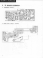
9. ADJUSTMENTS
Dummy Play Mode Setting
The PL-88F can be set to a dummy play mode
(in "loading out" mode) by the following method.
L. Remove the bonnet, and set to "loading out',
mode.
2. Switch the power off.
3. Disconnect the CN3 connector on the control
ass'y, and short pin (1) to pin (2).
4. Then switch the power on, thereby putting the
turntable into play mode.
Notes:
1. When using this setting (bonnet remoued, attd, loding
out mode) for track selection operations and adjustments, mahe sure that the toneann cartridge section is
protected from extraneous lEht.
2. When cheching add.ress-related, operations (including
operatione during track selection snd. play), do not
manipulate the tonearm by hand. If the tonearm has to
be operated,, use the operation heys,
3. Do not operate the OPEN/CLOSE key.
4. Always make sure that the power is off when connecting or disconnecting the connectors.
Adjustments
Different methods af,e usd to adjust the stylus
lowering position for track 1 and the other tracks
for automatic play operation in the PL-88F. The
lowering position for track 1 is adjusted according
to "Stylus Lowering Position Adjustment", while
the lowering position for other tracks is adjusted
according to "Adjustment of Stylus Lowering
Position between Tracks".
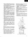
9.1 STYLUS
LOWERING POSITION ADJUST-
M EN T
1. Press the OPEN/CLOSE key, pull the slide base
out forward, place a 30cm record on the turntable platter, and set the correct rpm by the
speed selector.
2. Press the START key to start play. Check the
direction and degree of stylus displacement at
this time. (Estimate the approximate distance in
mm that the stylus lands from the lead-in groove ).
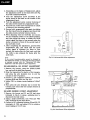
3. Depending on the direction and degree of displacement, adjust the adjustment screw indicated
in Flg. 9.1 with a small screwdriver.
* T\:rn the screw clockwise (a.sseen from above) if
the stylus lowers outsile the lead-in groove.
* Turn the screw counter clockwise (as seen from
above) if the stylus lowers iruide the lead-in
gxoove.
* One half turn of the screw corresponds to a shift
of about 9mm in the lowering position.
4. When using the PLS-2001S test record, adjust
the screw to obtain a count in the 305 to 317
range for lowering onto a 30cm record. And if
the GGF-021 test record is used, adjust to a
count between 6 and 30 for a 30cm record.
Notes:
* R emoualo f t he b o nnet simplifie s adj ustment operat io ns.
In this ca*, ad.juetmentscan be performed. from the
top of the escutcheoncouer,
* Do not incline the turntable ouer too far, nor apply
excessiuepressure to the d,justrnent screw during the
djustment operation.
9.2 ADJUSTMENT OF STYLUS LOWERING
POSITION BETWEEN TRACKS
Use this adjustment method when the stylus
fails to lower correctly into position between tracks
during normal programmed play (when the sensitivity switch is in the NORM position and an
ordinary record is being usd). This position
should also be adjusted after stylus replacements.
1. Pressthe OPEN/CLOSE key, pull the slide base
out forwards, place a 30cm record on the tr:rntable platter, and set the correct rpm by the
speed selector.
2. Press the START key and proceed in progmmmed play mode (excluding the first track from the
program). Estimate the direction and degree of
displacement in the lowering position at this time.
3. Press the OPEN/CLOSE key and pull the slide
base out. The press the manual play switch and
move the tonearm forward.
Adjustment hole
" ,a(r"y2se
plate)
,/
urntable
Screwdriver
Fig.9.1 Stylus LoweringPositionAdiustment
Fig.9.2 Adjustmentof Stylus LoweringPosition
BetweenTracks
4. Depending on the degtee of displacement, adjust
the adjustment screw in the head shell (see Fig.
9.2) with a small screwdriver.
o T\rrn the adjustment screw clockwise if the
stylus lowers in the track on the outside of the
prograrnmed track.
o Turn the adjustment screw counter clockwise if
the stylus lowers inside the programmed track.
o One full turn of the screw conesponds to a shift
of 0.2mm in the lowering position.
5. hoceed with programmed play again (excluding
the first track from the program) and check that
the stylus lowers correctly between tracks.
6. When adjusting with the GGF-021 test record,
set the sensitivity switch to the HIGH position,
and then adjust the screw to obtain the lkHz
output signal for three to four seconds when the
stylus is lowered in front of the second track of
the GGF-021record.
7. After completing the adjustment, proceed with
programmed play, and check that the lkHz
output slgnal is obtained for three to four
seconds for tracks after the first track, and that
the lkHz is also obtained for tracks after the
sixth track.
Note:
If the conect lowering position cannat be obtained by
this adjustment methd, or if the stylut lowering operation
is unstedy, proceed with the "Horizontal
DD offet
adjustment" and. then repeat the aboue djustment.
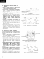
9.3 HORIZONTAL DD OFFSET ADJUSTMENT
1. Remove the bonnet, press the OPEN/CLOSE
key, and pull the slide base forward.
2. Press the manual key for lead-in of the tonearm,
and press the arm elevation key to put the
tonearm in the UP position.
3. Connect a DC voltmeter between the humped
jumpers JP43 and JP44 (see Fig. 9.3).
4. Adjust VRl to obtain a meter reading of t50mV
max.
5. Then press the arm elevation key to lower the
tonearm and check that the tonearm descent is
perpendicular.
Fig. 9,3 HorizontalDD OffsetAdjustment
RED
WHT
BLU
Disconnectleadwires
with solderingiron
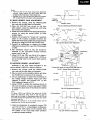
9.4 BAND SENSOR OFFSET ADJUSTMENT
1. Remove the bonnet and P1 and P2 lead wires
indicated in Fig.9.4 (using a soldering iron to
disconnect the lead wires).
2. Using a small screwdriver, turn VR2 and VR3
fully clockwise as seen from above.
3. Connect a DC voltmeter between P2 and PB (TP
terminals) of CN8, and adjust VR4 to obtain a
meter reading of t0.1V max.
Fig. 9.4 Band SensorOffset Adjustment
Nofes.'
* VRz ard VR7 are the band sensorgain djustment
controls. Always djust the band, eensor gain after
completing the band sensoroff*t adjustment.
* Reold,er the Pl and P2 lead wires back into position
after completing the band.sensoroffet adjustment.
9.5 BAND SENSORGAIN ADJUSTMENT
1. Remove the bonnet, press the OPEN/CLOSE
key, and pull the slide base out forwards.
2.Place the GGF-021 test record on the turntable platter, press the manual key, and bring
the tonearm into position.
3. Shade the record surface from strong illumination
sources by using the record jacket or other
suitable shade.
4. Position the tonearm for "locate out" operation
(shift of the tonearm outwards) between the
eighth and tenth tracks ofthe testrecord. Perform
this step by using the STOP and START keys.
5. Connect an oscilloscope to observe the voltage
differences between P2(+) and PB (TP terminals)
of CN8.
6. The waveforms shown in Fig. 9.5 should be
obtained in the inter-track sections between
tracks 8 and 9, and 10.
7. Adjust VR 2 and VRB (see Fig.9.4) to obatin a
waveform peak-to-peakvoltage of.2.6 t 0.2Vp-p,
and an average value in the sound track portion
of t0.1V.
9.6ADDRESS SENSOR ADJUSTMENT
Referring to the time charts described in the
servicemanual (ARP-143), adjust as follows.
1. Remove the bonnet, press the OPEN/CLOSE
key, and pull the slide base out forwards.
2. Place a record on the tumtable platter, and press
the START key for lead-in of the tonearm.
3. Use an oscilloscope to observe the waveforms of
the voltage changes between P12(+) and GND
(address A sensor), and between P13 (+) and
GND (addressB sensor)of IC1.
4. Adjttst VR201 to obtain the waveform shown in
Fig. 9.8, for address A sensor, and adjust V&2O2
to obtain the same kind of waveform for address
B sensor.
Note:
To ad.juat VR2OL and VR202, first switch the PL-88F
power off, disconnect CN3, short Pl ard P2, pull the
slid.e base out by hand (to the position where the VR can
be turned, through the adjustment hole), and then switch
the power bach on.
Wheneuer the tonearm is to be moued, always use the
operation keys. Do not tnoue it by hand.
5. After the adjwtment is completed, connect P12
and P13 of IC1 to a dualdisplay oscilloscope,
and proceed with lead-in of the tonearm from
the spindle to the outer edge (start operation
or manual tonearm setting).
2. 6 t 0 . 2 V
Tonearm
locateout
Fig. 9.5 Oscilloscope
WaveformDisplay
ov
f@,^,
;i+*
f@,*
Fig. 9.6 BandSensorGainAdjustment
Adjustment
hole
Switch the power off and pull the slide baseout.
Fig. 9.7 AddressSensorAdjustment
tc1P12
lcl Pl3
a, b,c, d= I 2msec
Fig. 9.8 Oscilloscope
Waveform
Finalwaveform
v R 2 0|
vRzoz
/
rum
N
r/
\s,t",
Fig. 9.9 WaveformAdjustment
25
6. Check that the P13 waveform is ahead of the
P12 as indicated in Fig. 9.8, and that a, b, c,
and d in this diagram are all greater than l2msec.
The tonearm must always move from the spindle
towards the outer edge of the record. If it moves
towards the center of the record, the P12 waveform should be atread of the P13 waveform.
Leadwire l C l p i n Adjustment control
Address
A sensorc N 2 P 1 6
P12
vR202
AddressB sensor cN2 P14
Pl3
VR201
9.7 HORIZONTAL DD CANCEL ADJUSTMENT
1. Remove the bonnet, press the START key, and
switch the power off when the tonearm comes
close to the lowering position for 30cm records.
The tonearm remains elevated in this case.
2. Connect an oscillator to P9 and P10 in the
socket side of the CN 2 connector, connect an
oscilloscope to P11 and P12, and short P10 to
P11.
3. Generate a 10Vp-p 45OHz sine wave signal in
the oscillator, and check that a 450H2 sine wave
slgral is displayed in the oscillocope.
4. Adjust VR203 to obtain a 120mVp-p (t10mV)
waveform signal in the oscillocope.
5. Move the tonearm slowly by hand towards the
center of the record. As the tonearm is moved
towards the center from the 30cm lowering
position, the waveform amplitude is gradually
decreased, reaching a minimum at a point a
little before the spindle. Moving the tonearm
any further inwards results in the amplitude
increasing Eatn.
6. Set the tonearm in the position where minimum
amplitude was achieved, and readjust VR203 to
obtain an amplitude of less than 2OmVp-p
(approx). (SeeFig. 9.11).
9.8 STYLUS HEIGHT ADJUSTMENT
1. Remove the bonnet and switch the power on.
Press the OPEN/CLOSE key and pull the slide
base out forwards.
2.Place a record on the tr:rntable platter and press
the MANUAL button to move the tonearm
forward.
3. While holding the tonearm in the left hand,
adjust the adjustment screw with a wrench
(1.5mm) passed through the adjustment hole as
shown in Fig. 9.12.
4. Adjust the stylus tip to a height 5 to ?mm above
the record.
Fig. 9.10 HorizontalDD CancelAdiustment
n
/
\
n
V
/
\
n---f\
/
30cmlowerins
Position
| 12omV
Final point
20mV max.
Fig. 9.11 AdjustmentWaveform
Wrench(1.5mm)
Height adjustmentscrew
Fig. 9.12 StylusTip adjustmentScrew
26
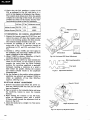
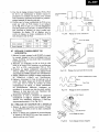
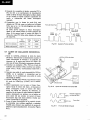
9.9 MOTOR OPERATION POINT ADJUSTMENT
1. Open the slide base as described in "Dummy
Play Mode Setting", and run the motor at 33-1/
3rpm.
2. Connect the buffer amplifier shown in Fig.9.14
to the 3P connector from the motor base plate,
and connect the output to a oscilloscope
(making the lead wire length less than 10cm to
reduce the effects of extraneous electrical noise).
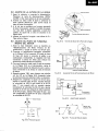
3. With a waveform like that shown in Fig. 9.15 in
the synchroscope, vary the gain to adjust the
peak-to-peak distance in the sawtooth waveform
to five divisions.
4. Then adjust VRl to obtain an a:b ratio of 3:2 in
Frg. 9.15 (taking every precaution to eliminate
unwanted noise).
5. After completing the 33-U3rpm adjustment,
repeat the process for 45rpm. Always adjust the
33-U3rpm speed before the 45rpm speed. And
even if only the 33-U3 rpm speed initially needs
adjustment, also adjust the 45rpm speed after
the 33-1/3rpm adjustment. Adjust VR2 for
45rpm. After completing the 45rpm adjustment,
check the 33-1/3rpm speed.
D
Motor
3P connect
Slidebasecover
Fig. 9-13 Motor OperationPoint Adjustment
F i g .9 . 1 4 B u f f e rA m p l i f i e r
IS m s e c ( 3 3 )
l3.3msec(45)
Fig. 9.15 AdjustmentWaveform
s",ewdriver
Itil__
\
, lli
\ry0 l
\l
I I
tot
AI
\
\\-
q>-vR1
C-vnz
F i g .9 . 1 6 A d j u s t m e n P
t oint
?7
(GGF.O2l)
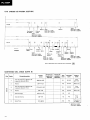
9 . 1 O T E S TR E C O R D S
@
t
Frequenry
700H2
t
Count
1
I
Count
Lch; English
Rch; Spanish
Count
Lch; English
Rch;Spanish
Unrecorded
tracK
Music
Lch; English
Rch; Spanish
@
@il @
.J",
I
Forward feed
Courit
@
o
oll
1
Unrecorded Count
track
Lch; English
Lch; English
Rch; Spanish
o
@
@tl @
Rch; Spanish
+ Portion to
be detectd
Count
Lch; English
Rch; Spanish
Unrecorded Count
3kHz
track
Lch; English
Rch;Spanish
as an interval between music t rcts
i fi
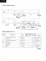
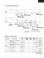
RECORDCONTENTS(SIDE B}
Side
Band
Recording contents
Size
(@mm)
Recording Recording
l€v6l
time
(cm/secl
(sec)
Pitcfl
(mml
Speed
(rpml
Remarks
29atO.2 - 2a7
0.1
3 3 1 / 3 Count301- 55
287 - 173.3
4.0
3 3 1 / 3 M u s i c( 1 )
1 7 3 . 3 t 0 . 2- 1 6 3
0.1
3 3 1 / 3 C o u n t1 7 1 - 5 0
1 6 3- 1 4 0
4.O
3 3 1 / 3 Music(2)
1 4 0 r 0 . 2- 1 3 3
1.0
45
Returncount
1 3 3- 1 0 7
1.0
45
Count 1 - ' 1 2
Lead-out
107-e6
1l
4.O
45
Frequency
7 O OH z
1
30cmstylusloweringpositioncount
2
Forward feed
3
17cm stylus lowering position count
4
Forward feed
(D
track
Unrecorded
5
6
*
..4 O
Lch; English
Rch; Spanish
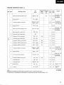
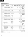
RECORDCONTENTS(SIDE A)
Side
Band
Recording contents
30cm stylus lowering position count
Size
(@mm)
Recording Recording
lsv6l
time
(cm/secl
(secl
298tO.2 - 287
99
Pitch
(mml
0.1
1
Stereo music (1)
2
Frequency3,000 Hz (horizontal)
3
Stereo music
l2l
25cm stylus lowering position count
287 - 258.5
Speed
(rpml
Count301 - 55
3 3 1 / 3 Lch; English
Rch;Spanish
33 1/3
258.5!02 - 257.5
257.5 - 257.3
0.5
0.1
257.3 - 249
331/3
247.1!O.2- 239
0.1
Count251 - 50
3 3 1 1 3 Lch; English
Rch;Spanish
Stereo music (3) - cocentricity
239 - 226
331/3
5
U n r e c o r d e dt r a c k ( c o c e n t r i c i t y )
225
33 1/3
o
F r e q u e n c y3 1 5 H z ( h o r i z o n t a l )
224 - 216
7
U nrecorded track (cocentricity)
216 - 2OG
8
0.1
3 31 1 3
331/s
3.54
0.1
33 1/3
F r e q u e n c y1 , 0 0 0 H z ( r i g h t c h a n n e l )
2O1.2 - 196.4
3.54
0.1
33113
Frequency1,000Hz (horizontal)
1 9 6 . 4- 1 8 5 . 8
5.0
0 . 1 33 1 t 3
o
Frequency 3,000 Hz (horizontal)
10
Stereo music (4)
't'l
5.42
206 - 2O'1.2
Frequency 1,0O0Hz (left channel)
17cm stylus lowering position
Turn the rec o r d i n g l e v e lt o
m i n . ( o n et u r n )
331/3
4
6
Remarks
Turn the re-
1 8 5 . 8 t 0 . 2- 1 8 4 . 8
144.4 - 184.6
0.5
3 3 1 / 3 cordinglevelto
o.1
m i n . ( o n et u r n )
1 8 4 . 6- 17 5 . 3
33 1 1 3
173.3t0.2 - 163
u-l
C o u n t1 7 1 - 5 C
3 3 1 / 3 Lch; English
Rch;Spanish
0.1
331/3
Frequency3,00O Hz (horizontal)
r 6 1 145
Unrecorded
track
145 - 14O
Unrecorded track
14OxO.2- 133
1.0
45
1 3 3- 1 0 7
1.0
45
107- e6ll
4.O
45
5.0
12
0.1 33 1/3
13
Returncount
14
Lead-out
Note:
Sizesgiuen in this list are general ualuea (but limits must be ouserued where giuen).
Tle inner/outer circumference 0,5mm pitch for concentricity in band 5 must lie within t0.05.
C o u n t1 - 1 2
Frequency
7 O OH z
Lch; English
Rch; Spanish
29
9. REGLAGE
Ajustement de Mode de Lecture Fictive
Le PL-88F peut 6tre mis en mode de lecture
fictive (en mode "loading out") de la manidre
suivante.
1. Enlever le capot et mettre en mode "loading
out".
2. Couper le courant.
3. D6brancher la fiche CNB sur le assembl6e de
contr6le et mettre un cavalier de I'ergot 1 d
l'ergol,2.
4. Puis, mettre sous tension, mettant ainsi le
tournedisquesen mode de lecture.
Remarques:
1. Pour utiliser ce systdme (capot enleud, mode "loadingout") dans les opdrations de s<ilection de sillon et de
rdglage, s'assurer que la section de cartouche de bras
de pick-up est protdgi de toute lumidre extdrieure.
2. Pour udrifier les opirations relatiues d l'adrexe (y
compris les opdrations pendant la sdlection de sillon
et la lecture) ne pas manipuler le bras de pick-up ri
la main. Se seruir des cl6s d'opdration.
3. Ne pas toucher d la cld OPEN/CLOSE.
4. Toujours s'assurer que l'alimentation est coupde pour
brancher ou ddbrancher les fiches.
R69lages
Diff6rentes m6thodes sont utilis6es pour r6gler
la position d'abaissement de l'aiguille pour le
premier sillon ou pour les autres sillons dans les
op6rations automatiques de lecture du PL-88F.
La position d'abaissement pour le premier sillon
est r6gl6e selon "R6glage de I'emplacement d'abaissement de l'aiguille", tandis que le ftglage pour les
autres sillons se fait selon "R6glage de I'emplacement d'abaissement de I'aiguille entre les pistes".
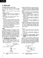
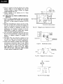
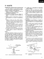
9.1 REGLAGE DE L'EMPLACEMENT
D ' A B A I S S E M E N TD E L ' A I G U I L L E
1. Presserla cl6 OPEN/CLOSE, tirer la basecoulissante vers I'avant, mettre un disque sur le
plateau et positionner le s6lecteur de vitesse
sur le nb. de tpm. correct.
" a/
F i g .9 - 1
30
2. Presserla cl6 START pour commencer lalecture.
V6rifier la direction et le degr6 de d6placement
de I'aiguille i ce moment. (Estimer la distance
en mm. de l'6loignement de I'aiguille du premier
sillon.)
3. Selon la direction et le degr6 de d6placement,
r6gler la vis de r6glage avec un petit tournevis
comme il est indiqu6 Fig. 9-1.
* Tourner la vis vers la droite (en regardant du
dessus) si I'aiguille s'abaisse i I'int6rieur du
premier sillon.
x Toumer la vis vers la gauche (en regardant du
dessus) si l'aiguille s'abaisse d I'ext6rieur du
premier sillon.
x Un demi tour de la vis correspond i un
d6placement de la position d'abaissementde
9mm environ.
4. Lorsque le disque d'essai PLS-2001S est utilis6,
r6gler la vis pour obtenir une lecture entre 305
et 317 pour l'abaissement sur un disque de 30
cm. Pour le disque d'essai GGF-021, r6gler
pour obtenir une lecture entre 3 et 30 pour un
disque de 30cm.
Remarques:
* Enleuer le capot
de cas, le rdglage
d blason.
* Ne pas incliner
pas appuyer trop
dant l'opdration.
facilite l'opdration de rdglage. Dans
s'opire par le haut, sous le couvercle
le tourne-disques exag6r6ment, ne
fortement sur la uis de rdglage pen-
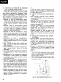
9.2 REGLAGE DE L'EMPLACEMENT D'ABAISS E M E N TD E L ' A I G U I L L E E N T R E L E S
PISTES
Se servir de cette m6thode de r6glage lorsque
I'aiguille ne descend pas correctement en position
entre les pistes au cours d'une lecture de programme normal (lorsque le commutateur de sensibilit6
est en position NORMAL et qu'an disque ordinaire
est utilisd.) Cette position dewait 6galement 6tre
ftgl6e aprds remplacement de I'aiguille.
Orifice de riglage
ldanslaPlaque de base).
R 6 g l a gdee l ' e m p l a c e m e nd t' a b a i s s e m ednet
| ' ai g ui ll e
Fig.9-2
Rdglage
de l'emplacement
d'abaissement
de
l ' a i g u i l l ee n t r el e sp i s t e s
1. Presserla cl6 OPEN/CLOSE, tirer la basecoulissante vers I'avant, placer un disque de 30cm sur
le plateau et positionner le s6lecteur de vitesse
sur le nombre de tpm. correct.
2. Presser la cl6 START et continuer en mode de
lecture de programme ( i I'exclusion du premier
sillon du progumrme). Estimer la direction et le
degr6 de d6placement i ce moment.
3. Presser la cl6 OPEN/CLOSE et tirer la base
coulissante vers l'avant. Puis presser la cl6
MANUAL et d6placer le bras de pick-up vers
I'avant.
4. Selon le degr6 de d6placement, r6gler la vis de
r6glage dans la coquille de t6te d I'aide d'un petit
tournevis. (Voir Fig. 9-2)
o Tourner la vis de r6glage vers la droite si I'aiguille
s'abaisse d I'ext6rieur des sillons programm6s.
o Tourner la vis de r6glage vers la gauche si l'aiguille
s'abaisse i I'int6rieur des sillons programm6s.
o Un tour complet de la vis correspond i un d6placement de 0,2mm de la position d'abaissement.
5. Recommencer la lecture d'un programme (i I'exclusion des premiers sillons du programme), et
v6rifier que I'aiguilles s'abaisse conectement
entre les pistes.
6. Lorsque le disque d'essai GGF-021 est utilis6,
positionner le commutateur de sensibilit6 sur la
position HIGH, puis r6gler la vis pour obtenir
un signal de sortie de lkHz pendant B ou 4
secondes, temps n6cessaire pour que I'aiguille
s'abaisse sur la deuxidme piste du disque GGF-
4. R6gler VRl pour obtenir une lecture de voltmdtre DC de t50mV ma:<imum.
5. Puis, presser la cl6 d'6l6vation de bras de pick-up
et v6rifier qu'il descend perpendiculairement.
9.4 REGLAGE D'ECART DE SONDE DE
BANDE
1. Enlever le capot et les fils de plomb PL et P2
indiqu6s dans Ia Fig. 9-4 (au moyen d'un fer i
souder pour les d6tacher).
2. Au moyen d'un petit tournevis tourner VR2 et
VR3 compldtement vers la droite (en regardant
du dessus).
3. Brancher un voltmdtre DC entre P2 et PB
(bornes TP) de CN8, and r6gler VR4 pour
obtenir une lecture maximum de t0.1V.
Remarques:
* VR2 et VRS sont les rdglages de contr6le du gain des
sondes de bandes. Rdgler toujours le gain de la sonde
de bandes aprds auoir terrnind le rdglage d'dcart de
sonde de bandes.
* Resoud,er les fils de PI et P2 dans leur position aprAs
auoir effectud le rdglage de d,dcalagede sond.e d.e bande.
o21.
7. Aprds avoir termin6 le r6glage, continuer la
lecture du programme et v6rifier que la sortie
de Ll<llz est bien obtenue pendant B ou 4
secondespour les pistes qui suivent la premidre
piste, et que lkHz est 6galement obtenu aprds
la sixidme piste.
Fig. 9-3
Remarque:
Si une position d'abaissement ne pouuait pas €tre obtenue
au moyen de cette mdthode, ou si l'abaissement de
I'aiguille nbst pas assuri, continuer au moyen d,u "Rdglage
d'6cart DD horizontal"
puis renouveler le rdglage cidessus.
9.3 NECUCC
R6glage
d'6cartDD horizontal
D d b r a n c h e rl e s f i l d e p l o m b d
l'aide d'un fer d souder
D'ECANT DD HORIZONTAL
1. Enlever le capot, presserla cl6 OPEN/CLOSE et
tirer la base coulissante vers I'avant.
2. Presser la cl6 manuelle de conduite du bras de
pick-up, presser la cl6 d'6l6vation du bras de
pick-up pour le mettre en position haute.
3. Brancher un voltmdtre DC entre les coupleurs
bossusn $ et JP 44 (Voir Fig. 9-B)
Fig. 9-4
R6glaged'6cart de sonde de bande
31
9.5 REGLAGE DE GAIN DE SONDE DE
BANDES
1. Enlever le capot, presser la cl6 OPEN/CLOSE
et tirer la basecoulissantevers I'avant.
2.Placer le disque d'essai GGF-021 sur le plateau,
presser la cl6 MANUAL et mettre le bras de
pick-up en position.
3. Emp6cher tout forte illumination d'atteindre
le disque en le prot6geant au moyen de l'enveloppe du disque, par exemple.
4. Positionner le bras pour op6ration de recherche
(d6placement du bras vers I'ext6rieur) entre les
huitidme et dixidme pistes du disque d'essai.
Arriver d ce r6sultat au moyen des cl6s STOP
et START.
5. Brancher un oscilloscope pour observer les
diff6rences de voltage entre P2 (+) et P3 (bornes
TP) de CNS.
6. La forme ondulatoire montr6e dans la Fig. 9-5
doit 6tre obtenue dans les sections entre les
pistes 8 et 9, et 10.
7. R6gler VR2 et VR3 (Voir Fig. 9-4) pour obtenir
une forme ondulatoire avec un voltage de 2,6
tO,2Vp-p de sommet i sommet, ainsi qu'une
valeur moyenne de t0,1V dans les portions de
pistes sonores.
9.6 REGLAGE DE SONDE ADRESSEE
Tout en se r6f6rant au tableau du temps du manuel
de service (ARP-143), r6gler de la fagon d6crite
ci-dessous.
1. Enlever le capot, presserla cl6 OPEN/CLOSE et
tirer la basecoulissantevers l'avant.
2. Placer un disque sur le plateau et presser la cl6
START pour conduite du bras de pick-up.
3. Se servir d'un oscilloscope pour observer la
forme ondulatoire des changements de voltage
entre P12 (+) et GND (Sonde A adress6e),et
entre P13 (+) et GND (Sonde B adress6e)de
IC1.
4. R6gler VR201 pour obtenir la forme ondulatoire
montr6e dans Ia Fig. 9-8 pour la sonde A
adress6e.R6gler VP"2O2 pour obtenir la m6me
forme ondulatoire pour la sonde B adress6e.
Remarque:
Pour r6gler VR201 et VR202, commencer par couper Ie
courant du PL-88F. ddbrancher CNS. court-circuiter Pl
et P2, tirer la base coulissante d la main (en une position
telle que les VR puissent 6tre tournds d trauers les trous
de r6glage), puis remettre le courant.
Chaque fois que le bras de pich-up d.oit 6tre ddplacd, se
seruir des cl6s de commandes. Ne pas le ddplacer d la main.
2,6!0,2V
R e c h e r c h ev e r s l ' e x t d r i e u r
d u b r a sd e p i c k - u p
Entre lespistes
Indication de forme ondulatoire de l'oscilloscope
Fig. 9-5
ov
vR2@
n
tL\-ov
--"-.\.\
u"t fZ\
@
Fig. 9-6
f@u"s
;nn*-
*.A--{-@,^,
R 6 g l a g ed e g a i n d e s o n d e d e b a n d e
Orif ice de 169lage
Orif ice de 169lage
* C o u p e r l e c o u r a n t e t t i r e r l a b a s ec o u l i s s a n t ea u d e h o r s .
Fig. 9-7
R 6 g l a g ed e s o n d e d ' a d r e s s e
tc't P12
tc1 P13
a . v . c . d ) 12 m s e c .
Fig.9-8
F o r m e o n d u l a t o i r ed e I ' o s c i l l o s c o p e
5. Une fois le r6glagetermin6, brancher P12 et P13
de ICl d un oscilloscope d double voyant et
poursuivre la conduite du bras du pivot central
vers I'ext6rieur (op6ration de d6part ou positionnement manuel du bras de pick-up).
6. V6rifier que la forme ondulatoire de P13 est en
avant sut celle de PL2 comme il est indiqu6
sur la Fig. 9-8, et que a, b, c et d du diagramme
sont plus grands que 12 msec. Le bras de pick-up
doit toujours se d6placer du pivot central vers
I'ext6rieur du disque. S'il se d6place vers le
centre du disque, la forme ondulatoire de P12
doit devancercelle de P13.
Fil de plomb
Ergot
rc1
Contr6le de
16glage
Sonde A adress6e
cN2 P16
P12
vR202
Sonde B adressde
cN2 P14
P13
VB201
9.7 REGLAGE D'ANNULEMENT DD
HORIZONTAL
1. Enlever le capot, presserla cl6 START et couper
le courant lorsque le bras va s'abaisserpour un
disque de 30cm. Le bras doit rester en position
haute dans ce cas.
2. Brancher un oscillateur sur P9 et P10 du c6t6
prise de la bome CN2, brancher un oscilloscope
sur P11 et P72, court-circuiter P10 et P11.
un signal ondulatoire sinusoidal de
Produire
3.
10Vp-p 450H2, et s'assuretqu'un signal d'onde
sinusoidale de 450H2 apparait sur l'oscilloscope.
4. R6gler VR203 pour obtenir un signalondulatoire
de 120mVp-p (t1OmV) sur l'oscilloscope.
5. D6placer doucement le bras de pick-up vers le
centre. En m6me temps que le bras est d6plac6
d la main vers le centre en partant du point
d'abaissement de 30cm, la forme ondulatoire
est graduellement diminu6e, atteignant un
minimum i un point non loin du pivot central.
D6placer le bras plus loin vers I'int6rieur fait
accoroitre I'amplitude i nouveau.
6. Positionner le bras i I'endroit de minimum
d'amplitude et r6gler i nouveau VR203 pour
obtenir une amplitude inf6rieure i 20mVp-p
(approximativement). (Voir Fig. 9-11)
9.8 REGLAGE DE HAUTEUR DE L'AIGUILLE
1. Enlever le capot et mettre sous tension. Presser
la cl6 OPEN/CLOSE et tirer la base coulissante
vers I'avant.
2. Placer un disque sur le plateau du tourne-disques
et presserla cl6 MANUAL pour faire avancer le
bras de pick-up vers l'avant.
Forme ondulatoire
fi nale
VR2OI ,q1\ /
vR202 \\v ./
mm
Fig.9-9
\ \ ... u"'o'
\)y vR202
R d g l a g ed e f o r m e o n d u l a t o i r e
DtD h o r i z o n t a l
F i g . 9 - 1 0 R 6 g l a gde' a n n u l e m e n
P o s i t i o n d ' a b a i s s e m e n st u r 3 0 c m
Point final
20mV max.
F i g .9 - 11
R 6 g l a gdee f o r m e o n d u l a t o i r e
Cld (1,5mm)
Vis de rdglagede hauteur
F i g . 9 - 1 2 V i s d e 1 6 9 l a gdee b o u t d ' a i g u i l l e
33
3. Tout en tenant le bras de pick-up de la main
gauche, r6gler la vis de r6glage avec une cl6
(1,5mm) pass6e i travers l'orifice de r6glage
comme indiqu6 Fig. 9-12.
4. R6gler I'aiguille i une hauteur de 5 i 7mm
au-dessusdu disque.
9 . 9 R E G L A G E D U P O I N T D ' O P E R A T I O ND U
MOTEUR
1. Ouvrir la base coulissante ainsi qu'il est d6crit
dans "AJUSTMENT DE MODE DE LECTURE
FICTM"
et faire toumer le moteur e 33-1/3
tpm.
2. Brancher I'amplificateur tampon montrr5 en Fig.
9-14 sur la borne 3P i la base de la plaque de
moteur, et brancher la bome 3P d la base de la
plaque de moteur, et brancher la sortie i un
oscilloscope (en limitant la longeur du fil de
branchement d moins de 10cm pour r6duire
l'effet des bruits 6lectriques ext6rieurs).
3. Avec une forme ondulatoire telle que celle de la
Fig. 9-15 du synchroscope, changer le gain pour
amener la distance sommet i sommet d 5
divisions.
4. Puis r6gler VR1 pour obtenir un rapport a:b de
3:2 dans la Fig. 9-15 (en prenant toute pr6caution pour 6liminer les bruits ind6sirables).
5. Aprds avoir termin6 le r6glagepour 33-1/3 tpm,
recommencer l'op6ration pour 45 tpm. R6gler
toujours 33-Ug tpm avant 45 tpm. Et m6me si
la vitesse 33-Ug a seule besoin d'6tre r6gl6e,
r6gler 6galement la vitesse de 45 tpm. R6gler
VR2 pour 45 tpm aprds avoir 16916la vitesse
45 tpm, v6rifier la vitesse33-1/3 tpm.
B r a n c h e m e n t3 P
Baseflottante
Couverture de la base coulissante
R6glage
du point d'opdrationdu moteur
Fig. 9-13
Branchement
Fig.9-14 Amplificateurtampon
SDIV
F i g .9 - 1 5
R d g l a gdee f o r m e o n d u l a t o i r e
II
I'f-Tournevis
|\Y \11
fr
\|----I
'-
- - - - - . } ^ | l |
/
/
h
" L - - r - \l ll
li
$)-vnt
t r_vR2
\l
1l
Fis.e-1; ,1,n,,o. r6srage
34
9.10 DTSOUES
D'ESSA!(ccF-021)
@
I
Fr6quence
700H2
ttt
?
compte
t
Canal de gauche; Anglais
Canal de droite; Espagnol
Musique
pisienon I
Compte
Canalde gauche;Anglais
enreoistrde
I
canal de droite; Espagnol
ruusique
Canal de gauche; Anglais
Canal de droite; Espagnol
@
@tl @
@
o @ll
@
rt
ilt
| 3kHz I
31sHz
I
I
P i s t en o n
en registrde
Compte
Canal de gauche; Anglais
Canal de droite; Espagnol
I
rrr,lrior"
st6r6o
Musique
Compte
M u s i q u e st6r6o
Canal de gauche; Anglais
stdreo
Canal de droite; EspCgnol
Compte
C a n a l d e g a u c h e ;A n g l a i s
Canal de droite; Espagnol
Plage d d6tecter
p i s t e sm u s i c a l e s .
comme
intervale entre deux
{r
M E T T E R ED U D T S O U E( C 6 t 6B )
cot6
@
ro
€
Bande
MatiCre enregistr5e
1
Compte de position d'abaissement de
l ' a i g u i l l es u r 3 0 c m .
2
Alimentation vers l'avant.
3
C o m p t e d e p o s i t i o n d ' a b a i s s e m e n td e
l ' a i g u i l l es u r 1 7 c m .
4
Alimentation vers l'avant.
Dimension
lomml
Niveaud'en- Temps d'en- Haut€ur
Vitess€
rogistr€ment roglstrem€nt de son
(tpml
(cm/secl
(soc)
(mm)
Remarques
Compte de
298!0.5-287
0,1
33 1/3
287-173,3
4,O
331/3
M u s i q u e( 1)
173,3tO,2-163
0,1
331/3
Comptede
1 7 1a 5 0
163-140
4,O
3 31 1 3
Musique (2)
140t0,2-133
1,0
45
133-107
1,0
45
Compte de
'l
it 12
1o7-e613
4,O
45
Fr6quence
700H2
301e 55
o
Pistenon enregistr6e.
5
compte de retour.
o
Conduite vers l'extdrieur.
*
*
C a n a l d e g a u c h e ;A n g l a i s
Canal de droite; Espagnol
M E T I E R E SD U D I S O U E( C 6 t 6A )
c616
Bande
I
MatiCre enregistr6e
Compte de position d'abaissement
d e l ' a i g u i l l ed 3 0 c m .
M u s i q u es t d r 6 o ( 1 )
2
F r d q u e n c e3 , 0 O O H z( h o r i z o n t a l) .
2
Musiquestdr6o(2)
Dimension
(4rmm)
Niveaud'en- Tempad'en- Hauteur
Vitosse
registrement registroment de son
(tpml
(cm/secl
(mml
(secl
298!0,2-287
99
331/3
0.1
2A7-258.5
0,5
o,1
331/3
257.3-249
247,'l!0,2-239
Musiquestdrdo (3) -concentricit6.
239-226
€
€
o
P i s t e n o n e n r e g i s t r 6 e( c o n c e n t r i c i t d ) .
b
F r d q u e n c e3 1 5 H z ( h o r i z o n t a l ) .
224-216
7
P i s t e n o n e n r e g i s t r 6 e( c o n c e n t r i c i t 6 ) .
216-206
8
F r 6 q u e n c e 1 , O O O H z( c a n a l d e g a u c h e ) .
F r 6 q u e n c e1 , 0 0 0 H 2 ( c a n a l d e d r o i t e ) .
F r d q u e n c e 1 , O O O H z( h o r i z o n t a l ) .
206-201 ,2
201,2-196,4
196,4-185,8
9
F r d q u e n c e3 , 0 0 0 H 2 ( h o r i z o n t a l ) .
185,8r0,2
-184,8
184,8-184,6
10
Musiquest6r6o (4).
1U,6-175,3
1l
P o s i t i o n d ' a b a i s s e m e n td e I ' a i q u i l l e
d 17cm.
173,3!O,2
-163
F r 6 q u e n c e3 , 0 0 0 H 2 ( h o r i z o n t a l) .
161-145
P i s t en o n e n r e g i s t r d e .
Piste non enregistrde.
B a i s s e rl e n i v e a u
d'enregistrement au minimum (1 tour).
331/3
0.1
33 113
4
5
Compte de
301 a 55
Canal de gauche;
Anglais
Canal de droite;
Espagnol
33 1/3
258,5tQ,2
-257,5
257,5-257,3
Compte de position d'abaissement
d e l ' a i g u i l l ed 2 5 c m .
Remarques
Compte de
251 d 50
Canal de gauche;
Anglais
Canal de droite;
Espagnol
331/3
331/3
225
5,42
0,1
33 1/3
33 1/3
3,54
3,54
5,0
331/3
331t3
33 1/3
0,1
0,1
0,1
0,5
0,1
33 1/3
B a i s s e rl e n i v e a u
d'enregistrement au minimum (1 tour).
33 1/3
Compte de
171d 50
Canal de gauche;
Anglais
Canal de droite;
Espagnol
0,1
331/3
0,1
331/3
145-140
0,1
33 1/3
1 4 0j 0 . 2 - 1 3 3
1,0
45
compte de retour.
133-107
1,0
45
Compte de
't
d12
Conduite vers l'ext6rieur.
107-e613
4,O
45
Fr6quence
TOOHz
5,0
12
l3
'14
*
Canal de gauche; Anglais
Canal de droite; Espagnol
Remarques:
Les mesures donn6es dans cette liste sont des ualeurs g'ndrales (mais les limites doiuent 6tre obserudes quand elles
sont
donndes.)
La circonf6rence int(irieure'extdrieure de 0,5mm niueau de son pour concentricitd d.e la bande S doit se trouuer dans +0.05.
36
9. AJUSTE
Establecimientodel Modo Ficticio de Roproducci6n
Se puede establecer el modo ficticio de reproducci6n (en el modo de "disposici6n de colocaci6n
del disco") mediante el m6todo siguiente.
l-. Extraer la cubierta y establecer el modo de
"disposici6n de colocaci6n del disco".
2. Desconectarla alimentaci6n.
3. Desconectar el conector CN3 del conjunto de
control y cortocircuitar entre las patillas (1)
v Q).
4. Despu6s conectar la alimentaci6n, poniendo el
girael giradiscos en el modo de reproducci6n.
Nota:
1. Cuando se utilice este modo (cubierta sacada y
disposici6n d,e colocaci6n del disco) para operaciones
de selecci6n de pista y ajustes, asegurarse de que la
secci6n de la cdpsula del brazo fonocaptor estd protegida contra Ia luz extrafia.
2. Al comprobar las operaciones relatiuas a la direcci6n
(que incluyan operaciones durante la selecci6n de
pista y reproducci6n), NO tocar con la mano el brazo
fonocaptor. Cuando haya que utilizar el brazo fonocaptor, usar las teclas de operaci6n.
3. NO utilizar la tecla abertura/cierre
OPEN/CLOSE.
4. Asegurarse siempre de que la alimOntaci6n estd desconectada cuando se conecten o desconecten los
desconectores.
Ajustes
Se utilizan diferentes m6todos para ajustar la
posici6n de descenso de la aguja para pista 1 para
las otras pistas para operaci6n de reproducci6n
autom6tica del PL-88F. La posici6n de descenso
para pista 1 se ajusta de acuerdo a n'Ajuste de la
Posici6n de Descenso de la Aguja", mientras que
la posici6n de descenso para otras pistas se ajusta
de acuerdo a "Ajuste de la Posici6n de Descenso
de la Aguja entre Pistas".
9.1 AJUSTE DE LA POSICION DE DESCENSO
DE LA AGUJA
1. Presionar la tecla de abertura/ciene OPEN/
CLOSE, tirar hacia afuera de la base deslizable,
colocar un disco de 30cm sobre el plato y poner
las rpm conectas mediante el selector de velocidad.
2. Presionar la tecla de inicio START para comenzat la reproducci6n. Comprobar al mismo tiempo la direcci6n y el grado de desplazamiento de
la aguja. (Estimar la distancia aproximada que
hay en mm desde la aguja hasta el surco inicial
del disco).
3. Dependiendo de la direcci6n y el grado de
desplazamiento ajustar el tornillo de ajuste indi
cado en la Figura 9-1 con un pequeflo destorniIlador.
* Girar el tornillo hacia la derecha (visto desde
arriba) si la aguja desciende hacia el exterior
del surco inicial del disco.
* Girar el tornillo hacia la izquierda (visto desde arriba) si la aguja desciende hacia el interior del surco inicial del disco.
x Una media vuelta del tomillo corresponde a un
desplazamiento de aproximadamente de 9mm en
la posici6n de descenso.
4. Cuando se utilice el disco de prueba PLS-2001S,
ajustar el tornillo para obtener un valor comprendido entre 305 a 3L7 de descensosobre un
disco de 30cm. Y si se utiliza el disco de prueba
GGF-021, ajustar a un valor comprendido
entre 6 y 30 para un disco de 30cm.
Nota:
* La extracci6n de la cubierta simplifica las operaciones
de ajuste. En este caso, se pueden realizar los ajustes
desde Ia parte superior de Ia cubierta ornarnental.
* No inclinar demasiado el giradiscos ni aplicar excesiva
presiSn al ajustar el tornillo durante la operaci6n de
ajuste.
Orificio de Ajuste
((en
en la placade base)
.
//./
Trasera
Tornillo de ajuste
Fig 9-2
Fig. 9-1
Ajustede la posici6nde descenso
de la Aguja
Ajustede la Posici6nde Descenso
de la Aguja
entre Pistas
9.2 AJUSTE DE LA POSICIoN DE DESCENSO
DE LA AGUJA ENTRE PISTAS
Utilizar este m6todo de ajuste cuando la aguja
no desciende conectamente a la posici6n entre las
pistas durante reproducci6n programada normal
(cuando el conmutador de sensibilidad est6 en la
posici6n normal NORM y se est6 utilizando un
disco ordinario). Esta posici6n tambi6n se debe
ajustar cadavez que se sustituya la aguja.
1. Presionar la tecla de abertura/cierre OPEN/
CLOSE, tirar hacia afuera de la base deslizable,
colocar un disco de 30cm sobre el plato y ajustar
las rpm correctas mediante el selector de velocidad.
2. Presionar la tecla de inicio START y pasar al
modo de reproducci6n programada (excluyendo
la primera pista del programa). Estimar la
direcci6n y el grado de desplazamiento al mismo
tiempo en la posici6n de descenso.
3. Presionar la tecla de apertura/cierre OPEN/
CLOSE y tirar hacia afuera de la base deslizable. Despu6s presionar la tecla de reproducci6n manual y mover el brazo fonocaptor hacia
el disco.
4. Dependiendo del grado de desplazamiento,
ajustar el tornillo de ajuste del casco de la
c6psula (consultar Figura 9-2) con un pequeflo
destornillador.
o Girar el tornillo de ajuste hacia la derecha si la
aguja desciende en la pista hacia el exterior de la
pista programada.
r Girar el tornillo de ajuste hacia la izquierda si la
aguja desciende hacia el interior de la pista
programada.
o Una vuelta completa del tornillo corresponde a
un desplazamiento de 0,2mm en la posici6n de
descenso.
5. Proceder otra vez con reproducci6n programada
(excluyendo la pista primera del progmma)
y comprobar que la aguja desciende conectamente entre las pistas.
6. Al ajustarse con el disco de prueba GGF-021,
poner el conmutador de sensibilidad en la
posici6n alta HIGH y despu6sajustar el tomillo
para obtener la sefral de salida de lkHz durante
tres o cuatro segundospara pistas despu6sde la
pista primera y esa misma sefral de lkHz se
obtiene tambi6n para pistas despu6s de la pista
sexta.
7. Despu6s de sinalizar el ajuste, activar la reproducci6n programada y comprobar si se obtiene
seflal de solida de lkHz durante tres o cuetro
segundo en pistas posteriores a la primera y
tambi6n. a la sexta.
Nofo;
Si no se puede obtener la posici6n de descenso correcta
mediante este mdtodo de ajuste, o si la posici6n de descenso de la aguja no es permanente, efectuar el "ajuste
de equilibrio Horizontal DD".
9.3 AJUSTE DE EOUILIBRIO HORIZONTAL
DD
1. Sacar la cubierta, presionar la tecla de abertura/
cierre OPEN/CLOSE y tirar hacia afuera de la
basedeslizable.
2. Presionar la tecla manual para llevar el brazo
fonocaptor al disco y presionar la tecla de
elevaci6n del brazo para poner el brazo fonocaptor en la posici6n UP.
3. Conectar un voltfmetro de CC entre los puentes
salientes JP43 y JP44 (consultar Figura 9-3).
4. Ajustar VR1 para obtener una lectura en el
medidor de t50mV m6ximos.
5. Despu6s presionar la tecla de elevaci6n del
brazo para bajar el brazo fonocaptor y comprobar que el descenso del mismo es perpendicular.
9.4 AJUSTE DE EOUILIBRIO DEL SENSOR
DE BANDA
1. Sacar la cubierta y los hilos conductores P1 y
P2 indicados en la Figura 9-4 (utilizando un
soldador para desconectar los conductores).
2.Uttlizando un pequefro destornillador, girar VR2
y VRg completamente hacia la derecha visto
desde ariba.
3. Conectar un voltfmetro de CC entre P2 y P3
(terminales de TP) de CN8 y ajustar VR4 para
obtener una lectura en el medidor de t0.1V
m6ximo.
Nota:
* VR2 y VRS son los controles de ajuste de ganancia
del sensor d,e band,a. Ajustar siempre la ganancia del
sensor de banda despuds de completar el ajuste de
equilibrio del sensor de banda.
* Voluer a soldar en la misma posici6n los hilos conductores Pl y P2 despu6s de completar eI ajuste de equilibrio del sensor de banda.
i'\ r-.r
h
\V
t
F i g .9 - 3
3A
JP43
r-'r /rroo
r/t
l'J-o
l D
A j u s t ed e E q u i l i b r i oH o r i z o n t aD
9.5 AJUSTE DE GANANCIA DEL SENSOR
DE BANDA
1. Sacar la cubierta, presionar la tecla de abertura/
cierre OPEN/CLOSE y tirar hacia afuera de la
basedeslizable.
2. Colocar el disco de prueba GGF-021 sobre el
plato, presionar la tecla manual y poner en
posici6n el brazo fonocaptor.
3. Proteger la superficie del disco contra fuentes de
iluminaci6n fuertes utilizando la funda del disco
u otro protector adecuado.
4. Colocar el brazo fonocaptor para operaci6n de
"posicionado afuera" (desplaz*niento hacia
afuera del brazo fonocaptor) entre las pistas
octava y d6cima del disco de prueba. Realizar
este paso utilizando las teclas de parada STOP
e inicio START.
5. Conectar un osciloscopio para observar las
diferencias de tensi6n entre P2 (+) y P3 (terminales de TP) de CN8.
6. En les seccionesentre pistas entre las pistas 8 y
9 y 10 se deben obtner las formas de onda
mostradasen ia Figura 9-5.
7. Ajustar VR2 y VRB (consultar Figura g-4) para
obtener una tensi6n de pico a pico de forma de
onda de 2,6!O,2Vp-p y un valor medio de la
porci6n de pista de sonido de tg,1Y.
9.6 AJUSTE DEL SENSOR DE DIRECCIoN
Refiri6ndose a los gr6ficos de tiempo descritos en
eI manual de seruicio (ARP-143), ajustar del modo
siguiente.
1. Sacar la cubierta, presionar la tecla de abertura/
cierre OPEN/CLOSE y tirar hacia afuera de la
basedeslizable.
2. Colocar un disco sobre el plato y presionar la
tecla de inicio START para llevar el brazo fonocaptor al disco.
3. Usar un osciloscopio para observar las forrnas de
ondas de los cambios de tensi6n entre P12 (+)
y GND (sensor A de direcci6n) y entre P13 (+)
y GND (sensorB de direcci6n) de IC1.
4. Ajustar VR201 para obtener la forma de onda
mostrada en la Figura 9-8 para sensor A de
direcci6n y ajustar VP"202 para obtener el
mismo tipo de forma de onda para sensor B de
direcci6n.
Nota:
Para ajustar VR201 y VR202 primero desconectar la alimentaci6n de PL-88F, desconectar CN3, cortocircuitar
Pl y P2, tirar con la mano hacia afuera de la base deslizable (hasta la posici6n donde se pueda girar el VR
atrauds del orificio de ajuste) y despu6s uoluer a conectar
la alimentaci6n.
Cuando quiera que se uaya a mouer el brazo fonocaptor,
usar siempre las teclas de operaci6n. No mouerlo con
la mano.
Desconectar los hilos conductores
con un soldador
F i g .9 - 4
Ajustede Equilibriodel Sensorde Banda
Brazo fonocaptor
posicionado afuera
Entre pistas
F i g . 9 - 5 V i s u a l i z a c i 6dne F o r m ad e O n d ad e O s c i l o s c o p i o
vaz f@
f@vas
---t'-\
A''
*Y*ou
u^" f6n
Fig. 9-6
*^1J|
A \*
n
ou-+'v*
J"r6"^,
Ajustede Gananciadel Sensorde Banda
Orificio de ajuste
Orificiode aiuste
*
Desconectar la alimentaci6n y tirar hacia afuera de
l a b a s ed e s l i z a b l e .
Fig. 9-7
Ajustedel Sensorde Direcci6n
tc1 P12
lc1 P13
a, b, c, d )
Fig. 9-8
l2msec
Formade Ondade Osciloscopio
39
5. Despu6s de completar el ajuste, conectar P1-2 y
P13 de IC1 a un osciloscopio de visualizaci6n
doble y llevar eI brazo fonocaptor al disco desde
el eje central al borde exterior (operaci6n de
inicio o colocaci6n del brazo fonocaptor
manual).
6. Comprobar que la foma de onda P13 est6
delante de P12 tal como se indica en la Figura
9-8 y que a, b, c y d de este diagrama son todos
de m6s de 12msecSe debe mover siempre el brazo fonocaptor
desde el eje central hacia el borde exterior del
disco. Si se mueve hacia el centro del disco, la
forma de onda P12 debe estar delante de forma
de onda P13.
Hillo
conductor
Patilla
tc1
Control de
ajuste
Senor A de direcci6n
cN2 Pl6
P12
vR202
SensorB de direcci6n
cN2 P14
P13
VR201
9.7 AJUSTE DE ANULACION HORIZONTAL
DD
1. Sacar la cubierta, presionar la tecla de inicio
START y desconectar la alimentaei6n cuando el
brazo fonocaptor se acerque a la posici6n de
descenso de la aguja para discos de 30cm. En
este caso el brazo fonocaptorpermanece elevado.
2. Conectar un oscilador a P9 y P10 en el lado de
enchufe del conector CN2, conectar un osciloscopio a P11 y P72 y cortocircuitar entre P10 y
P11.
3. Generar una sefral de onda sinusoidal de 10Vp-p
450H2 en el oscilador y comprobar que se
visualiza en el osciloscopio una seflal de onda
sinusoidal de 450H2.
4. Ajustar VR203 para obtener una sefralde forma
de onda de 120mVp-p (t10mV) en el osciloscopio.
5. Mover suavemente con la mano el brazo fonocaptor hacia el centro del disco. Al moverse el
brazo fonocaptor hacia el centro del disco
desde los 30cm de posici6n de descenso, la
amplitud de la forma de onda disminuye gradualmente, alcanzando un mfnimo en un punto un
poco antes del eje central. Al mover el brazo
fonocaptor algo m6s hacia adentro resulta que
vuelve a aumentar la amplitud.
6. Poner el brazo fonocaptor en la posici6n donde
se alcanzaba una mfnima amplitud y reajustar
VR203 para obtener una amplitud de menos de
2 OmVp-p ( aproximadamente ). ( Consultar Figura
9-11).
40
Forma de Onda Final
'
\ s vn;u
Vl33l
s/
Fig. 9-9
rendimiento
m
Ajustede Formade Onda
CN2 (enchufe)
F i g . 9 - 1 0 A j u s t ed e A n u l a c i 6 nH o r i z o n t aD
l D
Posici6n de descenso
en discos de 30cm
2OmVmax.
F i g .9 - 1 1
Punto final
F o r m ad e O n d ad e A j u s t e
9.8 AJUSTE DE LA ALTURA DE LA AGUJA
1. Sacar la cubierta y conectar la alimentaci6n.
Presionar la tecla de abertura/cierre OPEN/
CLOSE y tirar hacia afuera de la base deslizable.
2. Colocar un disco sobre el plato y presionar la
tecla manual MANUAL para mover hacia el
disco el brazo fonocaptor.
3. A la vez que se sostiene con la mano izquierda
el brazo fonocaptor, ajustar el tornillo de ajuste
con una llave (1,5mm) pas6ndola a trav6s del
orificio de ajuste tal y como se muestra en la
Figura 9-12.
4. Ajustar la punta de la aguja a una altura de 5 a
7mm sobre el disco.
9.9 AJUSTE DEL PUNTO DE FUNCIONAMIENTO DEL MOTOR
1. Sacar la base deslizable como se describe en
"Establecimiento del Modo Ficticio de Reproducci6n" y poner el motor en 33-1/3 rpm.
2. Conectar el amplificador separador mostrador
en la Figura 9-L4 al conector 3P desde la placa
de base del motor y conectar la salida a un
osciloscopio (reduciendo la longitud del hilo
conductor a menos de 10cm para reducir los
efectos de ruidos el6ctricos extraflos).
3. Con una forma de onda como Ia que se muestra
en la Figura 9-15 en el sincroscopio, varfar la
ganancia para ajustar la distancia de pico a pico a
cinco divisiones en la forma de onda de dientes
de sierra.
4. Despu6s ajustar VRl para obtener una relaci6n
a:b de 3:2 en la Figura 9-15 (tomando todas
las precaucionespara eliminar ruido no deseado).
5. Despu6s de completar el ajuste de 33-1/3 rpm,
repetir el proceso para 45 rpm. Ajustar siempre
la velocidad de 33-U3 rpm antes de la de 45
rpm. Y aun cuando s6lo se necesite ajustar
inicialmente la velocidad de 33-Ug rpm, ajustar
tambi6n la de 45 rpm despu6sde haber ajustado
la de 33-U3 rpm. Ajustar VR2 para 45 rpm una
vez completado el ajuste de 45 rpm, comprobar
la velocidad de 33-1/3.
tl
fl--
o""ornillador
Llave (1,Smm)
Brazo fonocaptor
T o r n i l l o d e a j u s t ed e l a a l t u r a
Fig. 9-'l2
Tornillo de Ajustede la Puntade la Aguja
Cubierta de base deslizable
F i g .9 - 1 3
A j u s t ed e l P u n t od e F u n c i o n a m i e n tdoe l M o t o r
F i g .9 - 1 4
Amplificadorseparador
r\y \li
tl
\|_
/
/
(-
h
oL;
1l
\1ll
$)-vnt
C-vR2
\l
\l
Fig. 9-16 Puntosde ajuste
o,2
F i g .9 - 1 5
F o r m ad e O n d ad e A j u s t e
9 . 1 0 D I S C O SD E P R U E B A( G G F - 0 2 1 )
tttt
t
t
wtrisica V a l o r
|
|
|
Canalizq.; Ingl6s
P i s t as i n
Frecuencia I
Canalder.; Espafiol
de 700H2
| grabar
Valor
Canalizq.; Ingl6s
Canal der.; Espafrol
r'A\
\-/
@ @
@
Cara A
I
Surco Final
TOOHz
,.,,)1,"
I
grabar 3kHz
Valor
Canal izq.; Ingl6s
Canal der.; Espafiol
Valor
Canalizq.; lngl6s
Canalder.; Espafiol
Valor t
Canalizq.; Ingl6s
C a n a ld e r . ; E s p a f i o l
Misica
o
A
l.)
@
o
@
lo,
ttt
t'rl
t lr r
I
I
l3t<Hzl
.t..inl
|
|
;;;
lMrsica
| estereo
I
I
rtttl
I
|
M r i s i c ae n
estereo
M0sica
estereo
V"to'
Canal
Canal der.; Espaffol
P a r t e a d e t e c t a r s ec o m o i n t e r v a l o e n t r e c a n c i o n e . . {
-
lE]:
C O N T E N I D OD E L D I S C O( C A R A B )
Cara
Gontenido grabado
Banda
1
V a l o r d e p o s i c i 6 n d e d e s c e n s od e
l a a g u j a e n d i s c o sd e 3 0 c m .
Avance.
3
V a l o r d e p o s i c i 6 n d e d e s c e n s od e
l a a g u , ae n d i s c o s d e 1 7 c m .
4
Avance.
@
6
a
P i s t as i n g r a b a r .
Nivel de grabaci6n (cm/
segundos)
Tiempo de
grabaci6n
(sagundosl
Paso
(mml
Velocidad
(rpm)
Observaciones
298tO,5-287
0,1
331/3
Valor
301-55
287-173,3
4,O
33 1/3
M i s i c a ( 1l
173,3!O,2-163
0,1
33113
Valor
17 1 - 5 0
16 3 - 1 4 0
4,O
331/3
14 0 1 0 . 2 - 13 3
1,0
45
I amano
(Omm)
5
o
Valor de retorno.
133-107
1,O
45
Valor
't -12
Surco Final.
1o7-e613
4,O
45
Frecuencia
de 700H2
*
AD
Mfsica (21
Canalizq.; Ingl6s
Canal der.; Espafrol
C O N T E N I D OD E L D I S C O( C A R A A )
Cara
Banda
Contonido grabado
Valor de oosici6n de descensode la
a g u j a e n d i s c o sd e 3 o c m .
Tamafro
(4mm)
Nivel de grabaci6n (cm/
segundosl
298!0.2-287
Tiempo de
grabaci6n
tsegundos)
99
Paso
(mml
o,1
Veloci
dad
(rpml
Obsorvaciones
Valor 301 - 55
Canalizq.;
Ingl6s
Canalder.;
Espafiol
33 1t3
1
M r i s i c ae n e s t 6 r e o ( 1 )
287-258,5
331/3
258,5tO,2
-257,5
257,5-257,3
Girar el nivel
de grabaci6n
a la posici6n
mfnima(MlN)
(1 vuelta).
2
F r e c u e n c i ad e 3 , 0 0 0 H 2 ( h o r i z o n t a l ) .
3
M 0 s i c a e n e s t 6 r e o( 2 1 .
257.3-249
V a l o r d e p o s i c i 6 n d e d e s c e n s od e l a
a g u j a e n d i s c o sd e 2 5 c m .
247,1tO,2
-239
M0sicaen est6reo(3)-concentricidad.
239-226
331/3
225
33113
0,5
0,1
331/3
33113
0,1
Valor 251 - 5O
Canalizq.;
Ingl6s
Canalder.;
Espafrol
33 1t3
4
€
()
G
5
P i s t as i n g r a b a r ( c o n c e n t r i c i d a d )
b
F r e c u e n c i ad e 3 1 5 H 2 ( h o r i z o n t a l ) .
224-216
7
P i s t as i n g r a b a r ( c o n c e n t r i c i d a d ) .
216-2OG
8
0,1
331t3
331t3
F r e c u e n c i ad e 1 , O 0 O H z{ c a n a l i z q . )
206-201 ,2
3,54
0,1
33113
F r e c u e n c i ad e 1 , O O O H z( c a n a l d e r . l
201,2-196,4
196,4- 185,8
3,54
0,1
331/3
5,0
0,1
331/3
F r e c u e n c i ad e 1 . 0 O 0 H z ( h o r i z o n t a l ) .
F r e c u e n c i ad e 3 , 0 0 0 H 2 ( h o r i z o n t a l ) .
185,8r0,2
-144,8
1U,8-184,6
10
Mdsicaen est6reo(4).
1U,6-17s,3
't1
P o s i c i 6 n d e d e s c e n s od e l a a g u j a e n
d i s c o sd e 1 7 c m .
173,3!O,2
-163
F r e c u e n c i ad e 3 , 0 0 0 H 2 ( h o r i z o n t a ll .
161-145
P i s t as i n g r a b a r .
P i s t as i n g r a b a r .
I
5.42
0,5
o,1
33113
Girar el nivel
de grabaci6n
a la posici6n
mfnima(MlN)
(1 vuelta).
33 1/3
Valor 171 - 50
Canalizq.;
lngl6s
Canalder.;
Espafiol
o.1
331/3
0,1
331/3
145-140
0,1
331/3
14OiO,2
- 133
1,0
45
13 3 - 1 0 7
1.0
45
Valor
1-',t2
107-96+l
4,O
45
F r e c u e n c i ad e
70OHz
5,0
12
13
Valor de retorno.
't4
Surco Final
*
Canalizq.;Ingl6s
Canalder.; Espaffol
Nota:
Los tamafios que se dan en esta lista son ualores generales (pero se deben tener en cuenta los limites donde se den).
El paso de 0,5mm de circunferencia interior/exterior para concentricidad en banda 5 debe caer dentro de +0,05.
43
(v)rrloNEEn
STEREOTURNTABLE
PLr88F-c.HE,HB,s,s/c
1. SPECIFICATIONS
1.1 HE TYPE
Motor and Turntable
Accessory mechanisms
DriveSystem
Direct-drive
Auto lead-in,auto return,auto cut, repeat
Motor.........
O u a r t zP L LH a l lm o t o r
Arm elevation,programsearchplay
TurntablP
e l a t t e r . . . . . 2 8 0m m d i a m .a l u m i n u ma l l o y d i e - c a s t
Indexplay, manualplay, manuallocation
Speeds
33-'l/3 and 45 rpm
Skip, auto disc size selector
WowandFlutter........
L e s s t h a n * 0 . 0 1 2 o / o ( W R M S ) Deck synchro, recorddetection
(WRMS)
0.025o/o
Built-inanti-skating
1 0 . 0 3 5 %W T D P e a k( D t N )
Valuesmarkedwith an "*" designatethe wow and flutter for
Miscellaneous
motor.and do not includethe cartridgeor tonearmload.
PowerRequirements
AC22O/24O
V - (switchable),
Signal-to-Noise-Ratio
Morethan78 dB (DlN-B)
50, 60 Hz
(with PioneercartridgemodelPC-4lMC)
PoweC
r onsumption
. . . . . . . . . 2 1W
Dimensions
..420 (W)x 98 (Hlx 335(D)mm
Tonearm
1 6 - 1 / 2( W ) x 3 - 3 / 4 ( H ) x 1 3 - 1 1 4( D ) i n .
T y p e. . . . . . . . . .
S t a t i c - b a l a ntcyep e ,S t r a i g hpt i p ea r m
Weight
. . . . . . 1 0 . 3k g l 2 2 l b 1 1 o z
Effective
Arm Length
.... 208 mm
Overhang
.2O.2mm
Accessories
PC-41MC Specifications
Type .........
Stylus.........
OutputVoltage
. . . . .M o v i n gc o i lt y p e
. 0 . 3 x 0 . 7m i l d i a m o n(dP N - 4 1 M C )
2.5 mV
(1 kHz,50 mm/s Peakvelocity,LAT)
Tracking
F o r c e. . . . . . . . . .
1 . 7g t o 2 . 3g ( p r o p e2r g )
FrequencyResponse
10to 35,000Hz
R e c o m m e n d eLdo a d
........50k4
E PA d a p t o r
D e c ks y n c h r oc o r d . . . . . . . . . . .
O p e r a t i n gI n s t r u c t i o n s
. . . . . , . .1
....................1
......
. . . . . . . . . . .1
.
NOTE:
Specifications and design subject to possible modification
notice, due to improvements.
without
1.2 HB, S, S/G TYPES
Motor and Turntable
Accessory mechanisms
Direct-drive
DriveSystem
l otor
Motor.........
O u a r t zP L LH a l m
T u r n t a b lP
e l a t t e .r. . . . 2 8 0 m m d i a m .a l u m i n u ma l l o y d i e - c a s t
33-1/3and45 rpm
Speeds
WowandFlutter........
L e s s t h a *n0 . 0 1 2 o / o ( W R M S )
(WRMS)
0.025o/o
1 0 . 0 3 5 7W
0 T D P e a k( D l N )
Valuesmarkedwith an "*" designatethe wow and flutterfor
motor,and do not includethe cartridgeor tonearmload.
Morethan78 dB (DlN-B)
Signal-to-Noise-Ratio
(with PioneercartridgemodelPC-41
MC)
Auto lead-in,auto return,auto cut, repeat
Arm elevation,programsearchplay
Indexplay,manualplay, manuallocation
Skip, auto disc sizeselector
Decksynchro,recorddetection
Built-inanti-skating
Tonearm
T y p e. . . . . . . . . .
S t a t i c - b a l a ntcyep e ,S t r a i g hpt i p ea r m
.... 208 mm
Arm Length
Effective
.2O.2mm
Overhang
PC-41MC Specifications
Miscellaneous
P o w e rR e q u i r e m e n t s
. ... AC22O/240V-(switchable),
HBmodel
5 0 , 6 0H z
AC 110/120/220/240V
S,S/G models
powerconsumption
.... 1'*lt:l:0.':':::'t:ii'l
Accessories
E PA d a p t o r
D e c ks y n c h r oc o r d . . . . . . . . . . .
O p e r a t i n gI n s t r u c t i o n s
. . . . M o v i n gc o i lt y p e
. 0 . 3 x 0 . 7 m id| i a m o n d ( P N - 4 1 M C )
2.5 mV
NOTE:
(1 kHz,50 mm/s Peakvelocity,LAT)
Specifications
1 . 7g t o 2 . 3 g ( p r o p e r 2 g )
T r a c k i nFg o r c e. . . . . . . . . .
notice, due to
10to 35,000Hz
FrequencyResponse
. . . . . . . . 5 0k a
R e c o m m e n d eLdo a d
Type..........
Sty|us.........
OutputVoltage
. . . . . . . .1
. . . . . . . . . . . . . . . . . . . . .1. . . . .
. . . . . . . . . . . .1
and design subject to possible modification
improvements.
without
2. CONTRAST OF MISCELLANEOUSPARTS
NOTES:
o Parts without part number cannot be supplied.
o The I
mark found on some component parts indicatee the importance of the
safety factor of the part. Therefore, when replacing, be surc to u* parts of identical
designation.
o For your
Parte Stock Control, the fast mouing items are indicated with the
marhs** and* .
**
GENERALLY MOVES FASTER THAN *
This classification shall be adjueted by each dietributor becau* it depends on model
number, temperaturc, humid,ity, etc.
Part No,
Mark
A
A**
A*
A*
A*
A
A**
Symbol & Descript3on
Control assembly
Jack assembly
RegulatorlC assemblyA
RegulatorlC assemblyB
PU assembly
Powersupplyassembly
Microswitch
Tonearmassembly
Wireholder
Powertransformerassembly(120V)
Powertransformerassembly|€2OV,24OVl
Powertransformerasembly
(11oV, 120V, 220V, 240Vl'
Powercord assembly
PU cord assembly
KU typo
KC typo
HE Type
HB Type
XWM-134
XWX-125
XWM-O98
XWX.102
XWX.O94
XWX-095
XWX.1O1
XWR.O22
PSF-018
PPD.636
PED.5O7
XWM{98
XWM-102
XWM.O98
XWM.102
XWX.O94
XWXO95
XWX.1O1
xwx-129
XWX-130
XWX.126
XWR-O4O
PSF-018
PPD€36
PED-507
xwx-094
XWX-095
XWX.1O1
xwR-031 xwR.o31
PSF-020
PSF-020
'::::'
'::'::'
'll 'll::'
li'
PTX.O3O
S Type
S/G Type
XWM-098
XWM-102
XWX-o94
XWX.O95
XWX-101
XWR-022
PSF-O2O
PPD€36
XWM€98
XWM.102
XWX.O!'4
XWXO95
XWX.101
XWR{22
PSF-O2O
PPO636
PTX.O31
PTX.O31
PTX-O3O
POF-178
PDX{16
PDF.178
PDX.O15
PDF.170
PDX.O15
PDF.171
PDX{15
PDF-147
PDX-015
PDF.147
PDX-015
Connectorassembly(2P)
PU leadwire
PU leadwire
Line voltageselector
Operatinginstructions
PDE.151
PDA-O22
PDA.O23
POE-151
PDA.O22
PDA.O23
PRB.22O
PRB-223
PDE-198
PDA.O22
PDA.O23
PSB-002
PRD-084
PDE.198
POA-O22
PDA.O23
PSB-002
PRB-221
PDE.151
PDA.O22
PDA.O23
PSB-007
PRB.221
PDE.151
PDA.O22
PDA.O23
PSBOOT
PRB-221
Packingcase
Note paper
Cover
Damperrubber(C)
Damperrubber (A)
Damperrubber(D)
Damperrubber{B}
PHH.O16
PHH.O1
7
PNY.O26
PEB.234
PNX-441
P HH - 0 1 5
PRW.Og5
PNX-441
PHH.Ol5
PRW.O95
PNX441
PHH.O15 PHH-019
PRW-095 PRW-@5
PNX441
PNX441
Jei)tz
PEB.212
PEB-212
PEB.212
PEB.213
pLe-ir
s
pLa-iis pLe-ir'e pia-ir3
PE8.235
PEB-212
' Jack assembly (XWX'|2il > Jack assembly (XWX-|02)
Regulator lc assemblyA (XWX-I29 > Begulator tC as*mbly A UWX-094)
Regulator lC asembly B (XWX.I3O) > Ref utator lC assembly B (XWX-098)
Three as*mblieg are mentioned above have different numbers, however, the component pans are same.
3. ELECTRICALPARTS LIST
3.1 POWERSUPPLYASSEMBLY(XWR-022)
REstsroRs
sEMtcoNDUcroRs,
CAPACITORS
Mark
Mark
A
Part l{o.
Symbol & Description
PCL_O4O
cEA 471M 50L
c E A 4 7 1 M2 5 L
c E A 1 R 0 M5 0 L
CKDYF 104250
ctot
C102
C1o3
c 1 0 4 ,c 1 0 5
C106
CKDYF 1032 50
c E A 1 0 0 M2 5 L
C107
C108
P.rt No.
* rr 8A6019
t WL02
RS2PFB
181J
Symbol & Dercription
rc103
D 1 0 1 ,0 1 0 2
R101
OTHERS
Mark
Part No.
Symbol & Description
PEL-051
PNY-0O9
PDE-188
PDE-189
Lamp
Lamp holder
(3P)
Connectorassembly
(4P)
Connectorassembly
47
(XWX.lOl)
3.2 PU ASSEMBLY
3.4 CONTROLASSEMBLY(XWM.Og8I
CAPACITORS
CAPACITORS
Mark
Prt No,
Symbol & Dorcription
CEA 47OM25L
CKDYF 102260
c14
c 1 5 ,C l 6
Mark
RESISTORS
NOTE:When ordering resistort, conuert the reeistance value
into code form, and, then rewrite the part no. os before,
Mark
*
*
Part No.
Symbol & Dorcription
PCPO74
PCP-012
VR2, VR3 Semi-fixed 68k
VR4
Semi-fixed 1 0 k
RDlrVM 562J
RDTTPMtrtrtrJ
R72
R61-R68, R70, R71
PartNo.
Symbol& Dercription
cEA 100M 16L
cEA 100M25L
cEA 220M 10L
CEA R47M 50 NP
CEA R47MsOL
Cl
C9
C2
C13
C4
C E A 2 R 2 Ms O N P
CKDYF 153250
CKDYF 3332 50
coMA 223K 50
Cl1
C6
C5
C12
RESISTORS
SEMICONDUCTOR,
OTHERS
Mark
**
**
Part l{o.
Symbol & Dercription
NJMOT2D
PSR-004
PDF-l65
rc8
NOTE: When ordering rcsistorc, conuert the resistance value
into cod,e form, and then rewrite the part no. as before.
Mark
*
Relay
GND wire
3.3 POWERSUPPLY
ASSEMBLY(XWR-(B1}
CAPACITORS
Mark
l\
Part No,
Syntol & De$ription
PCLO4l
CEA 471M sOL
CEA 471M 25L
CEA 10(Iv125L
CEA l ROf'I50L
cl01
cl02
c103
cloB
c 1 @ ,c 1 0 5
C K D Y F 1 0 3 25 0
cKDYF 104260
c107
c106
RESISTOR
Mark
Part ilo.
Symbol & Dorcription
PCP-O72
RGSD8X472J
RGSD4X472J
RGSD4X333J
RD74PMtrtrtrJ
VRI
Semi-fixed47k
R58
R57
R56
R1-R4. R6-R13, R15-R21,R23R32, R34-R55, R59, R81-R84
SEMICONDUCTORS
Mark
ir
t*
i*
**
T*
r*
ii
Part No.
Symbol& De$ription
R S 2 P F1 8 1 J
R101
**
Symbol & Description
r*
*r
Part ilo.
Symbol & Dercription
PD6013
NJM2golN
NJM45580
(pPC4558C)
M8840668
ffc40668P)
tc1
tc2
tc3, rc6
-
tc4
NJM4556D
M53207P
2sc1815
(2SC2458)
2SC2458
(2SC18151
tc5
tc7
o1
2sc1959
2SA1048
(2SA1015)
04
o7
02, 03, 05, 05, 08
SEMICONDUCTORS
Mark
Part l{o.
** 846109
* wL02
tc103
Dl01,Dl02
* tsz+zg
A
A
**
**
**
D1-D6
(1S1555)
LAMP, FUSE,OTHER
Mark
PartNo.
Symbo! & Dercript'nn
PEL-(FI
PEAO44
PEKO37
PNY.O@
PDE.188
PDE-l89
Lamp
Fuse
1A
Fuse
50OmA
Lamp holder
Connectorassembly(3P)
Connectorassembly(4P)
B
*
*
*
DAN2O1F
RD3.6EB
KMFC1OO1T
D7, D8
D10
osc
OTHER
Mark
Part llo,
Symbol & Dorciption
LALO3KH22OK
Ll, L2
4A
213
4. SCHEMATIC DIAGRAM (TC,HE,HB,S. S/G TYPES}
A
B
REGULATOR
lC Asdy( B
xwx-os
C
D
1
]4s
2
3
5
ES}
g1
6
NOTE:
The indicated semiconductors are representative ones
only. Other alternatiue semiconductors may be used and
are listed in the parts list.
SwITCHING
( START-ON
I
lf{.luorm
I Et sToP
1, RESISTORS.
lndicated in sI, y.W, 'hW,!5'h tolerance unless otherwise noted k j ktl
M; MlI, (Fl; r'l%, {G); t2%. lKl ..10%, (wt); i20% tolerance
NO I OPEN '
52 r OPEN
PSH - oo9
-4
2. CAPACITORS:
Indicated in capacity (pF)/volrage {V} unless otherwi*
nored
p; pF. Indication withrut vollage is sOV except electrolytic capacr
tor.
ltc
3. VOLTAGE
I_],
O C v o l r a g e( V ) a t n o i n p u l s i g n a l
4, OTHERS:
poinl.
@ , Ad,usring
y'fi mark found on some component parls indicates the im
The
port"nct-of the safety factor of lhe part. Theretore, when reprrrng,
be sure to us€ parts of identical designation.
I marked capacilors and resislors have parts numbers.
B
O30t^,
3Og
O3O9{320
--dJziSii
,o*t#,,
OAN2OIF
GL- 9PRI2
GL-9NGI2
JACK Ass'y r
xwx-{o2 L
DECK
SYNCHRO
NO(RESIr
53: R€SCT
PSH-@t
s4:uP
PSH- OO.l
(oowN,
s5: oowN
PSH - OO4
tor{€
aRM
MO'OR
Pxit - r 18
I
8A62OE
DRTVER
vR2ot,2o2: €ND sarsER AoJ
PcP-o55
tc!' xwx-oss-
I
|
aoJ
u"-'#l:h.'-€vEL
,rroTt?"t
-
zSCr8t5
zSC945
0?
{s2473
I
SPEED
INDICATORAss!
xwx - 086
4
5
6
POWER SUPPLY CIRCUIT FOR KC TYPE
REGULATOR
,. lC Ass'y(B)
4\ xwx -o95
AC POW€R CORO Ass'y
"*r-a
LAMP
8V
55mA
PEL -O5I
rctos 8A6ro!)
MOTORORIVER
SUPPLY Ass'y
XWR -O22
POU/ER SUPPLY CIRCUIT
AC PO$ER CGO ArJy
POF-t47 or PDF-t4B
POWER SUPPLY
A xwn - ozz
POWER SUPPLY CIRCUIT FOR HB TYPE
REGULATOR
l C A s s ' y( A ) n
xwx - o94 1!\
l-cror ru"]-m76ieaI I
I REGULATOR
AC ryER
CORD Ars'y
Pff-t7l
,fi
LI
I LAMP
8v
55mA
I
5. P.C. BOARD ASSEMBLY
5.1 PU ASSEMBLY(XWX-101)
5.2 POWERSUPPLY ASSEMBLY {XWR-022)
=2
5.3 POWERSUPPLYASSEMBLY(XWR-031}
5.4 CONTROLASSEMBLY(XWM-098)
tcf
tc4
-_
,'
og
03
oe
02
04
e5
tc7
.
A
[5] r
x * +r-
-5.t_ 14 |
El_"-r. - t "l l. kl
-.
"3-
oi?
.:1l
Cy rY
l"ll r r f :1,,1:.I l*
|
I
:l i3llgtr
ot ?$'8,5
*,1*l*"..,,*, rE,.Bl
lft.S
t'''t,-1"'lJ,
l.;'l'
l"'i"l'r-l l , ,'tr14
Fttst.+#.
.t*-iiHl
ilffi.u?diflYmp
t.-:1;
i
,r,r
{,*
liltH,
fl"]:l
LJI
,
S,
,'^
*
F o - r eI: a l ' l
l'l lrl
1
I t
.rr .,j""tiirC ft I 1'l!4g|llI
l.ls,#iil
tt[*l"H
#!l-tdJ
:r---+'ri.'iiii'r,.:t
l'[4
53