1
$eftice
nual
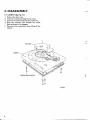
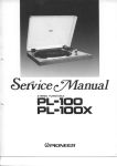
S T E R E OT U R N TABLE
PLIE OOX
(DrrroNeER'
MODELPL-5OOX
COMESIN TWOVERSIONSDISTINGUISHED
AS FOLLOWS:
Type
R€merk3
Voltag€
HET
22OV and 24OV (Switchable)
Europe model (Without cartridge)
HBT
22OV and 24OV (Switchable)
United Kingdom model (Without carrridgo)
CONTENTS
1 . S P E C | F | C A T | .O. N
. .S
.
........
2 . P A N E LF A C I L I T I E S .
3
4
3. DISASSEMBLY
3.1
C a b i n e t ..
6
3.2
Tonearm
7
4. ADJUSTMENTS
4.1
D.D. Motor OperationAdjustment
I
4.2
MechanismAdjustments.
9
5. PACKING
6. EXPLODEDVIEWSANO PARTS LIST
6.1 Cabinet..
0.2 Subpanel
6.3 D.D.Motor...
7 . S C H E M A TDI T
CA G R A M
.......11
.........14
...........16
.........17
8 . P . C .B O A R DC O N N E C T I O N
DIAGRAM
s i s t o fP . C B
8.1 PartL
. oard
A s s e m b l .y. . . . . . 2 1
For description of the D. D. motor, refer to the
PL-630servicemanual(ART-314) and for full auto
mechanism,refer to the PL-3000 servicemanual
(ART-350).
PL-5ClC'x
1. SPECIFICATIONS
Motor and Turntable
Driv€System
.. Direct-drive
M o t o r. . . . . . . . .
. . . . . . . O u a r tP
z L L H a l lm o t o r
TurntablePlatter . . . . . . . . .33ommdism.atuminumalloy die-c6st
lvlomentol lnertie
3ookg{m' {includingplalter matl
S p e e d, .s. . . . . . . .
... 331/3and4srpm
W o wa n d F l u t t e r
.......
L e s st h s n0 . 0 2 5 %( W R M S )
S i g n s l - t o - N oR
i saot i o .
. . . . . M o r er h a n7 5 d B( D l N - B l
(wilh Pioneercartridgemod€l PC-200)
Rotational Characteristica
. . Wirhin 120" rotationar 331/3rpm
Build-upTime
SpoedDeviation..
... Lessthan 0.002%
Speed
v s .L o a dC h a r a c t e r i s t i.c. s. . . . . . . .
Srabtu
e p t o 15 0 g r a m s
drag load
SpeedDrift
. . . . . Lessrhan O.OOOOS%/h
at 33-1/3rpm
Lessthan 0.00o03%/d€gree
temp. ch6ngeat 33-1/3rpm
rA
. . . .. . . . 3
. . . .. . .. 3
. . . .. . . 3
Transistors.
D i o d e s . . . . . . . .
Hall Elements .
Miscellaneous
Power Requirements
Pow€r Consumption
Dimensions
Weight
. 2 2 O | 2 4 O V- ( s w i t c h a b l e ) ,
s0,60H,
......10w
...... 440(W
x ') 1 4 0 { xH3} 8 8 ( D } m r n
1 7 - 1 5 / 1 6 (xWs)- 1 / 2 { Hx) l 5 - 1 / 4 ( D ) i n .
. .9.1ks/201b
Accessories
EP Adapter
Screwdriver
Carlrjdgemounting parts
Carlridgemounting screws.
C a r t r i d g em o u n t r n g n u t s .
C 6 r t r i d g e m o u n t i n g w a s h e r s.
Operating Instructions(French and German furnished on
r n o d e l sf o r H E T )
.1
.1
1
NOTE:
Subfunclions
Specifications and design subiect to po$ibte modification
notice. clue to improvements.
Full auto mechanism, Anti-skating force controf, Stylus pressure
d i r e c t - r e a d o u tc o u n t e r w e i g h t , C u e i n g d e v i c e , S r r o b e l i g h t , F r e e s r o p
hrnges
Semiconductors
lCs
L IN E VO LT A G ES E LE C T ORS WIT C H
).,
v
The line voltageselectorswitch is locatedon the top surface
of the cabinetof this turntable, Before your turntable is
shipped from the factory, the switch is set to the power requirementsof the turntable'sdestination,check that it is
s€t properlybeforepluggingthe power cord into the outlet.
lf the voltageis not properly s€t or if you moveto an area
where the voltage requirements differ. adjust the selector
switchasfollows:
1. Oisconnectthe Dowercord,
2. Provideyourselfwith a medium-sized
screwdriver.
Insert
the tip of the screwdriverinto the grooveof the selector
switch and turn it so that the power voltagemarkingof
your areapoints to the white mark by the arrow on the
label.
Scr€wdriver
without
2. P ANEL FA CI LI T I E S
PL-E'clC'X
O srnnr BUTToN
Whenthis button is depressed,
the power is turned on to
the turntable, the strobe light comeson and the platter
starts to rotate. with the REcoRD slzE SELECToR
set at one of the positions- 30, 25, or I7 - the tonearm
movesautomaticallyto the recorddiscas the platterstarts
rotating, thus starting record play
@ REPEATBUTToN
Pushthis button when you want to listen to the samerecord again.Pressthe button once more to release.
NOTE:
All you have to do fot repeat play is to prcss the REqEAT button.
Therc is no need to push the START and C\JT button again.
@ CUTBUTToN
rE\
lf this button is depressed
whil€ the recordis playing,the
tonearm automaticallyreturns to the arm rest. and the
powerto the turntablewill be cut off.
@ RECORDsIzE SELECToR
This selectorselectsthe sizeof the recordfor automatic
play and alsoselectsmanualplay.
7 " 1 7 . . . . F o r t h e a u t o m a t i cp l a y o f 1 7 c m ( 7 - i n c h )
LP and EP records.
1 0 " 2 5 . . - . F o r t h e a u t o m a t i cp l a yo f 2 5 c m{ 1 o - i n c h )
LP records.
1 2 " 3 0 . . . . F o r t h e a u t o m a t i cp l a yo f 3 0 c m ( j 2 - i n c h )
LP records.
MANUAL.. For the manualplay of records.
NOTE:
The toneam will not be actuated when the RECORD SIZE
SELECTOR is at the MANUAL posiaion fot play, even if the
START button and tha REPEAT button are pushd.
@ ARM-ELEVATIONLEVER
This levercontrolsthe ascentand descentof the tonearm.
U P{ ! ) . . . . .
Thetonearm
rises.
OOWN(l) . . The tonearmdescends
gently.
Set to this position for auto play, auto
repeatand other automaticoperations.
NOTE:
When the ARM ELEVATION
lever is set to the UP position
for automatic play, the toneam will move over as fal as the
lead-in groove on the record but it will not descend and the
rccord will therefore not be played.
KNoB
@ ANTI.SKATE
This knob is usedto cancelout the harmfulskatingforce
which is geneiatedduringrecordplay.
For further details, see "ANTI-SKATING ADJUSTI\4ENT ".
@ nnru REST/CLAMPER
The arm rest supportsthe tonearm when it is not being
used.Set the tonearmon its restwhen it is not playingrecords. Clamp it into position if you don't haveany immediateplansto play records.
PLATTER MAT
O PLATTER/RUBBER
Whenthe tonearmis movedand power is suppliedto the
turntable,the platter will start rotatingat the set rotation
speed.The rubber platter mat stabilizesthe recordsand
alsoabsorbsexternalvibration.
@ DUSTcoVER
Keep this closedunlessoperatingthe controlsor tonearm,
or changingover records.This servesto keep dust from
adheringto the recordsduring record play. When fully
openedand pulled straightup, this dust cover can be removedfrom the cabinet.
@ SPeeoSELECToRBUTToN
45 . . . . . Whenthis button is depressed,
the platterwill
rotate at 45rpm. Depressfor playing 45rpm
records,singlesor EP's.
33 . . , . . When this button is set to the releaseposition,
the platter will rotate at 33-1/3rpm.Release
for playing33-1/3rpmrecordslike Lp,s.
@ STROBELIGHT
This light comeson when the tonearm movesawav from
the arm rest toward the platter. lt irradiatesthe stroboscopearoundthe outsideof the platter.
O TONEARM
This tonearm is designedto apply the correct tracking
force to the cartridgeand to keepthis force at the precjse
levelfor faithful trackingof the recordgrooves.
r
5
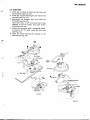
3 . D ISASSE M B LY
3 . 1 C A B I N E T ( S e eF i g . 3 - l l
1. Remove the dust cover.
2. Undo the 4 screws securing the top cover.
3. Undo the 4 screwslocated in the rubber feet.
4. Move the tonearm over towards the center
shaft as shown in the diagram.
5. Disconnect the connectors when lifting off the
cabinet.
Cabinet securingscrews
I I
uu
Fis.3-1
PL-5C'clx
3.2 TONEARM
1. Undo the 4 screws securing the arm base and
the sub-panel (see Fig. 3-2).
2. Undo the 2 screwssecuring the arm base to the
sub-panel(seeFig. 3-2).
3. Disconnect the tonearm lead wires from the
PU board (seeFig. 3-2).
Note that some of the lead wires have been
soldered to the PU board, and must be disconnected with care.
4. Loosen the setscrewswith a hexagonal wrench
to remove the PU plate under the arm base
(seeFig. 3-3).
5. Undo the screw securing the tonearm to the
arm base(see Fig. 3-3)
A
Arm basesecu
f tg. J-z
rrg. J-J
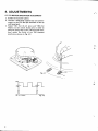
4. AD JU STM E NT S
4 . 1 D . D M O T O R O P E R A T I O NA D J U S T M E N T
l. Rotate the tumtable platter.
2. Connect a dual-imageoscilloscope(or synchroscope) to the TP3 and Q2 terminals of ttre circuit board ass'y.
3. Adjust VR1 (for 33-1/3 rpm) and VR2 (for
45rpm) on the circuit board ass'y in order to
bring the rising edge of the TPb terminal waveform within the width of the TP6 terminal
waveform as shown in Fig. 4-2.
Fiq.4-1
TP3
,
02 (tc=pA2oo4)
a
Fis. 4-2
1
Y
'J
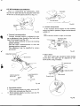
4.2 MECHANISM ADJUSTMENTS
Prior to commencing any adjustments, check
that the PU plate shaft moves along the center axis
of the slot in the sub-panel as shown in Fie. 4-4.
PU platescrew
Fis.4-6
Fis. 44
o Tonearm lowering position
Tonearm lowering position is adjusted by tuming an adjustment screw located in the hole at the
base of the tonearm (see Fig. 4-5).
Tum the screw clockwise to move the lowering
position inwards.
Tum the screw counterclockwise to move the
lowering position outwards.
This adjustment may be simplified by using a
test record .
o Tonearm misoperation
If the tonearm should happen to stop midway
during the lead-in operation, adjust the nut shown
in Fig. 4-7.
This nut should be neither too tight, nor too loo6e.
r
Fis. 4-7
r Short switch
The short switch gap should be 0.5mm during
record play. This gap may be adjusted by the
screw shown in Fig. 4-8 below.
Screwdriver
Adjustingscrew
Loweringposition
too far out
dtIJ
Loweringposition
too tar in
g
Short switch
Rotatorycam
t-
o
i)
Fis.4-5
r Auto-return position
1. If the tonearm retums too earlv. screw the PU
plate screw outwards (see Fig. 4-6).
2. If the tonearm retums too slow. screw the PU
plate screw inwards.
Fig. 4-8
PL-5ClC'X
5. PACK I NG
PartsList
Key No.
1.
2.
3.
4.
5.
6.
7.
8.
9.
10.
11,
12.
't3.
14,
15.
Part No.
PHA-077
H56-603
PBA-079
PRW-O38
PHG-369
Doscription
Caution label
PHC-069
N93.603
KEX,OO2
PRB.135
PRD{46
Cover
45 adaptor
Driver
o p e r a t i n g i n s t r u c t i o n s ( E n g l i s h)
Operating instructions
(French/German)
PEA{32
822426
PXA-720
PXA€76
PXB-125
Rubber mat ass€mbly
H€adshell assembly
Csrtridgemounting screwassembly
6. EXPLODEDVIEWS AND PARTS LIST
6.1 CABINET
#V
56
*#e
fi:,,N.F:
[6?
at'
'/
'o\4P _""-"9:i
84
./A
rar
^&
@
@
g
&
H
tl
d,
1b
,t
PL-5ClC,x
.r
PARTSLISTOF CABINET
K6y No.
NO?ES.
. Parls uithout part number cannol be supplied.
o The I
marh found on some component parts ind.icotes the importance of the
safely loclor ol the part. Therefore, uhen replocing, be sure to use parts of id.entical
desiEnation.
P.rl No.
Doscription
1.
2.
PEA-032
PNR-089
4.
5.
PNX-080
Rubber mal assembly
Turntableplatter
Taprito P screw3x8
Cover
Panel
54.
55.
Pushbutton
PSA3x5
56.
57.
6.
7.
8.
PAC-O24
........
r
16.
17.
r8.
A 20.
f
,
PNW-473
PAG-001
PNW-472
PNX-078
PTr-093
21.
22.
24.
27.
PXB-I03
61.
62.
63.
64.
65.
Holder
Taptite P screw3x10
Neonlamp holder
Taptite P screw3x'l0
Powerlransformer
67.
68.
69.
70,
Taptite P screw4x 10
Spacer
Outputterminal
PSA3x12
EW3
71.
72.
13.
74.
15-
PSA 3x5
Sub panelassembly
76.
11.
78.
79.
80.
31.
It
34.
PAC-O24
A
A
A
)
Angle
TapriteP screw3x10
Speedselectorassembly
Lens
Mirror
30.
/.
{-.
36.
37.
PAG020
PSF-o12
39.
40.
PNV-014
41.
42.
43.
44.
45,
PEC-o5'|
PEC-o51
46.
47.
ra.
49.
50.
Part No.
XWM{33
PDE-044
(HEl
PDG-O21
(HB)
POG_022
Pushbutton unir
Taptite P screw3x l0
Button base
Pushbutton
Start button
PSA3x15
Oustcover
PSF 3x8
Strainrelief
Strainrelief
Angle
Output cord
AC power cord
PNW-475
Selectorlever
PNW-474
P8H-213
Selectorcam
Spring
Description
Steelball 5/32"
Selectorbaseunit
Taptite P scr€w3x10
Circuitbosrd
Taptite P screw3x10
Taptite screw4x8
Hingeassembly
He€dahellassembly
Tonearmassembly
59.
10.
11.
12.
13.
1415.
Key No.
PXA-720
PXB-002
PNW-577
PAC-026
Weightassombly
Arm rest assembly
Elevationsheet
AS knob
Hexagonsocket headlessiel screw4x8
Plasticscrew3x8
PNX-088
PBEOT2
PNW-379
AS springwasher
AS cam
PXT-301
Taptit€ screw3x6
Shatr
EV spring
EW4
EV leverunil
PBK430
EV spring
PNC-O68
PBA-085
PBH-250
AS lever
PLA-396
PBH-201
AS spring
8t.
PNB460
42.
83. PXB-001
83-1.
83,2.
83-3.
83-4.
83-5. PN8-224
83-6. PNB-519
83-7. PXT-l09
83-8. PXT-201
83-9. PBH-045
83,10.
8 3 , 1 1P
. BH-193
Adjust shaft
Spring
Plasticscrew3x l2
Spring
84.
85.
PXBOl0
PSA4x10
D.D. motor
86.
47.
88.
89.
90.
PEB-102
PNW,484
PNW-375
PYY-024
Eiaslever
PU plareassembly
PU plate
Hexagonsocket headlessset screw4x6
EW2 (SUS)
EW3 (SUS)
AS wash€r
Bas€
DampercushionA
Holder
Ring
NO?ES:
o Parts without part number cannot be supplied..
Part No.
Description
91.
92.
93.
94.
95.
PBA-096
PBH-I97
PBH-I96
PBH-198
PBH-198
Screw
Spring
Spring
Spring
Spring
96.
97.
98.
PNW-577
PNT-516
EV sheet
S h e e tc u s h i o n
FW3
Key No,
6.2 SUBPANEL
Key No.
Ptrt No.
99.
100.
PAC-023
101.
102.
103.
104.
105.
x w x - 0 13
PXT-314
PBK-027
PXT-296
PBF-005
Aroo.
s
Dercription
FW3
Knob
Switch assembly
Actuator
Actuator
Actuator
AS knob
PEc-os2
D
B
A
washer
I nsulator
,%
64
61
#
16
17
18
,l
&.'
W,,,
q
&;ss
19
t
{
t
5250
51
o)+.--s8
\\hxr
4t>)==57
34
22
25
44
&
3r,
@=-se
*-.u
4'r
42
-41
#*,
14
FL-5ClC,x
PARTSLISTOF SUBPANEL
Koy No.
1.
2.
3.
4.
Part No.
PXT -297
N5t-786
6.
1.
8.
A 9.
10.
PXT-219
A rr.
A rz.
A rs.
PEc{52
PsF{og
PsF{og
PXM-o8o
14.
PXT-124
16.
11.
18.
19.
20.
PBK-029
Oo3cription
51.
52.
53.
54.
Stopper rubber unit
Polyethylenewasher 4.10x0.25t
Trptit€ screw 3x5
Timing motor
Sub panel unit
56.
57.
58.
59.
60.
lnsulalor
Microswitch
Microswilch
61.
62.
63.
64.
6s.
f
26.
21.
28.
Polyethylenewasher 4.1Oxo.25t
KNA-101
Polyethylenewasher 4.10x0.25t
EW3
P N B - I1 2
Koy No.
EW2
Stopper unit
PM 2.6x6
Stopper
Taptite screw 3x8
,a
21.
22.
23.
24.
25.
NO?'Sr
. Parts without part number cannot be supptied.
66.
67.
68.
69.
70.
Part No.
De.cription
PXT-300
KLA-I59
Start leverunit
Nut
EW2
P X T . 32
r
833-635
PLA-404
PBH-097
PNW-490
PNW-478
PBH-200
PBH-l95
Lock leverspring
PM2.6x8
Collar
Spring
EV cam
EV cam spring
E V l e v e rs p r i n g
EW3
PSA 3x25
Connectorassembly
Lever
EW3
P8H-096
PNW-476
Taptite screw 2x2.6
Cam
30.
f.
rL
31.
32.
33.
34.
35.
36.
KSN-001
PBH,194
PNW{77
38.
39.
40.
PNB-s19
41.
42.
43.
44.
45.
PNB-519
46.
47.
48.
49.
50.
Switch
FW2.6
PM2.6x5
Spring
Selectorplate
EW3
EW3
EW3
EW3
PXT-310
833609
PXT-308
PAKO06
PBF{03
Spring
Rotor unir
Spring
I
15
F
6.3 D.D.MOTOR
,\
Pl!2.6xr0
Pllz.6x
;'
I
7
I
,--@l
a
-
/-{
qr'-
13
g/-
14
A
tit
Y/
I
t'
PSA3XlO
NO?ES:
o Parts without part number cannot be supplied.
PartsList
Fey No.
Part No.
l.
2.
3.
4.
5.
6.
7.
8.
9.
10.
16
PEF-001
PTL-003
PHEO3OFA
Description
Key No.
Rotor assembly
Steel ball
Speed detector assembly
Coreunit
P o s i t i o n a ld e t e c t o r a s s e m b l y
11.
12.
13.
14.
15.
P. CB
Base
Hall element
Cord fixer
Angle
16.
Part No.
MNT-001
MNW-001
PDE-O38
Description
Base
Ring
Plate
Cover
Connector assembly
Taptite screw 3x8
7 . S C H E M A T I CD I A G R A M
CONTROL
arJytrzzl xwtra-O33
10n6
+
QI
PD1003
Q2
PA2004
to
()
v,
a
x- +Rl
rau Ha.7
l't
c2
56p
f,
(r
cI1 0.47/35
.t!
oo
u>
uo
c12 0.t8
I
x
-_vvl
R2
1k
U-
. Ld<>
!
Hfid
OI
X-TAL
PSS-OO3
G
dH
p>
l ! O
t
SE
uJ|r)
zu,
lrJ (9
G <
lrj F
lR3
Lloo
))
\ I
dP
|!J
lrJ O
G >
i;
E,
lr,
F
E
<9
I L Z
o
(J
Er
E O
I(9
3E
c9
o.o4
N
e
|!
rf
t|
|l
c8
100
/6.3
(NP)
R02
AC POWER CORD
l--
l s 5
I
SPEED
I
s5
swtTcHAss'y XWX-013
A
D 1 S IR B A l O ( P c x - o r o )
r----
----t
Q4
2SC945-P
I
PSG-Or5
AC POWER
CORD
TP3 TP2
TPl
-J
o5
2sD234
+
t
c23
100
/35
LINE VOLTAGE
ECTOR
p66'l-oztrxo
DZ YtZ-Z$r
sra
START
/ REPEAT
PSF-ol2
R14
820
Q6
52A
CUT(STOP)
PSF-Or2
15 18 8 8 o r l N 4 O O 5
BRN\
r-- --
l o *
s4
^ s 4 M t c R (os r o P )
PsF-ooe
A
i
i
Q6
Rt13 4
2SC
FL-5OCIX
l-I
R11
680
(1w)
Q3
+c20.
xlo
/35
P A2 0 0 5
R102.2U/2W)
(r
lr.l
E
o
=zo
lrl
-
\
trj
E5
Otr
la
3& -1::l
z
O J
<
't -r 2
8
e
cu)
I
<&
(lo
E
( ) ( rt
l!
9 t c
i3E
TE
lrJ
F
E
> t^l
\ >
ILZ
o
o
O F J
>an
(L
o
F
@
I
Y
g
(9
z
()=
z
z 9
F
rff
:o
N
HE
TL
lfoot
a
e:2
( l F u r
IO
u
< >
> F t r l
L'
G
P
trtC)G
( r G O .
H3 Tooo'
I
o
z
H'lrr
fl3
PHE - 3O3FA
VR1
VRz
SPEED ADJ (33Tl3)
SPEEO ADJ (45)
PCP-OI2
PCP - O3I
,BLK
/WHT
i / l
MoroR ass'y
PxB- olo
I
I
Q4
zSC945-Por Q
Q5
250234
02 wz-280
1. R E SI S T OR S :
f ndicated in Q , t/oW,t5% tolerance unless otherwise noted k : kCl,
M : M a , ( F ) : ! 1 o / o (, G ) : t 2 o / o (, K ) : t 1 0 % t o l e r a n c e
2. CAPACITORS:
Indicated i n c apac i ty ( !F ) /v ol tage ( V) unl es sother w i s e noted p : pF
Indicatio n w i thout v ol tage i s 50V ex c ept el ec tr ol y ti c c apac i tor .
3 . V O L T A G E , C U RR E N T :
: D C v ol tage ( V) at no i nput s i gnal
U
mA: D C c ur r ent at no i nput s i gnal
fr
o6
Rr6
8 . 2k
(2w)
Q6
R13 4.7k
2SC1279-S
4 . O T H ER S :
@ : Adj us ti ng poi nt.
The
m ar k found on s om e c om ponent pafts i ndi c ates the i m A
portance of the safety factor of the part. Therefore, when replacing,
be sure to us e par ts of i denti c al des i gnati on.
NE-
W HT
A
NEON
PEL-O39
S W I T C HE S :
SI : ST AR T / R EPEAT
ON - OF F
32 : C U T ( ST OP)
ON - OFF
53 : MICRCXSTART/REPEAT)
ON - OFF
54: MICRO(STOP)
ON - OFF
55 : SPEEDSELECTOR 331/3rp
45rpm
58 : LINE VOLTAGE
551E9198'UG.24OV
The underlinedindicates
the switcfrpositi6nThis is the basicschematic
diagram,but the actualcircuit may vary
dueto improvements
in design.
1E|
8. P.C. BOARD CONNECTION
DIAGRAM
CUT(ST
MOTORAss'yPXB{10
SUBPANELAss'yPXB-I03
I-
-
ruorbn-l
CONTROLAss'YXWM€33
S'IIVITCH
Ass'yXWX-013
START REPEAT
lss'yPXB-I03
[-or.onl
I
lvI
l
-
t - - - - - l
0L As'y XWM{33
trL-5ClC'x
8.1 PARTSLISTOF P,C.BOARD ASSEMBLY
NO?ES:
. When ordering resistors, first conuert reaiatonce ualues into code form as shobn in
the following exomples.
Ex. 1 When there ore 2 effectiue digits (onf digit aport from 0), such as 560 ohm
and 47h ohm (tolerance is shown by J = Sy", and K = I0T").
560'l4 7h e
0.5r)
.lo
5 6 xt O '
4 7 xI O l
o R '. . . .
0 1 0. . . .
56L........
173.........
E D I . PESO [ ! J
R D q . P@SA A J
. . . . . . R N 2O
r i E t sK
. . . . . . R S /oPl n oK
Etc. 2 When there orc 3 effectiue d.igits (such as in high precision metal film resis.
c
a
5.62hf,
562 x 10'
5 6 2 1 . .... . . . . R N ' z sER6 E n .
The A marh found on some component ports indicates the importance of the
safety factor of the part. Therefore, uhen replacing, be surc to use parts of
id en t ical d esig na t io n.
CONTROLASSEMBLY(XWM-033}
CAPACITORS
SEMICONDUCTORS
PsrtNo.
-
Symbol & D.sciaption
ccDcH 330J50
ccDcH s60.J50
CKDYF103250
cKDYF4032s0
CKDYA68'tK 50
cl
cszA R47K35
coMA 184J50
coMA 104K50
coMA t 04J50
cEA 010Ps0
cl 'l
c12
c13
c14
c16
cszA 100K16
cEA 1ooP35
CEA471M50L
c E A 1 0 1 P3 5
cEA 100M250L
cl7
cl8, C20
c2l
c22, C23
c25
c3, c5-c7, cr5. c24
c10
, t
cEA 100Pt6
C E A1 0 1 M6 . 3 N P
A pcl.ogn
c8
Note: When orde ng resistors, conuert the
RESISTORS
resistance ualue into code form, ond
then rewrite the part no. os before.
P.n No,
Symbol & Ocacription
RD/.PSNtrO J
RD%PS2R2J
R S l P6 8 1 J
RS2P1O2J
RS2P822J
R 1 - R 9 ,R 1 5
R10
R11
R12
R16
PCP{12
PCP-031
VR2
P.rt No.
POr 003
PA2004
PA2005
2SC945-P
{2SC945-O)
2SO234
2SC12795
SIRBA,IO
wz2ao
Symbol & Derc.aption
o1
o4
o5
D1
1Sr888 (1N4005)
OTHERS
Part No.
Symbol & D€scliption
PSS{O3
A pELosg
PNW482
Crystal
Neon lamp
Neon lamp base
PM3x5
PSA3x8
A KKR-ool
l\ PEK{23
A PEKo33
Fuse holder
(XWX-013)
s1'vtTcH
ASSEMBLY
Part No.
PSG€15
Symbol & D.sc.iption
Pushswitch
PSA3x5
POSITIONAL
DETECTORASSEMBLY
Symbol & Oescription
PHE.3O3FA
RO%PS241J
H a l l e l e m e n l ( H ' 1 ,H 2 , H 3 )
R 101-R I 03
21
a-1. M.eurc 1-chom6. M€su.o-ku. rokyo 1s3, J6psn
FlCtNIltl
ELECTFICINIC
CCIFIFCIFIATICIN
tt a. tEi|lll
]..GltaoialCa
CC'IFCnAIEIN
E'5 Oxro.d O.ivo, Moon.chr.,
N.w Jo€€v o7o74. rr.s.A.
t6[l
Eaqllorcl
C|JIO?D
N.v. Luith.9.n-H.v6n
9, eo3o anrw6rp, Et.rg'um
tri[a
lllcrltEnlca
ALraYFAlr^
1 78- 1 s4 Bound6Fv to€d, 8..;6'd6,
FrY. !fu.
v€so.,E 3 I 95. ausr.6ha