1
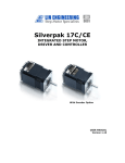
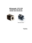
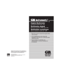
66430
Digital Multimeter
Owners Manual Model 66430
Multímetro digital
Manual del propietario modelo 66430
• Read this owners manual thoroughly before
use and save for future reference.
• Lea completamente este manual del
propietario antes del uso y consérvelo para
referencia futura.
Designed and manufactured to the specifications of
Diseñado y fabricado según las especificaciones de
P.O. Box 3241
Milwaukee, WI 53201-3241
414-352-4160 • 1-800-228-5123
Rev. E
Contents
1. Meter Functions
Figure 1
1. Meter Functions
2. Specifications
2.1
For Your Safety
3. Operating Suggestions
31 ⁄ 2 Digit LCD Display
4. Common DC Voltage Measurements
4.1
4.2
4.3
Automotive Voltage Tests
Alternators and Generators
Household Batteries
5. DC 10 Amp Measurement
5.1
AC Volts
DC Volts
500
500
Common DC Amperage Measurements
˜
DC Amps
6. AC Voltage Measurement
6.1
6.2
6.3
Wall Receptacles
Appliance Receptacles
Circuit Breaker Panels
10 Amps DC
7. Resistance/Continuity Measurement
10A MAX
7.1
7.2
7.3
7.4
7.5
7.6
7.7
Spark Plug Wires
Extension Cords
Appliance Cords
Fuses
Switches
Heating Elements
Thermostats
750V AC
1000V DC
200mA MAX
Resistance
66430
500V MAX
Input Jacks
8. Diode Check
9. Battery Replacement
1
Diode Test
Function
2
2. Specifications
Ranges:
DC Voltage:
AC Voltage:
DC Current:
Resistance (ohms):
Diode Check:
Accuracy:
Function/Range switch:
Display:
Polarity Indication:
Weak Battery Indicator:
Battery Life:
Battery Type:
Overrange Indication:
! WARNING Replace worn test leads. Do not use test leads
with broken or tattered insulation.
6) ! WARNING Discharge a capacitor before measuring it.
7) Remove the test leads from the circuit being measured
as soon as the test is completed. Never reset the
function/range switch to another range while the leads
are still in contact with a circuit.
8) Do not measure voltage when the function/range switch
is set on the resistance (ohms) or the current (10 Amp)
settings. Do not measure current when the meter is set
on the resistance range. Never measure AC voltage
when the meter is set on DC voltage or the 10 Amp range.
Setting the meter on the incorrect function may burn out
some of the internal circuitry and may pose a safety hazard.
5)
18 measuring ranges
200 mV-2000 mV-20-200-600 Volts
200-500 Volts
200µA-2000µA-20mA-200mA
0-10 Amps on a separate jack (unfused)
200-2000-20K-200K-2 Megohms
Used for checking condition of diodes
DC voltage +/- (.7% + 2 digit)
AC voltage +/- (1.2% RDG + 5 digit)
DC current +/- 1.5%
Resistance +/- (0.8% RDG + 2 digit)
5 functions
20 positions
18 measuring ranges
3.5 digit LCD readout
“(-)” is displayed for negative polarity
“BT” is displayed when insufficient
battery life remains
100 hours with carbon-zinc cells, 200 hours with
alkaline cells under normal conditions.
Uses one 9 volt carbon-zinc or alkaline battery
The three least significant digits are blank and
the number “1” is displayed at the left when the
range capacity is exceeded by the input.
GMA-250 mA
3. Operating Suggestions
1) Use extreme caution when checking electrical circuits.
2) ! WARNING Do not stand in wet or damp work areas when
working with electricity. Wear rubber soled boots or shoes.
3) ! WARNING Do not apply more voltage or current than the
set range of the multimeter will allow.
4) ! WARNING Do not touch the metal probes of the test leads
when making a measurement.
1) Set the function/range switch to the proper position before
making a measurement. When the voltage or current is not
known, it MUST be determined that the capacity of the
selected range will handle the amount of voltage or current
in the circuit (see #3 under “For Your Safety”).
2) Avoid placing the meter in areas where vibration, dust
or dirt are present. Do not store the meter in excessively
hot, humid or damp places. This meter is a sensitive
measuring device and should be treated with the same
regard as other electrical and electronic devices.
3) When the meter is not in use, keep the function/range
switch in the OFF position to keep the batteries
from discharging.
4) When disconnecting the test leads from the unit, always
grasp the leads where the input jacks meet the tester
housing. Do not pull the leads out of the jacks by the
insulated wire or transport the tester using the test leads as
a carrying strap.
5) ! WARNING Do not immerse the meter in water or solvents.
To clean the housing use a damp cloth with a minimal
amount of mild soap.
NOTE: With any measurement made by this meter, there will
be some fluctuation of the digital display. This is due to the
meter’s sampling method. This unit samples at a rate of 2
times per second, thus the fluctuation of the readout.
3
4
Replacement Rating:
Important:
Read this operators manual thoroughly before using this multimeter. This
manual is intended to provide basic information regarding this multimeter and
to describe common test procedures which can be made with this unit. Many
types of appliance, machinery and other electrical circuit measurements are
not addressed in this manual and should be handled by experienced
service technicians.
! WARNING USE EXTREME CAUTION WHEN USING THIS MULTIMETER.
IMPROPER USE OF THIS METER CAN RESULT IN SEVERE DAMAGE TO
PROPERTY, SEVERE PERSONAL INJURY OR DEATH. FOLLOW ALL
INSTRUCTIONS AND SUGGESTIONS IN THIS OPERATORS MANUAL AS
WELL AS OBSERVING NORMAL ELECTRICAL SAFETY PRECAUTIONS. DO
NOT USE THIS MULTIMETER IF YOU ARE UNFAMILIAR WITH ELECTRICAL
CIRCUITS AND PROPER TEST PROCEDURES.
2.1 For Your Safety
4. Common DC Voltage Measurements
1) Set the function/range switch to the DC voltage range.
2) If the polarity of the circuit to be tested is known, touch
the black test lead to the neutral side. If the polarity is
unknown, touch the test leads to opposite sides of the
circuit. If the test leads are reversed, the “(-)” indicator will
appear on the display. Reverse the test leads for proper
polarity and read the value indicated on the display.
4.1 Automotive Batteries
! WARNING Always wear safety goggles and gloves when
working near batteries.
! WARNING Batteries contain sulfuric acid. Avoid contact with
clothing, skin, and eyes. If electrolyte comes in contact with
eyes, flush with water for at least 15 minutes and seek
immediate medical attention. If electrolyte comes in contact
with skin rinse it off immediately with water.
! WARNING Batteries release hydrogen gas that is very
explosive. Keep sparks and flames away from battery and
never smoke while working with or near a battery.
! WARNING Always disconnect the negative battery terminal
first and reattach it last to prevent sparks.
! WARNING Running an engine produces carbon
monoxide which can cause serious injury or death. Keep
the service area well ventilated or attach an exhaust gas
extraction system.
4.1a Battery Voltage Test
To remove the battery’s surface charge and ensure an
accurate reading, turn the headlights on high for 15 seconds,
turn them off, then let the vehicle sit for a few minutes before
making the measurement. With the engine and all
accessories turned off, disconnect the battery’s black (-)
negative cable. Next remove the red (+) positive battery
cable. For stubborn top post terminals use terminal puller
Calterm #30015 (available in your local auto parts store) to
remove terminals without damaging the posts. Use a terminal
and post cleaner such as Calterm #30009, 10, 11, or 12 to
remove oxidation and corrosion from the terminals and battery
posts or mounting surface. Battery anti-corrosion cleaner
5
Calterm #30115 can be used to ensure a clean connection.
Set the function dial on the meter to the 20 volt DC setting.
Touch the negative (-) probe of the meter to the (-) negative
battery terminal and the (+) positive probe of the meter to the
(+) positive battery terminal. The display should read at least
12.4 volts on a 12 volt DC battery. If it reads less than 12.4
volts the battery should be charged before proceeding with
any other tests.
Slip chemically treated anti-corrosion washers Calterm #30098
between the battery and the battery cable terminals prior to
reinstalling the cables to prevent future corrosion. Reinstall
and tighten the positive (+) cable first. Next reinstall and
tighten the negative (-) battery cable.
4.1b Running Voltage Test
This test provides a quick indication of whether the charging
system is functioning properly.
! WARNING
Use caution not to contact cooling fan or belts as
serious personal injury may result. Always fully engage the
parking brake and place the automatic transaxle in P (Park) or
manual transaxle in N (Neutral) before performing tests with
the engine running.
Start the engine, and increase the RPM to approximately
2000. Set the function dial on the meter to 20V DC. Check
the battery voltage by touching the negative (-) probe of the
meter to the negative (-) battery terminal and the positive (+)
probe of the meter to the positive (+) battery terminal. With
the engine running the battery voltage should be between
14-15 volts. If the voltage is over 15 volts there may be a
problem with the voltage regulator. See a troubleshooting
manual specific to your vehicle for additional information.
4.1c Cranking Voltage Test
This test provides a fast overall check of the starting system.
! WARNING Use caution not to contact cooling fan or belts as
serious personal injury may result. Always fully engage the
parking brake and place the automatic transaxle in P (Park) or
manual transaxle in N (Neutral) before performing tests with
the engine running.
6
Touch the negative (-) probe of the multimeter to the (-)
negative battery terminal and the positive (+) probe of the
multimeter to the positive (+) terminal of the battery. To
prevent the engine from starting, disconnect the coil
secondary wire from the center of the distributor cap and place
it against the engine block. On HEI distributors, remove the
connector from the terminal marked "BAT" to keep the engine
from starting. On DIS or electronic ignition systems remove
the connector going into the ignition module or modules. With
the ignition disabled, parking brake fully engaged, and manual
transmission in N (neutral) or automatic transmission in P
(Park), have an assistant crank the engine while you read the
meter. Only crank the engine long enough to obtain a fairly
steady reading on the multimeter. On a warm engine the
cranking voltage should be above 9.6 volts when the engine is
cranking at normal speed. If the voltage drops below 9.6 volts
while cranking the engine the battery needs to be charged. If
the battery is fully charged and still dropped below 9.6 volts
the battery should be load tested with a load tester and will
likely need replacement. Reattach wire to distributor or
ignition module after completing this test.
4.1d Battery Drain Test (DC Amps)
This test determines if an excessive constant drain on the
battery is present. Remove the negative terminal from the
battery. Turn off all accessories in the vehicle, REMOVE THE
IGNITION KEY FROM THE IGNITION, and remove the
underhood lamp. Disconnect the black (-) negative cable from
the battery. Set the function selection dial on the multimeter to
the 2000m setting for DC A. Touch one lead to the negative
battery cable end and one lead to the negative battery
terminal. After confirming that the reading is less than 200mA
the selection dial may be changed to the 200m setting for DC
Amps. If the reading is less than 20mAmps set the function
dial to the 20m DC A setting. Normal parasitic load exists
from accessory circuits including: ABS, remote keyless entry,
anti-theft systems, radio, CD changer, fog lamps, and the
powertrain control module. Compare the reading on the meter
to the specifications provided by the vehicle’s manufacturer.
As a general rule the normal parasitic load on most vehicles
with all accessories off and the key removed from the ignition
7
should not exceed 15 milliamps. Check your vehicle's
specifications to determine acceptable parasitic load. If the
reading is beyond the specified limit, begin removing fuses in
a systematic way while watching the reading on the
multimeter. When the removal of a fuse causes the reading to
drop, you have identified that one or more of the circuits
protected by the fuse is a source of the drain on the battery.
4.2 Alternators and Generators
Set the function/range switch to the 20 volt DC range. While
the engine is idling at normal operating speed, touch the black
(-) test lead to the metal framework of the vehicle, then touch
the red (+) test lead to the output terminal connector. The
alternator output cable is always the heaviest gauge cable
attached to the alternator (see fig. 2). The display should read
12 volts or more. If the display fluctuates rapidly, the cable
may need to be tightened. If the engine is idling lower than is
specified in the vehicle owners manual, the voltage reading
will be lower. If the output voltage is significantly low, the
alternator may require service or replacement.
! WARNING When making automotive measurements,
observe safety precautions. Stay away from the fan blades,
belts and other moving parts of the engine. Keep the
multitester and its leads away from moving parts. Always fully
engage the parking brake and place the automatic transaxle in
P (Park) or manual transaxle in N (Neutral) before performing
tests with the engine running.
Figure 2
4.3 Household Batteries
Set the function/range switch to the 20 volt DC setting. Touch
the red (+) lead to the (+) terminal of the battery and the black
(-) lead to the (-) terminal of the battery. Read the voltage level
of the battery on the display. Generally speaking, if a battery’s
output voltage falls below 60% - 70% of its original rating, it
should be replaced.
8
5. DC 10 Amp Measurement
A separate input jack is provided for measurement of DC
current up to 10 Amps. This range is not fused so it is
imperative that the circuit under test does not exceed 10
Amps. Additionally, this function is designed for intermittent
use only. Maximum contact time of the test leads with the
circuit is 15 seconds, with a minimum intermission time of
30 seconds between tests.
1) Set the function/range switch to the 10 Amp range with
the leads in their proper jacks.
2) Touch the test leads to the circuit in series (in line with
the circuit) so that the circuit current passes through the
multitester. That means the test leads and the meter are
a “conductor” in the circuit. Read the amperage value
on the display.
test for proper grounding of the receptacle, touch one test lead
to the “hot” (narrow) side of the receptacle, and the other test
lead to the ground slot (fig. 3B). The tester should read 120 V
AC as before. To test for proper grounding of non-polarized
receptacles (fig. 4), alternately touch the test leads between
the receptacle slots and the wall plate screw. The tester should
indicate 120 V AC when one test lead contacts the “hot” side of
the receptacle. If ground contact cannot be made on the wall
plate screw, remove the wall plate and touch the electrical box
with the test lead in the same manner as before. The tester
should read 120 V AC with one test lead touching the electrical
box and the other touching the live side of the receptacle. If
not, the receptacle is not properly grounded.
Figure 3
5.1 Common DC Amperage Measurements
The DC 10 Amp range of this tester is primarily used in
automotive circuit measurements which use battery power.
Frequent applications encountered with the 10 Amp feature
include troubleshooting headlight wiring, trailer wiring, auto
stereo and speaker systems, RV appliance wiring and other
automotive accessories that draw current from 1 to 10 Amps.
Any circuit powered by batteries or DC generators which
generate 1 to 10 Amps can be measured with this unit.
! WARNING
DO NOT APPLY VOLTAGE TO THE TEST LEADS
WHILE THE TESTER IS SET IN THE 10 AMP RANGE. See #8
“For Your Safety”
6. AC Voltage Measurement
1) Set the function/range switch to the appropriate
AC V range.
2) Touch the test leads to the circuit under test. With AC
voltage, the polarity of the test leads is not a factor.
Read the voltage level of the circuit on the display.
3B.
3A.
Figure 4
6.2 Appliance Receptacles
Set the function/range switch to the 750 V AC setting. Touch
the test leads to the receptacle slots. The tester should read
240 V AC between the two “hot” sides of the receptacle, and
120 V AC between the neutral slot and either of the two “hot”
sides (fig. 5).
Figure 5
6.1 Common AC Voltage Measurements
Wall Receptacles
If the receptacle is controlled by a switch, make sure the switch
is ON. Set the function/range switch to the 200 AC V setting.
Touch the test leads to the “hot” and “neutral” slots of the
receptacle (see fig. 3A). The display should read 120 V AC. To
9
neutral
6.3 Circuit Breaker Panels
To test for defective circuit breakers, set the function/range
switch to the appropriate AC V setting. Touch one test lead to
the neutral (buss) terminal strip of the breaker panel and the
10
other test lead to the terminal on the circuit breaker
(see fig. 6). The tester should read 120 V AC.
Figure 6
7. Resistance/Continuity Measurement
leads) does not matter when checking continuity or measuring
resistance. Compare the reading to specifications in a service
manual for your vehicle. Good spark plug wires typically have
~ 3K ohms per foot, which may vary based on
a resistance of =
the style of the plug wire. If the wire has an open (break in the
conductor) the meter will indicate a “1” on the left side of the
display. Make sure that you are contacting both terminals with
the tester probes before making your diagnosis. If the
resistance is beyond the specification in your service manual
the plug wire will need replacement. Check and replace each
plug wire one at a time to avoid mixing up the wires.
For resistance and circuit continuity testing with power OFF:
1) Set the function/range switch to the appropriate ohms
setting. If basic circuit continuity tests are being made,
any of the ohms settings will do.
2) Touch the test leads to the resistor or non-energized
component to be measured. Use the 2000K range when
testing for resistance values in electronic components
such as resistors and potentiometers. If the value of
the component falls within the range of another setting,
reset the function/range switch to that setting for a more
accurate reading.
Common resistance and continuity measurements
Continuity tests are probably the most frequently performed
electrical troubleshooting procedures around the home.
Always remember that continuity checks are to be made with
the power to the circuit turned OFF. Polarity of the test leads is
not a factor in making continuity checks.
7.1 Spark Plug Wires
! WARNING Always remove power to the circuit before using
the multimeter in the ohms position to measure resistance or
check for continuity.
With the engine and ignition turned off, remove one spark plug
wire and visually inspect both terminal ends for corrosion;
inspect the wire’s insulation for damage. Replace the spark
plug wire if corrosion or wear is visible. Set the function dial
on the meter to the 20K ohm setting. Contact one terminal
end with one tester probe and the other terminal end with the
other tester probe (see fig. 7). The polarity (direction of the
11
Figure 7
Figure 8
7.2 Extension Cords
Unplug the cord. Set the function/range switch to any of the
ohms settings. Touch one of the test leads to one of the metal
prong ends of the cord and insert the other lead in either one
of the receptacle slots on the other end of the cord, making
sure both leads are making good contact (see fig. 8). If the
display does not change, switch one of the test leads to the
opposite receptacle or prong, making sure of good contact.
If the display still does not change, the cord may need to
be replaced.
7.3 Appliance Cords
Unplug the appliance from its power source. Turn its power
switch to the ON position. Touch the test leads to the metal
prong ends of the cord. The tester should indicate a low
resistance value. If not, flex the cord while the leads are still in
contact with the metal prongs. If the display changes
erratically while the cord flexes, there may be a broken
conductor in the cord. If the display does not change at all
there may be an open circuit in the appliance. Should it be
determined that the cord is not the source of the problem, the
appliance may need to be disassembled in order to pinpoint
the problem. Refer to the owners manual of the appliance.
The manufacturer of the appliance may require that the
appliance be serviced only by a qualified repair technician.
12
7.4 Fuses
Note: With the power OFF, always remove a fuse from its
socket before testing it. With mini, maxi, or cartridge fuses,
touch the test leads to each end of the fuse (see fig. 9 & 10).
If the fuse is good, the display should read -0- ohms. If the
display doesn’t change at all, replace the fuse. On plug-type
fuses, touch the test lead on the bottom contact and the other
on the threaded metal contact (see fig. 11). On time-delay/
tamper-proof fuses, the other metal contact is at the top of the
ceramic threads.
element and observe the display. The reading should indicate
low ohms. If the display doesn’t change, the heating element
may be broken. If the element(s) show that continuity exists,
test for continuity of the circuit(s) that feed the element(s).
7.7 Thermostats
Make sure the thermostat control is in the OFF position.
Remove the thermostat cover. Touch the test leads to the
contact points on the thermostat. The display should read -0ohms. If not, either one of the contacts may be loose or broken.
8. Diode Check
Figure 10
Figure 9
Figure 11
7.5 Switches
Cut off the power source to the switch. If necessary,
remove the switch. Turn the switch to the ON position and
touch the test leads to the switches terminals (see fig. 12). If
the switch is good, the display should read -0- ohms. If the
display doesn’t change at all, replace the switch. On other
than two-way SPST (single pole, single throw) switches such
as three-way light switches or double pole double throw
(ON-OFF-ON) switches, in each ON position you will need to
alternate the test leads between the switches terminals to
determine which two terminals control that ON position.
Diodes should be tested with both forward and reverse
voltages applied:
1) Plug the red (+) test lead into the (+) input jack, and the
black (-) test lead into the COM input jack. Set the
function/range switch to the diode test setting ( ).
2) Touch the test leads to the diode, one lead on the anode
and the other on the cathode. The indication of a diode in
good condition is a low resistance reading when the red
lead (+) is on the anode and the black (-) lead is on the
cathode. When the test leads are reversed (reverse voltage
is being applied), the meter should display a
"1" on the left side of the display if the diode is good.
NOTE: A low resistance in both directions indicates a
shorted diode; a high resistance in both directions indicates
an open diode. In either case the diode is defective and
should be replaced.
9. Battery Replacement
Figure 12
1) Remove the screws in the back cover of the tester and
carefully separate the back cover from the front.
2) Note the polarity of the battery terminals when removing it
from its connector and replace.
7.6 Heating Elements
Household appliances such as coffee makers and water
heaters contain heating elements which may require
troubleshooting. When making continuity checks on heating
elements, disconnect the element(s) from the circuit(s) that
supply it/them. Touch the test leads, one on each end of the
13
3) Carefully replace the back cover and tighten the screws.
Do not overtighten the screws as this may strip the threads
in the tester housing.
14
ORDER FORM
Learn more about using multitesters with “How To Use Your
Multitester For Electrical Testing and Troubleshooting”. A
160 page guide to using analog and digital multitesters.
Contains nine chapters of easy to understand instructions
on basic household, automotive electrical and electronic
circuit testing. Packed with illustrations. Paperback bound.
Available wherever multitesters are sold or:
Send check or money order for $15.23 per copy ($13.23
plus $2.00 per copy shipping and handling) to:
Gardner Bender
6101 N. Baker Rd.
Milwaukee, WI 53209
PLEASE PRINT CLEARLY
Name__________________________________________________
Address________________________________________________
City______________________State__________Zip_____________
Qty. Ordered________________________
15
16
Contenido
1. Funciones del probador
Figura 1
1. Funciones del probador
2. Especificaciones
2.1 Para su seguridad
3. Sugerencias de operación
Pantalla LCD de 31⁄ 2 dígitos
4. Medidas comunes de tensión continua
4.1 Baterías automotrices
4.2 Alternadores y generadores
4.3 Baterías (pilas) domésticas
5. Medición de 10 amperios DC
Voltaje AC
Voltaje DC
500
500
5.1 Mediciones comunes de amperaje DC
˜
Amperaje DC
6. Medición de voltaje AC
6.1 Receptáculos de pared
6.2 Receptáculos de aparatos
electrodomésticos
6.3 Tablero de cortacircuitos (disyuntores)
7. Medición de resistencia/continuidad
7.1
7.2
7.3
7.4
7.5
7.6
7.7
Cables de la bujía
Cables de extensión
Cables de aparatos electrodomésticos
Fusibles
Interruptores
Elementos calefactores
Termostatos
10 amperios DC
10A MAX
750V AC
1000V DC
200mA MAX
Resistencia
66430
500V MAX
Enchufes
8. Revisión de diodos
9. Reemplazo de la batería
17
Prueba de
diodos
18
2. Especificaciones
3)
Escalas:
Voltaje AC:
Corriente DC:
4)
18 escalas de medición
200-500 voltios
200µA-2000µA-20mA-200mA
0-10 amperios en un enchufe
separado (sin fusible)
Resistencia (ohmios):
200-2000-20K-200K-2 Megaohmios
Prueba de diodo:
Utilizada para revisar el estado de diodos
Precisión:
Voltaje DC +/- (0,7% + 2 dígitos)
Voltaje AC +/- (1,2% RDG + 5 dígitos)
Corriente DC +/- 1,5%
Resistencia +/- (0,8% RDG + 2 dígitos)
Selector de función/escala:
5 funciones
20 posiciones
18 escalas de medición
Pantalla:
De cristal líquido (LCD) de 3-1/2 dígitos
Indicación de polaridad:
Se presenta "(-)" para la polaridad negativa
Indicador de batería agotada: Se presenta "BT" cuando se ha agotado
la batería
Duración de la batería:
100 horas con pilas de carbono-zinc o 200 horas
con baterías alcalinas bajo condiciones normales
Tipo de batería:
Utiliza una batería de carbono-zinc o alcalina
de 9 voltios
Indicación de escala excedida: Los tres dígitos menos significativos quedan
en blanco y el número "1" aparece a la izquierda
cuando la entrada supera la capacidad de
la escala
Fusible de Reemplazo:
GMA-250 mA
5)
6)
7)
8)
! PRECAUCION No aplique más voltaje o corriente de lo
permitido por la escala seleccionada en el multímetro.
! PRECAUCION No toque las puntas metálicas de los
conductores de prueba cuando realice mediciones.
! PRECAUCION Reemplace los conductores de prueba
desgastados. No use conductores de prueba con
aislamiento roto o agrietado.
! PRECAUCION Descargue un condensador antes de medirlo.
Retire los conductores de prueba del circuito bajo prueba
tan pronto concluya la prueba. Nunca cambie de una
escala a otra por medio del selector de función/escala
mientras los conductores estén todavía en contacto con
un circuito.
No mida el voltaje cuando el selector de función/escala
esté colocado en la posición de resistencia (ohmios) o de
corriente (10 amperios). Nunca mida la corriente cuando el
selector esté colocado en la escala de resistencia. Nunca
mida el voltaje de corriente alterna (AC) cuando el selector
esté colocado en la escala de voltaje de corriente continua
(DC) o de 10 amperios DC. Si el probador se usa en la
función incorrecta, se pueden fundir algunos de los
circuitos internos, resultando en un riesgo de seguridad.
Importante:
3. Sugerencias de operación
Lea este manual del operador completamente antes de utilizar este multímetro. El
fin de este manual es proporcionar información básica relacionada con este
multímetro y describir procedimientos básicos de prueba que pueden realizarse
con este probador. La medición de muchos tipos de aparatos, maquinaria y otros
circuitos eléctricos no se menciona en este manual y debe solicitarse la asesoría
de técnicos de servicio experimentados.
1) Coloque el selector de función/escala en la posición
correcta antes de efectuar una medición. Cuando se
desconozca el voltaje o la corriente, DEBE determinarse
que la capacidad de la escala seleccionada acepte la
cantidad de voltaje o corriente del circuito (vea el No. 3
bajo la sección "Para su seguridad").
2) Evite colocar el probador en áreas donde exista vibración,
polvo o suciedad. No almacene el probador en lugares
excesivamente calientes, mojados o húmedos. Este
probador es un dispositivo de medición sensible y debe ser
tratado con el mismo cuidado que otros dispositivos
eléctricos y electrónicos.
3) Cuando no esté en uso el probador, mantenga el selector
de función/escala en la posición apagada (OFF) para
conservar la batería.
4) Cuando desconecte los conductores de prueba del
probador, siempre tómelos desde donde los enchufes se
encuentran con la caja del probador. No tire de los
! PRECAUCION PRECAUCION SEA SUMAMENTE PRECAVIDO
CUANDO USE ESTE MULTÍMETRO. EL USO INDEBIDO DE ESTE PROBADOR
PUEDE PROVOCAR GRAVES DAÑOS MATERIALES Y LESIONES
PERSONALES GRAVES O FATALES. SIGA TODAS LAS INSTRUCCIONES Y
SUGERENCIAS DE ESTE MANUAL DEL OPERADOR Y OBSERVE ADEMAS
LAS PRECAUCIONES NORMALES DE SEGURIDAD ELECTRICA. NO UTILICE
ESTE MULTIMETRO SI NO TIENE EXPERIENCIA EN CIRCUITOS ELECTRICOS
Y DESCONOCE LOS PROCEDIMIENTOS CORRECTOS DE PRUEBA.
2.1 Para su seguridad
1) Sea sumamente precavido cuando revise circuitos eléctricos.
2) ! PRECAUCION Aléjese de las áreas mojadas o húmedas
cuando trabaje con electricidad. Use botas o zapatos con
suelas de goma.
19
20
conductores por el cable aislado para sacarlos de los
enchufes ni lleve el probador utilizando los conductores de
prueba como tiras de transporte.
5) ! PRECAUCION Nunca sumerja el probador en agua ni
solventes. Para limpiar la caja, utilice un paño húmedo
con una cantidad mínima de jabón suave.
NOTA: Con cualquier medición efectuada por este probador,
habrá cierta fluctuación de la pantalla digital. Esto se debe al
método de prueba del probador. Debido a que este probador
prueba a razón de dos veces por segundo, una fluctuación
sucede en la lectura.
4. Medidas comunes de tensión continua
1) Coloque el selector de función/escala en la escala "DC V".
2) Si se conoce la polaridad del circuito bajo prueba, toque el
lado neutro con el conductor de prueba negro. Si la
polaridad se desconoce, toque los lados opuestos del
circuito con los conductores de prueba. Si los conductores
de prueba se encuentran invertidos (polaridad invertida),
aparecerá en la pantalla el indicador "(-)". Invierta los
conductores de prueba (a la polaridad correcta) y lea el
valor indicado en la pantalla.
4.1 Baterías automotrices
! PRECAUCION Use siempre gafas y guantes de protección
cuando trabaje cerca de las baterías.
! PRECAUCION Las baterías contienen ácido sulfúrico. Evite
el contacto con la ropa, la piel ylos ojos. Si el electrolito entra
en contacto con los ojos, lávelos con agua abundante
durante un mínimo de 15 minutos y solicite atención médica
inmediata. Si el electrolito entra en contacto con la piel
elimínelo lavándose inmediatamente con agua.
! PRECAUCION Las baterías desprenden gas hidrógeno que
es muy explosivo. Mantenga la batería alejada de chispas y
llamas y no fume nunca mientras esté trabajando con una
batería, o cerca de ella.
! PRECAUCION Desconecte siempre primero el terminal
negativo de la batería y vuélvalo a conectar el último para
evitar chispas.
! PRECAUCION El funcionamiento de un motor produce
monóxido de carbono que puede producir graves lesiones
21
o muerte. Mantenga el área de servicio bien ventilada o acople
un sistema de extracción del gas de escape.
4.1a Prueba de tensión de la batería
Para eliminar la carga de la superficie de la batería y asegurar
una lectura precisa, encienda los faros del coche durante 15
segundos, apáguelos, entonces deje el vehículo en reposo
durante unos minutos antes de hacer la medida. Con el motor
y todos los accesorios apagados, desconecte el cable negro
negativo (-) de la batería. A continuación retire el cable rojo (+)
positivo de la batería. Para terminales con la parte superior
achatada use el extractor de terminales Calterm #30015
(disponible en su tienda de recambios para coche local) para
retirar los terminales sin dañar los bornes. Use un limpiador de
terminales y bornes tal como el Calterm #30009, 10, 11, o 12
para eliminar la oxidación y corrosión de los terminales y de
los bornes de la batería así como de la superficie de montaje.
El limpiador de baterías anticorrosivo Calterm #30115 puede
usarse para asegurar una conexión limpia.
Sitúe el dial de función del multímetro en el alcance de 20
Voltios DC. Toque con la punta de medida negativa (-) del
medidor el terminal negativo (-) de la batería y con la punta de
medida positiva (+) del multímetro el terminal positivo (+) de la
batería. El display debe indicar como mínimo 12.4 voltios para
una batería de 12 voltios DC.Si indica menos de 12.4 voltios la
batería debe cargarse antes de continuar con otras pruebas.
Inserte arandelas anticorrosivas tratadas químicamente,
Calterm #30098 entre la batería y los terminales del cable de
la batería antes de reinstalar los cables para evitar corrosiones
futuras. Reinstale y apriete primero el cable positivo (+).
Después reinstale y apriete el cable negativo (-) de la batería.
4.1b Prueba de la tensión de la batería en funcionamiento
Esta prueba proporciona una indicación rápida de si el sistema
de carga está funcionando apropiadamente.
! PRECAUCION Vaya con cuidado de no tocar el ventilador de
refrigeración ni las correas ya que podrían causarle graves
lesiones. Aplique siempre completamente el freno de mano y
coloque la palanca del cambio de marchas automático en P
(Aparcamiento) o para cambio manual en N (Punto muerto)
antes de realizar las pruebas con el motor en funcionamiento.
22
Arranque el motor, y aumente las RPM hasta
aproximadamente 2000. Sitúe el dial de selección de función
del multímetro en 20 V DC. Compruebe el voltaje de la
batería tocando con la punta de medida negativa (-) del
multímetro el terminal negativo (-) de la batería y con la punta
positiva (+) del multímetro el terminal positivo (+) de la
batería. Con el motor funcionando el voltaje de la batería
debe estar entre 14-15 voltios. Si el voltaje supera los 15
Voltios puede haber un problema con el regulador de voltaje.
Vea un manual de solución de problemas específico de su
vehículo para más información.
4.1c Prueba de la tensión de arranque
Esta prueba proporciona una rápida revisión global del
sistema de arranque.
! PRECAUCION Vaya con cuidado de no tocar al ventilador de
refrigeración ni las correas ya que pueden causarle graves
lesiones. Ponga siempre el freno de mano por completo y
coloque la palanca de cambio de marchas automático en P
(Aparcamiento) o la palanca del cambio de marchas manual
en N (Punto muerto) antes de realizar pruebas con el motor
en funcionamiento.
Toque con la punta de medida negativa (-) del multímetro al
terminal negativo (-) de la batería y con la punta positiva (+)
del multímetro al terminal positivo (+) de la batería. Para
evitar que el motor llegue a arrancar, desconecte el cable
secundario de la bobina del centro de la tapa del distribuidor
y colóquelo contra el bloque del motor. En distribuidores HEI,
retire el conector del terminal marcado con "BAT" para
impedir que el motor arranque. En sistemas DIS o de
encendido electrónico retire el conector que va al módulo o
módulos de encendido. Con el encendido desactivado, el
freno de mano completamente aplicado, y la transmisión
manual en N (punto muerto) o el cambio automático en
P(Aparcamiento), haga que un ayudante active la llave de
contacto mientras usted lee el medidor. Sólo arranque el
motor el tiempo suficiente para obtener una lectura
suficientemente estable en el multímetro. En un motor
caliente el voltaje de arranque debe estar por encima de 9.6
voltios cuando el motor está arrancando a velocidad normal.
Si el voltaje cae por debajo de 9.6 voltios durante el
arranque, la batería necesita ser cargada. Si la batería está
23
totalmente cargada y aún baja de 9.6 voltios, debe probarse
con carga con un medidor de carga y necesitará muy
probablemente ser reemplazada. Vuelva a conectar el cable
que va al distribuidor o módulo de ignición después de
completar esta prueba.
4.1d Prueba de intensidad de la batería ( Amperios DC)
Esta prueba determina si existe una intensidad constante
excesiva en la batería. Retire el terminal negativo de la
batería. Apague todos los accesorios del vehículo, RETIRE
LA LLAVE DE ENCENDIDO DEL CONTACTO DE
ARRANQUE, y retire la lámpara interior. Desconecte el cable
negro negativo (-) de la batería. Sitúe el dial de selección de
función del multímetro en la posición 2000m para DC A.
Toque con un conductor el extremo del cable negativo de la
batería y con el otro conductor el terminal negativo de la
batería. Después de confirmar que la lectura es inferior a
200mA el dial de selección puede cambiarse al ajuste 200m
para Amperios DC. Si la lectura es inferior a 20mAmps sitúe
el dial de función en el ajuste 20m DC A. Existen cargas
parásitas normales de los circuitos accesorios que incluyen:
ABS, control remoto de abertura de puertas, sistemas
antirrobo, radio, cambiador de CDs, luces antiniebla, y el
módulo de control del tren de potencia. Compare la lectura del
multímetro con las especificaciones provistas por el fabricante
del vehículo. Como regla general, la carga parásita normal de
la mayoría de los vehículos con todos los accesorios
apagados y la llave sacada del contacto no debe exceder los
15 miliamperios. Revise las especificaciones de su vehículo
para determinar la carga parásita aceptable. Si la lectura está
más allá del límite especificado, empiece a sacar fusibles de
manera sistemática observando al mismo tiempo la lectura
del multímetro. Cuando la extracción de un fusible haga que
baje la lectura, habrá identificado que uno o más de los
circuitos protegidos por el fusible son la causa de la
intensidad de la batería.
4.2 Alternadores y generadores
Coloque el selector de función/escala en la escala de 20 "DC
V". Mientras el motor está en neutro a una velocidad normal
de funcionamiento, toque la estructura metálica del chasis con
el conductor de prueba negro (-), luego toque el conector
terminal de salida con el conductor de prueba rojo (+). El
cable de salida del alternador es el cable de mayor calibre
24
conectado al alternador (vea la fig. 2). La pantalla debe indicar
12 voltios o más. Si la pantalla fluctúa rápidamente, puede ser
necesario apretar el cable. Si el motor está en neutro pero con
menos revoluciones que lo especificado en el manual del
vehículo, la lectura de voltaje será menor. Si el voltaje de
salida es considerablemente bajo, el alternador puede
requerir servicio o reemplazo.
! PRECAUCION Cuando realice mediciones automotrices,
observe las precauciones de seguridad. Aléjese de las aspas
de ventilador, las correas y otras piezas en movimiento que
haya en el motor. Mantenga el probador y sus conductores de
prueba alejados de las partes móviles.
Figura 2
4.3 Baterías (pilas) domésticas
Coloque el selector de función/escala en la posición de 20
"DC V". Toque el terminal positivo (+) de la batería con el
conductor de prueba rojo (+) y el terminal negativo (-) con
el conductor de prueba negro (-). Lea el nivel de voltaje en
la pantalla. Generalmente, si el voltaje de salida de una
batería baja del 60-70% de su capacidad nominal original,
debe reemplazarse.
5. Medición de 10 amperios DC
Se proporciona un enchufe separado para medir la corriente
continua de hasta 10 amperios. Este enchufe es sin fusibles,
así que es indispensable que el circuito bajo prueba no
supere a los 10 amperios. Además, esta función está
diseñada para uso intermitente solamente. El tiempo máximo
de contacto entre los conductores de prueba y el circuito es
de 15 segundos, con intervalos mínimos de 30 segundos
entre pruebas.
1) Coloque el selector de función/escala en la escala
"10A". Conecte los conductores de prueba en los
enchufes correctos.
2) Toque el circuito en serie (en línea con el circuito) con los
conductores de prueba de modo que la corriente pase a
25
través del probador. Esto significa que los conductores de
prueba y el medidor actúan como "conductores" dentro del
circuito. Lea el valor de amperaje en la pantalla.
5.1 Mediciones comunes de amperaje DC
La escala de 10 amperios DC de este probador se utiliza
principalmente en las mediciones de circuitos automotrices
que usan energía de batería. Las aplicaciones más
frecuentes de la función de 10 amperios se encuentran en la
resolución de problemas con cableados de focos delanteros,
cableados de remolques, radios y sistemas de altoparlantes,
cableados de aparatos para vehículos recreativos y otros
accesorios automotrices que consumen corriente de 1 a 10
amperios. Cualquier circuito energizado mediante baterías o
generador de DC que genere de 1 a 10 amperios puede
medirse con este probador.
! PRECAUCION NO APLIQUE VOLTAJE A LOS
CONDUCTORES DE PRUEBA MIENTRAS EL SELECTOR
ESTE COLOCADO EN LA ESCALA "10A". Vea el No. 8 bajo
la sección "Para su seguridad".
6. Medición de voltaje AC
1) Coloque el selector de función/escala en la escala
"AC V" deseada.
2) Con los conductores de prueba, toque el circuito bajo
prueba. Cuando se trata de voltaje AC, la polaridad de los
conductores de prueba no es un factor. Lea el nivel de
voltaje en la pantalla.
6.1 Mediciones comunes de voltaje AC
Receptáculos de pared
Si el receptáculo se controla mediante un interruptor de
pared, asegúrese de que el interruptor esté en la posición
encendida (ON). Coloque el selector de función/escala en la
posición de 200 "AC V". Con los conductores de prueba,
toque las ranuras "energizada" y "neutra" del receptáculo (vea
la fig. 3A). La pantalla debe indicar 120 voltios AC. Para
verificar que el receptáculo está debidamente conectado a
tierra: Toque el lado "energizado" (angosto) del receptáculo
con uno de los conductores de prueba y, con el otro
conductor de prueba, toque la ranura a tierra (vea la fig. 3B).
La pantalla debe indicar 120 voltios AC como antes. Para
verificar que los receptáculos no polarizados están
26
debidamente conectados a tierra (fig. 4): Con los conductores
de prueba, toque en forma alterna las ranuras del receptáculo
y el tornillo de la placa. La pantalla debe indicar 120 voltios
AC cuando se haga contacto con el lado "energizado" del
receptáculo. Si el contacto a tierra no puede realizarse en el
tornillo de la placa, retire la placa de la pared y toque la caja
eléctrica con el conductor de prueba de la misma manera que
antes. La pantalla debe indicar 120 voltios AC cuando uno de
los conductores de prueba se encuentra en contacto con la
caja eléctrica y el otro conductor con el lado energizado del
receptáculo. De lo contrario, el receptáculo no está
debidamente conectado a tierra.
Figura 3
3B.
3A.
Figura 4
6.2 Receptáculos de aparatos
electrodomésticos
Coloque el selector de función/escala en la posición 750 "AC
V". Toque las ranuras del receptáculo con los conductores de
prueba. Cuando los conductores se encuentran en contacto
con ambos lados "energizados", la pantalla debe indicar 240
voltios AC (vea la fig. 5). Cuando los conductores se
encuentran uno en la ranura neutra y el otro en cualquiera de
los dos lados "energizados", la pantalla debe indicar 120
voltios AC.
Figura 5
Toque la barra neutra (bus) de terminales del tablero con uno
de los conductores de prueba y, con el otro conductor de
prueba, toque el terminal del cortacircuitos (vea la fig. 6). La
pantalla debe indicar 120 voltios AC.
Figura 6
7. Medición de resistencia/continuidad
Para la prueba de resistencia y continuidad de circuitos con
la electricidad apagada (OFF):
1) Coloque el selector de función/escala en la posición de
ohmios deseada. Si se trata de pruebas básicas de la
continuidad de circuitos, sirve cualquiera de las posiciones
de ohmios.
2) Toque la resistencia o el circuito no energizado bajo
prueba con los conductores de prueba. Observe la lectura
en la pantalla. Use la escala de 2000K cuando pruebe los
valores de resistencia en componentes electrónicos tales
como resistores y potenciómetros. Si la medición del
componente bajo prueba cae dentro de otra escala,
cambie la posición del selector de función/escala a dicha
posición para obtener una lectura más precisa.
Mediciones comunes de resistencia
y continuidad
Las pruebas de continuidad son probablemente las que se
efectúan más a menudo en pruebas eléctricas en la casa.
Siempre recuerde que las pruebas de continuidad deben
realizarse con el circuito apagado (OFF). Al realizar pruebas
de continuidad, la polaridad de los conductores de prueba no
es un factor.
7.1 Cables de la bujía
neutra
6.3 Tablero de cortacircuitos (disyuntores)
Para probar si existen desperfectos en los cortacircuitos,
coloque el selector de función/escala en la posición "AC V".
27
! PRECAUCION Retire siempre la alimentación del circuito
antes de usar el multímetro en la posición de ohms para
medir resistencia o comprobar la continuidad.
Con el motor y la ignición desactivados, retire el cable de una
bujía e inspeccione visualmente ambos extremos terminales
por si presentan corrosión; inspeccione el aislamiento del
28
cable por si presenta daños. Cambie el cable de la bujía si se
aprecia corrosión o desgaste. Sitúe el dial de selección de
función del multímetro en la posición 20K ohm. Toque un
extremo del terminal con una punta de medida del multímetro
y el otro extremo del terminal con la otra punta de medida
(vea la fig. 7). La polaridad (dirección de los conductores) no
importa cuando se comprueba la continuidad o se mide
resistencia. Compare la lectura con las especificaciones del
manual de servicio de su vehículo. Los cables de la bujía en
~ 3K
buen estado tienen típicamente una resistencia de =
ohms por pie, que puede variar según el diseño del cable. Si
el cable tiene una abertura (rotura del conductor) el medidor
indicará un "1" a la izquierda del display. Asegúrese de que
está tocando ambos terminales con las puntas de medida del
multímetro antes de hacer su diagnóstico. Si la resistencia va
más allá de la especificación del cable de la bujía necesitará
reemplazarlo. Compruebe y cambie cada cable de uno en
uno para evitar mezclarlos.
Figura 7
Figura 8
cambia esporádicamente mientras se dobla el cable, puede
haber un conductor defectuoso en el cable. Si la lectura no
cambia en absoluto, puede haber un circuito abierto en el
aparato. En caso de determinarse que el cable no es lo que
origina el problema, entonces el aparato puede tener que
desarmarse a fin de identificar el problema. Consulte el
manual del aparato electrodoméstico. El fabricante del
aparato puede requerir que el aparato reciba servicio
realizado solamente por un técnico de reparación capacitado.
7.4 Fusibles
Nota: Con el suministro eléctrico apagado (OFF), siempre
retire un fusible del zócalo antes de probarlo. Con los fusibles
de cartucho, toque los extremos del fusible con los
conductores de prueba (vea la fig. 9 y 10). Si el fusible está
en buen estado, la pantalla debe indicar -0- ohmios. Si la
lectura no cambia en absoluto, reemplace el fusible. En
fusibles de tipo tapón, toque el contacto inferior con uno de
los conductores de prueba y, con el otro conductor de
prueba, toque el metal roscado (vea la fig. 11). En fusibles de
retardo/a prueba de manipulaciones no autorizadas, el otro
contacto metálico se encuentra en la parte superior de las
roscas cerámicas.
7.2 Cables de extensión
Desenchufe el cable. Coloque el selector de función/escala
en cualquiera de las posiciones de ohmios. Toque una de las
espigas metálicas del cable con uno de los conductores de
prueba, e inserte el otro conductor de prueba en cualquiera
de las ranuras en el otro extremo del cable, asegurándose de
que ambos conductores hagan buen contacto (vea la fig. 8).
Si la lectura en la pantalla no cambia, cambie la posición de
uno de los conductores de prueba a la ranura o espiga
opuesta, asegurando nuevamente que haya buen contacto.
Si la lectura no cambia, puede ser necesario reemplazar
el cable.
Figura 10
Figura 9
Figura 11
7.5 Interruptores
Desenchufe el aparato del suministro eléctrico. Coloque su
interruptor en la posición de encendido (ON). Toque las
espigas metálicas del cable con los conductores de prueba.
La pantalla debe indicar un bajo valor de resistencia. De lo
contrario, doble el cable mientras los conductores todavía se
hallen en contacto con las espigas metálicas. Si la pantalla
Corte el suministro eléctrico al interruptor. Si es
necesario, retire el interruptor del dispositivo al que esté
montado. Coloque el interruptor en la posición encendida
(ON) y toque los terminales del interruptor con los
conductores de prueba (vea la fig. 12). Si el interruptor está
en buen estado, la pantalla debe indicar -0- ohmios. Si la
lectura no cambia en absoluto, reemplace el interruptor. En
interruptores que no sean SPST (unipolar, de una vía)
bidireccionales como los interruptores de luz de tres
posiciones o los interruptores bipolares de doble vía
(ON-OFF-ON), en cada posición de encendido (ON) deberá
alternar los conductores de prueba entre los terminales de los
29
30
7.3 Cables de aparatos electrodomésticos
interruptores para determinar cuál de los dos terminales
controla dicha posición encendida (ON).
Figura 12
cátodo. Cuando se invierte la posición de los conductores
de prueba (se aplica el voltaje inverso), el indicador
mostrara un “1” al lado izquierdo si el diodo es funcional.
NOTA: Una resistencia baja en ambas direcciones indica un
diodo con cortocircuito; una resistencia alta en ambas
direcciones indica un diodo abierto. En cualquiera de estos
casos, el diodo está defectuoso y debe reemplazarse.
9. Reemplazo de la batería
7.6 Elementos calefactores
Los aparatos electrodomésticos tales como cafeteras y
calentadores de agua tienen elementos calefactores que
pueden requerir revisiones. Cuando realice pruebas de
continuidad en elementos calefactores, desconecte el(los)
elemento(s) del(los) circuito(s) que los alimentan. Toque los
extremos del elemento con los conductores de prueba,
colocando un conductor en cada extremo. Observe la lectura
en la pantalla. Esta debe indicar pocos ohmios. Si la lectura
no cambia, está defectuoso el elemento calefactor. Si el(los)
elemento(s) demuestran que existe continuidad, pruebe la
continuidad del(los) circuito(s) que alimentan el(los)
elemento(s).
1) Retire los tornillos en la tapa posterior del probador y
cuidadosamente separe la tapa posterior de la delantera.
2) Observe la polaridad de los terminales de la batería
cuando la retire de su compartimiento. Instale la nueva
batería de acuerdo con la polaridad correcta.
3) Cuidadosamente reemplace la tapa posterior y apriete los
tornillos. No los apriete de más porque esto puede dañar
las roscas de la caja del probador.
7.7 Termostatos
Asegúrese de que el control de termostato esté en la posición
apagada (OFF). Retire la tapa del termostato. Toque los
puntos de contacto en el termostato con los conductores de
prueba. La pantalla debe indicar -0- ohmios. De lo contrario,
alguno de los contactos puede estar suelto o defectuoso.
8. Revisión de diodos
Los diodos deben probarse con la aplicación de voltajes de
polaridad normal e inversa.
1) Conecte el conductor de prueba rojo (+) al enchufe
positivo (+), y el conductor de prueba negro (-) al enchufe
COM. Coloque el selector de función/escala en la
posición de prueba de diodo (
).
2) Toque el diodo con los conductores de prueba, colocando
un conector en el ánodo y el otro en el cátodo. La
indicación de un diodo en buen estado es una lectura de
resistencia baja cuando el conductor de prueba rojo (+)
está en el ánodo y el conductor negro (-) está en el
31
32
Formulario de Pedido
Conozca más sobre el uso de los multímetros. El manual
“How to Use Your Multitester for Electrical Testing and
Troubleshooting” (Cómo usar su multímetro para pruebas y
localización de fallas eléctricas) de 160 páginas y 9 capítulos
incluye información sobre el uso de multímetros analógicos y
digitales. Instrucciones fáciles de entender acerca de las
pruebas básicas de circuitos eléctricos y electrónicos en
aplicaciones caseras y automotrices. Incluye numerosas
ilustraciones. Encuadernación económica. Disponible en
todas las tiendas donde se vendan multímetros o:
Envíe un cheque u orden de pago por US$15,23 por ejemplar
(US$13,23 más US$2,00 por ejemplar para los gastos de
envío) a:
Gardner Bender
6101 N. Baker Rd.
Milwaukee, Wisconsin 53209 USA
SIRVASE ESCRIBIR CON CLARIDAD
Nombre
Dirección
Ciudad
País
Cantidad pedida
Estado
Código postal
(Ce guide n'est actuellement disponible qu'en anglais)
33
34