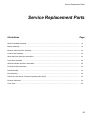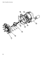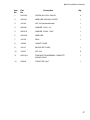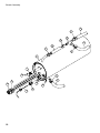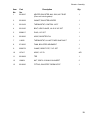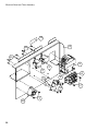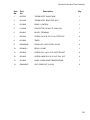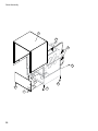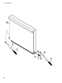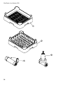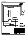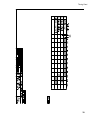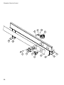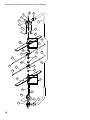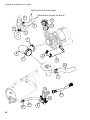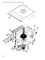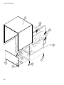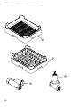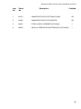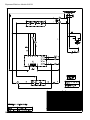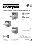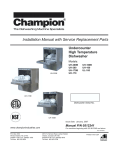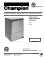
1
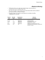
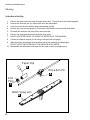
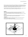
Installation/Operation Manual with Service Replacement Parts
Undercounter
High Temperature
Dishwasher
Model:
IUH 351
IUH 351
Machine Serial No.
Issue Date: 6.15.15
Manual P/N 0512961 rev. E
For machines beginning with S/N W09019166 and above
3765 Champion Boulevard
Winston-Salem, NC 27105
336/661-1992 Fax: 336/661-1660
Toll-free: 800/858-4477
2674 North Service Road, Jordan Station
Ontario, Canada L0R 1S0
905/562-4195 Fax: 905/562-4618
Toll-free: 800/263-5798
Printed in the USA
For future reference, record your dishwasher information in the box below.
Model Number__________________________ Serial Number_______________________
Voltage________________Hertz_____________ Phase__________________
Service Agent __________________________________ Tel:______________________
Parts Distributor _________________________________ Tel:______________________
National Service Department
In the U.S.A.
Toll-free: 800/ 858-4477
Tel:
336/ 661-1992
Fax: 336/ 661-1660
Email: [email protected]
ATTENTION:
The model no., serial no., voltage, Hz
and phase are needed to identify your
machine and to answer questions.
The machine data plate is located
on the lower front panel.
Please have this information ready
if you call for service assistance.
COPYRIGHT © 2015 All rights reserved
Printed in the USA
Revision History

Revision History
•
The Revision History can contain part number changes, new instructions, or
information that was not available at print time.
•
We reserve the right to make changes to these instructions without notice and without
incurring any liability by making the changes..
•
Equipment owners may request a revised manual, at no charge, by calling
1 (800) 858-4477 in the USA.
Revision
Date
Revised
Pages
Serial Number
Effectivity
8.31.09
All
W09019168
6.14.10
4
W09019168
1.21.11
15-37
W09019168
5.5.11
30-31
W09019168
6.9.11
34-35
W09019168
6.15.15
29
All
Revision
Description
Released first edition
Corrected drain type to gravity
Reformatted parts list
Changed Item 1 to 220VAC
Changed door assembly to P/N 0713141
Corrected Item No. 24 Part Numver. Changed from 0512789 to 0512879
i
Blank Page
This Page
Intentionally
Left Blank
ii
Table of Contents
_
Table of Contents
Model IUH 351 Undercounter Dishwasher
Revision History.................................................................................................................. i
Model Description............................................................................................................... iv
Installation...............................................................................................1
Receiving.....................................................................1
Electrical Connections.................................................2
Water Connections......................................................4
Drain Connections.......................................................5
Initial Start-up...........................................................................................6
Operation................................................................................................................7
Normal Wash Mode.....................................................7
Rinse Sentry Mode......................................................8
Cleaning and Maintenance........................................................................9
Cleaning.......................................................................9
Maintenance................................................................12
Troubleshooting...........................................................13
Service Replacement Parts........................................................................15
Electrical Schematic.............................................................................................. 38
Timer Chart..............................................................................................39
iii
Model Description
Model Description
IUH 351
High temperature hot water sanitizing dishwasher with built-in 40°F/22°C rise booster heater.
208-240VAC/50/60/1
iv
Installation
Receiving
NOTE:
The installation of your dishwasher must be performed by qualified service personnel.
Problems due to improper installation are not covered by the Warranty.
1.
Inspect the outside of the dishwasher carton for signs of damage.
2.
Remove the carton and inspect the dishwasher for damage.
3.
Check for any accessories that may have shipped with your dishwasher.
4.
Move the dishwasher near its permanent location.
CAUTION:
Be careful when lifting the to prevent damage.
NOTE:
The installation must comply with local health codes.
5.
Check the utility connections are the same.
6.
The dishwasher can be installed as a free-standing or under a built-in counter-top.
The typical counter-top height 34" [86cm].
7.
Place the dishwasher in its permanent location.
8.
The dishwasher has 4 adjustable feet for leveling.
9.
Level the dishwasher front-to-back and
side-to-side.
Wall
Counter-top
34"
[86cm]
Min.
Floor
3" [8cm] Min.
1
Installation
Electrical Connections
WARNING:
Electrocution or serious injury may result when working on an
energized circuit.
Disconnect power at the main breaker or service disconnect
switch before working on the circuit.
Lock-out and tag the breaker to indicate that work is being
performed on the circuit.
ATTENTION
A qualified electrician must connect the main incoming power to the dishwasher in accordance
with all local codes and regulations .
VERIFY THE CORRECT VOLTAGE IS SUPPLIED TO THE MACHINE
THE CORRECT SUPPLY VOLTAGE IS/208-240VAC/50/60/1.
(See the diagram on next page.)
Main Terminal Block
The Main Terminal Block (MTB) is located on the left-rear corner
of the electrical panel.
2
Installation
Electrical Connections
1. Refer to the connection diagram on the preceding page and the photo below:
2. Machines require a 2-wire plus ground supply which includes a current carrying neutral.
3. Power connections are made at the Main Terminal Block (MTB).
4. The MTB is located on the left-rear corner of the electrical panel behind the front access panel.
(See the illustration on the previous page.)
NOTE:
Provide a 3 foot service loop in the power cable at the back of the dishwasher for service.
To Connect Main Power to the Dishwasher:
1. Remove the lower front access panel of the dishwasher.
2. Locate the electrical mounting panel on the right-side of the machine.
Remove the retaining nut at the top of the panel that holds the panel in place.
3. Lower the panel and pull it forward to gain access the MTB.
4. Feed the power cable through the cable hole located
on the right side, as viewed from the front of the machine,
into the interior of the machine.
5. Make sure the cable passes through the cable mounting
bracket located near the front-center of the
base and secure the cable with a cable connector.
6. Connect the ground wire to the base of the dishwasher
with the ground screw provided next to the
cable mounting bracket.
7. Feed the remaining cable wires to the Main Terminal
Block and connect according to the connection
diagram to the right.
SINGLE PHASE POWER CONNECTION
208-240VAC 50/60/1
GRD
L1
L2
208-240
VAC
HOW TO CONNECT POWER
From Rear of Machine
1. Check the data plate on the front of the
dishwasher for the voltage of the machine.
2. Remove the lower-front access panel.
Cable Bracket
3. Lower the electrical component bracket.
4. Feed the power cable from the rear of the
dishwasher to the center of the machine
and through the cable bracket.
GRD
L1
To Main Terminal Block
L2
5. Connect the ground wire to the base of the
dishwasher using the ground screw located
near the bracket.
6. Feed the power leads to the terminal block.
7. Connect L1, L2 and ground.
8. Main Power connections are complete.
Route the supply cable through the cable bracket.
3
Installation
Water Connections
NOTE
Plumbing connections must comply with local plumbing and sanitary codes.
IMPORTANT
Make sure that the flexible water supply and drain hoses are not kinked.
1.
All models have a 6 ft. flexible hot water fill hose with a 3/4" NPS connector.
2.
A 1/2" or larger main incoming supply line should be installed to the dishwasher.
3.
A 1/2" or larger shut-off valve should be installed in the water supply line as close to the
dishwasher as possible for service.
4.
The pressure regulating valve, PRV, must be installed after the shut-off service valve if the
incoming flow pressure exceeds
20-22 psi.
5.
The hot water supply must provide a minimum of 140°F/60°C, measured at the dishwasher for
the 40°F/ 22°C rise booster.
6.
A water hardness of 3 grains/U.S. gal[51.3 mg/L] or less is recommended.
Drain Connections
1.
The dishwasher has a 6 ft. flexible hot water fill hose with a 3/4" NPS connector.
2.
The machine is a gravity drain.
3.
The maximum drain flow is 8 U.S. gpm /30 LPM.
4.
Make sure the drain hose does not kink. Kinks will prevent the dishwasher from draining
completely causing water to flow out the front door.
4
Blank Page
This Page
Intentionally
Left Blank
5
Initial Start-up
Check List
1.
Remove any protective film from dishwasher. Check the interior for foreign material.
2.
Make sure that the dishwasher is permanently located.
3.
Make sure that all utility connections are complete.
4.
Make sure that the flexible drain hose and the hot water fill hose are not kinked.
5.
Make sure that the sump filter is in place.
6.
Make sure that the overflow tube is installed and firmly seated in the sump.
7.
Make sure that the spray arms are in place and that they spin freely.
8.
Fully close the dishwasher door.
9.
Turn hot water supply on and check for leaks in the main water supply piping connected
to the dishwasher.
IMPORTANT
During the initial fill, adjust the PRV to ensure that the flowing pressure of the incoming water
is set to 20-22 PSI.
Install the scrap screen, overflow tube, and spray arms.
Make sure the spray arms turn freely.
6
Operation
Normal Wash Mode
Follow the instructions below to operate the dishwasher in a Normal Wash Mode. A Rinse Sentry feature
holds the dishwasher in a wash mode if the booster heater temperature is below 180ºF/82ºC.
1.
Turn the main power on at the main circuit breaker.
2.
Install the sump filter, overflow tube and spray arms.
3.
Make sure the flexible drain hose and the flexible fill hose are not kinked,
then turn the water supply on.
4.
Close the dishwasher front door.
5.
Push the dishwasher Power Switch to the ON position.The power switch will illuminate and the
machine will fill with water.
6.
Wait 15-minutes for dishwasher to reach a minimum of 150ºF/66ºC.
7.
At the beginning of the day, run 2 empty cycles before checking the final rinse
operating temperature. The first cycle will take longer to reach the proper temperature.
! ATTENTION !
If the wash temperature is low for an extended people of time, drain the machine
and refill with fresh water. Run two empty cycles and then check that the wash tank
gauge indicates 150°F/ 66°C.
8.
Load soiled wares into the dish rack. Place plates, glasses, cups and bowls in a peg rack.
Place utensils in a single layer in a flat-bottom rack. Place pots and pans in a flat-bottom rack.
Do not overload the dish racks.
9.
Slide 1 dish rack into the wash compartment making sure that wares do not interfere with the
rotating spray arms. Do not wash more than 1 dish rack at a time.
10. Close the front door fully, then press and hold the START BUTTON for 1-second. The green
in-cycle light will illuminate and the wash cycle will begin. The wash cycle time runs for
approximately 1-1/2 minutes. (continued on next page)
7
Operation
Normal Wash Mode (continued)
11. Opening the door when the dishwasher is in-cycle will stop the dishwasher. The cycle will resume
automatically when the dishwasher door is closed fully.
12. The final rinse cycle begins at the end of the wash cycle and runs for approximately 15-seconds
13. At the end of the rinse cycle, the in-cycle light will go out. Open the door and remove the clean
rack of wares. Repeat steps 8-12 for additional dish racks.
14. Refer to the Cleaning Instructions, "After Each Meal Period or every 8 Hours of Operation", on
page 9 for the procedures to drain and clean the dishwasher.
Rinse Sentry Mode
The final rinse water temperature must be a minimum of 180ºF/82ºC during the final rinse cycle to ensure
that all wares are sanitized. If for any reason, the hot water temperature in the booster tank cannot provide
this temperature, the dishwasher will enter a Rinse Sentry Mode of operation and extend the cycle time.
The Rinse Sentry changes the Normal Operation Mode as described below:
1.
The Rinse Sentry constantly monitors the water temperature inside final rinse booster.
2.
If the temperature inside the booster heater falls below 180ºF/82ºC then the Rinse Sentry
will extend the wash cycle time until the booster heater water temperature reaches the proper
temperature.
3.
The in-cycle light will remain illuminated during the Rinse Sentry Mode.
4.
An extraordinarily long wash cycle may indicate a low incoming water temperature or a
problem with the booster heater operation.
8
DO NOT REMOVE WARES UNTIL THE FINAL RINSE CYCLE HAS
SANITIZED THE WARES AND THE GREEN CYCLE LIGHT GOES OUT.
Cleaning and Maintenance
Cleaning
After Each Meal Period or every 8 Hours of Operation.
1.
Press the lighted power switch to the OFF position. The power switch light will go out.
2.
Open the door and remove the overflow tube.
3.
Inspect and clean the overflow tube rubber seal
4.
Remove the sump filter carefully to keep the soil or waste particles from falling into the sump.
5.
Clean the sump filter by rinsing with clean water.
Be sure to back-flush the filter.
Do not strike the filter against solid objects.
6.
Check the sump for foreign material and clean as required.
7.
Replace sump filter and the overflow tube.
8.
Make sure that spray arms turn freely.
9.
Close the door and turn the ON/OFF switch to ON and return to normal operation mode.
Overflow
Tube
Heating
Element
Overflow
Seal
Sump
Filter
Sump
9
Cleaning and Maintenance
Cleaning
At the End of the Day
1.
Remove the upper and lower rinse and wash spray arms. The spray arms are interchangeable.
2.
Unscrew the rinse arm pin (A). Remove the rinse arm assemblies
3.
Clean the final rinse arm nozzles using a small paper clip (B).
4.
Remove the rinse arm end plugs (C) if necessary, and flush the rinse arm with clean water.
5.
Re-install the rinse arm end plugs if they were removed.
6.
Remove the wash spray arms and flush with clean water.
7.
DO NOT USE STEEL WOOL TO CLEAN THE INTERIOR OF THE MACHINE.
8.
Contact the chemical supplier for de-liming if required (see next page).
9.
Wipe the interior and exterior of the machine with a soft cloth and a mild detergent.
DO NOT HOSE THE EXTERIOR OF THE MACHINE WITH WATER.
10. Reassemble the dishwasher and leave the door open to allow overnight drying.
Paper Clip
B
End
Plug
C
Wash Spray arm
D
10
Rinse Arm Pin
A
Cleaning and Maintenance
De-liming
Minerals accumulate on the interior surfaces of the dishwasher. The deposits have a white haze
and, in cases of heavy accumulation, may appear as a granular solid. The generic name for mineral
deposits is lime. The removal of lime deposits is called de-liming. Your dishwasher should be delimed regularly; how often will depend on the mineral content of your water.
Inspect your machine interior for lime deposits. If deliming is required, a de-liming agent should be
used for best results in accordance with the chemical supplier's instructions.
DANGER:
Death or serious injury may result when de-liming solution is mixed with sodium hypochlorite
(chlorine bleach) sanitizing agent. Mixing may cause hazardous gases to form.
De-liming solution and other acids must never be mixed with chlorine, iodine, bromine, or fluorine.
CAUTION:
Skin contact with de-liming solutions can cause severe irritation and possible chemical burns.
Always wear protective clothing and googles when handling chemicals.
ATTENTION:
Contact your chemical supplier for specific safety procedures and instructions for the use of
the de-liming solution supplied for the dishwasher.
De-liming solution or other chemicals are not supplied by the dishwasher manufacturer.
Overflow
Tube
Heating
Element
Overflow
Seal
Sump
Filter
Sump
11
Cleaning and Maintenance
Maintenance
Follow the maintenance schedules below to keep the dishwasher operating most efficiently.
Daily Maintenance
1.
Check all of the wash arm and rinse arm spray jets and clean as necessary.
2.
Make sure that the water supply is on and that the drain is not clogged.
3.
Make sure that dish racks are in good condition.
4.
Follow the cleaning procedures given above.
Weekly Maintenance
1. Perform Steps 1-4 in the Daily Maintenance.
2. Inspect water lines for leaks.
3. Check for water leaks underneath the dishwasher.
4. Make sure the flexible water fill and drain hoses are not kinked.
5. Make sure that the dishwasher is level.
6. Clean accumulated lime deposits from the wash tank heating element.
7. Inspect the scrap screen and replace it if damaged.
8. Check the spray arms and replace or repair if damaged.
12
Troubleshooting
Troubleshooting
Follow the troubleshooting guide below in the event that your dishwasher does not operate as
expected. Perform the basic checks below before calling an authorized service agent:
1.
Make sure that the main water supply is turned on.
2.
Make sure that the main power is turned on.
3.
Make sure that the flexible water fill and drain hoses are not kinked.
Condition
Cause
Solution
Dishwasher will not run.
Door not closed.
Main power OFF.
Dishwasher OFF.
Close door completely.
Check breaker on panel.
Turn dishwasher ON.
Low or no water.
Main water supply off.
PRV setting incorrect
Solenoid strainer clogged.
Solenoid valve defective.
Open supply valve.
Adjust the PRV setting
Clean strainer.
Contact Service Agent.
Chemicals won’t feed into
dishwasher.
Chemical supply low.
Pick-up tube clogged
Supply tubing damaged.
Supply tubing kinked.
Refill chemical container.
Clean/replace tube.
Replace tubing.
Straighten tubing.
Poor wash results.
Wares incorrectly loaded.
in dishrack.
Reposition wares or
reduce amount of wares.
Clogged sump filter.
Clogged spray arms.
Clean sump filter.
Clean spray arms.
Detergent injector not
feeding.
Replace squeeze tube or
clean tubing and pick-up
tube.
Thermostat defective.
Contact Service Agent.
Detergent motor defective.
Contact Service Agent
Water temperature low.
Drain and refill wash tank
and run 2 empty cycles.
Contact service agent if
problem persists.
Safe-T-Temp extends wash
mode to allow final rinse
water booster temperature
to reach 180˚F/82˚C.
Dishwasher is operating in
the Extended Wash Mode.
Contact Service Agent
because booster
thermostat is defective.
Dishwasher stays in
wash cycle.
Press the Extended Wash
button 1 time. The Extended
Wash Indicator light will go
out, the wash cycle will
resume where it left off and
perform a final rinse cycle.
13
Blank Page
This Page
Intentionally
Left Blank
14
Service Replacement Parts
Service Replacement Parts
IllustrationsPage
Wash Pump/Motor Assembly.................................................................................................................................. 16
Booster Assembly.................................................................................................................................................... 18
Electrical Panel and Timer Assembly...................................................................................................................... 20
Control Panel Assembly.......................................................................................................................................... 22
Wash and Rinse Spray Arm Assemblies................................................................................................................. 24
Lower Hose Assembly............................................................................................................................................. 26
Wash Tank Heater and Drain Assemblies............................................................................................................... 28
Fill Solenoid Valve Assembly................................................................................................................................... 30
Panel Assembly....................................................................................................................................................... 32
Door Assembly........................................................................................................................................................ 34
Dish racks, Line Strainer, Pressure Regulating Valve (PRV) ................................................................................. 36
Electrical Schematic................................................................................................................................................ 38
Timer Chart.............................................................................................................................................................. 49
15
Wash Pump/Motor Assembly
10
11
12
9
7
8
5
4
3
6
2
1
16
Wash Pump/Motor Assembly
ItemPart
No.No.
Description
Qty.
1
0512340
SCREW, M4, PHIL, PAN HD.
9
2
0512341
IMPELLER HOUSING COVER
1
3
114144
NUT, M6 (left-hand thread)
1
4
0501501
WASHER, LOCK, 1/4"
1
5
0501478
WASHER, PLAIN, 17/64"
1
60512345
IMPELLER
1
7114139
SEAL
1
8
9
110285
GASKET, PUMP
114137
BACKPLATE, PUMP
1
10
107337
NUT, M4
9
11
0512101-1
PUMP/MOTOR ASSEMBLY COMPLETE
220VAC 50/60/1
1
12
CAPACITOR 16μF
1
H29043
17
Booster Assembly
10
9
11
9
10
10
9
9
8
7
12
9
6
2
4
1
5
13
3
18
Booster Assembly
ItemPart
No.No.
Description
Qty.
1
0512847
HEATER, BOOSTER 4kW, 208V, 40°F RISE
(Does not include gasket)
1
2
0512928
GASKET, BOOSTER HEATER 1
3
0512108
THERMOSTAT, CONTROL 195°F
1
4
0512185
BOLT, HEX FLANGE, 1/4-20 X 3/8" SST
1
5
0508817
PLUG, 1/8" SST
1
6
0512926
HOSE, BOOSTER FILL 1
7
110562
THERMOSTAT, HI-LIMIT FIXED SNAP 240°F
1
8
0712835
TANK, BOOSTER WELDMENT
1
9
0503679
CLAMP, GEAR-TYPE, 7/16" SST
5
10
107417
HOSE, 1/2" ID
A/R
110512968
TEE
1
12
108954
NUT, GRIP 6-32 W/NYLON INSERT
2
13
0512920
FITTING, BOOSTER THERMOSTAT
1
19
Electrical Panel and Timer Assembly
13
4
12
11
5
2
3
6
9
8
7
14
7
10
20
Electrical Panel and Timer Assembly
ItemPart
No.No.
Description
Qty.
1
0507323
THERMOSTAT, WASH TANK
1
3
0512108
THERMOSTAT, BOOSTER 195°F
1
4
0312909
PANEL, CONTROL
1
5
C120444
CONTACTOR, 25/40A, 3P, 220V COIL
1
6
0504951
BLOCK, TERMINAL
1
7
0503745
SCREW, RH 8-32 X 3/16" SLOTTED SST
4
80512969
TIMER
1
9
CM0082006
STAND-OFF, CIRCUIT BD. NYLON
4
10
0509428-1
RELAY, 15 AMP
1
11
0503620
SCREW, RH, 4-40 X 3/16" SLOTTED SST
4
12
0501450
SCREW, NIBS RH 6-32 X 3/16" PHIL. SST
4
13
0512934
LABEL, WASH-RINSE TEMPERATURE
1
14
CM0082007
CAP, STAND-OFF, NYLON
4
21
Control Panel Assembly
9
10
8
12
11
13
7
6
4
1
2
3
22
12
13
Control Panel Assembly
ItemPart
No.No.
Description
Qty.
1
0312959
PANEL, FACIA, IUH 351
1
2
0512958
LABEL, FACIA, IUH-351
1
3
0513075
SWITCH, ROCKER DPDT 250V NEON IUH 351
1
4
0512216
CONTACT, MOMENTARY, N.O.
2
5
0512217
HOUSING, SWITCH
2
6
0512218
BUTTON, SWITCH (GREEN)
1
7
0512232
LIGHT, INDICATOR LED, 2VDC (GREEN)
1
8
H160121
HOSE, 4.1 ft / 125cm
1
9
H450134
CLIP, HOSE
2
10
109835
SCREW, #8 1/2" PAN PHIL. T/A SELF-TAPPING
1
11
H31171
SWITCH, PRESSURE
1
12
0501408
SCREW, TRUSS SLOT., 8-32 X 1/4" SST
2
13
0512320
GASKET, STEAM
2
23
Wash and Rinse Spray Arm Assemblies
5
6
4
3
2
7
1
13
14
15
22
12
8
24
22
21
19
23
20
18
22
20
19
21
24
22
12
8
16
17
10
9
11
24
6
Wash and Rinse Spray Arm Assemblies
ItemPart
No.No.
Description
Qty.
1
0501478
WASHER, 17/64 id X 9/16" OD SST
4
2
107967
NUT, HEX 1/40-20 NYLON INSERT SST
4
3
H35509
HUB, UPPER WASH ARM
1
4
107873
WASHER, PACKING
1
5
110215
SCREW, RETAINING
1
6
0502571
CLAMP, HOSE GEAR 1-1/2" SST
2
7
0512120
HOSE, UPPER WASH ARM
1
8*
0712749
BEARING ASSEMBLY
2
9
0512133
O-RING, 2-1/8" OD X 1-3/4" ID X 3/16" 1
10
0512066
HUB, LOWER WASH ARM
1
11
0512918
MANIFOLD, LOWER FWR
1
12
H420548
WASH ARM ASSEMBLY (Includes Item 8) 2
13
0512133
O-RING, 2-1/8" OD X 1-3/4" ID X 3/16" 1
14
0501481
WASHER, NYLITE
4
15
100738
BOLT, 1/4-20 X 1" SST
4
16
0512124
SHAFT, LOWER
1
170512239
O-RING
1
18
0312840
HUB, RINSE ARM, MOLDED
2
19
0501408
SCREW, TRUSS SLOTTED 8-32 X 1/4" SST
4
20
0512841
ARM, RIGHT-HAND RINSE (7 JETS)
2
21
0512842
ARM, LEFT-HAND RINSE (8 JETS)
2
22
0512843
CAP, RINSE ARM, 5/16-24
4
23
H36275
SPINDLE, RINSE ARM
2
24
H34998
SPACER, NUT
2
---
0712834
RINSE ARM ASSEMBLY (Includes Items 18-24)2
* Note:
The bearing assembly, P/N 0712749 includes 2 bearings, 1 locknut, and 1 wash arm hub.
The bearings, locknut and hub are not available as separate service replacement parts.
25
Lower Hose Assembly
From Final Rinse Tee
To upper washarm hub
1
5
4
6
2
3
7
8
8
7
9
10
1
11
12
14
26
13
8
Lower Hose Assembly
ItemPart
No.No.
Description
Qty.
1
0502563
CLAMP, HOSE GEAR-TYPE 1" SST
2
2
107417
HOSE, RUBBER 1/2" id X .84" OD
A/R
3
0503679
CLAMP, HOSE GEAR-TYPE
1
4
0512120
HOSE, UPPER WASH
1
5
0512119
HOSE, DISCHARGE, WASH PUMP
1
6
0502571
CLAMP, HOSE GEAR-TYPE1-1/2" SST
2
7
0512322
CLAMP, HOSE GEAR-TYPE 1-13/16" -2/34" MAX SST
2
8
0512885
HOSE, SUCTION, WASH PUMP
1
9
0312144
BRACKET, WASH PUMP
1
10
0502668
HOSE, DRAIN PUMP SUCTION
1
11
0512925
HOSE, FILL 1/2" X 7' C/W FNPS
1
12
0512936
WASHER, SILICON 5/8" ID X 7/8" OD
1
13
0512926
HOSE BOOSTER FILL 1/2" X 1'
1
14
0502572
CLAMP, HOSE GEAR-TYPE 5/16"
1
27
Wash Tank Heater and Drain Assembly
1
21
25
22
24
23
20
2
19
3
4
5
6
7
8
2
3
9
18
3
10
4
11
10
12
17
13 14 15
16
28
4
Wash Tank Heater and Drain Assembly
ItemPart
No.No.
Description
Qty.
1
0512930
GASKET, DOOR
1
2
0512846
HEATER, WASH TANK, 2KW, 240VAC
1
3
100003
WASHER, SPLIT LOCK 1/4" SST
4
4
0501539
NUT, HEX 1/4-20 SST
4
50501836
O-RING
2
6
0508873
ADAPTER, THERMOSTAT
1
7
0512920
BUSHING, THERMOSTAT
1
8
0507323
THERMOSTAT, WASH TANK
1
9
201029
NUT, LOCK 1/2" NICKLE-PLATED
2
10
108954
NUT, GRIP 6-32 W/NYLON INSERT
4
11
113604
THERMOSTAT, FIXED, SNAP 212°F
1
12
0501437
SCREW, 4-40 X 1/2" SST
2
13
0501379
SWITCH, DOOR 15 AMP
1
14
0309228
BRACKET, SWITCH
1
15
0312605
PLATE, SWITCH NUT
1
16
D500605
ELBOW, PUMP SUCTION
1
17
D80208
GASKET, PUMP SUCTION
1
18
D540088
FLANGE, PUMP SUCTION
1
19
H250110
TRAP. AIR
1
20
H25263
GASKET, FLAT
1
21H25239
O-RING
1
22
H25011
COVER, AIR TRAP
1
23
0512845
FILTER, SUMP
1
SEAL, OVERFLOW TUBE
1
TUBE, OVERFLOW
1
24
0512879
25
0512844
29
Fill Solenoid Valve Assembly
1
2
3
4
30
Fill Solenoid Valve Assembly
ItemPart
No.No.
Description
Qty.
1
0512853-1
VALVE, WATER INLET 220VAC/60/1
(Includes Item 2)
1
2
0512860
KIT, REPAIR SOLENOID VALVE
A/R
3
0512185
BOLT, HEX FLANGE 1/4-20 X 3/8" SST
2
4
0312893
BRACKET, VALVE
1
31
Panel Assembly
1
6
6
4
2
3
4
5
4
32
5
Panel Assembly
ItemPart
No.No.
Description
Qty.
1
0312905
WRAP, OUTER PANEL
1
2
0503718
FOOT, ADJUSTING
4
3
0312960
PANEL, FRONT IUH 351
1
4
100007
SCREW TRUSS SLOT SS 10-32X3/8
4
5
0503718
ADJUSTING, FOOT
4
6
0512761
CLAMP, DOUBLE CONDUIT
3
33
Door Assembly
1
2
3
2
4
5
34
3
Door Assembly
ItemPart
No.No.
Description
Qty.
1
0713141
DOOR WELDED ASSY
1
2
0312892
ARM, DOOR SPRING
2
3
0512854
SPRING, DOOR
2
4
0312908
ACTUATOR, DOOR SWITCH
1
5
0503745
SCREW, 8-32 X 3/16" PHIL. SST
2
35
Dish Racks, Line Strainer, PRV
1
2
4
3
36
Dish Racks, Line Strainer, PRV
ItemPart
No.No.
Description
Qty.
1
101273
2
101285
3
104421
DISH RACK, FLAT-BOTTOM
AR
DISH RACK, PEG
AR
STRAINER, LINE 1/2" BRONZE (OPTIONAL)
1
4
VALVE, PRESSURE REGULATING (PRV) (OPTIONAL)
1
108265
37
Electrical Schematic
38
Timing Chart
39
Español
Manual de Español
40
Instalación Y Operación, Manual de Servicio y Partes de Reemplazo
Lavadora de Platos
Bajo Barra
De Alta Temperatura
Modelo:
IUH 351
IUH 351
Maquina Número de Serie.
Fecha Expedición: 6.15.15
Manual P/N 0512961 rev. E
para máquinas que empiezan con S/N W09019166 y arriba
3765 Champion Boulevard
Winston-Salem, NC 27105
336/661-1992 Fax: 336/661-1660
Toll-free: 800/858-4477
2674 North Service Road, Jordan Station
Ontario, Canada L0R 1S0
905/562-4195 Fax: 905/562-4618
Toll-free: 800/263-5798
Impreso en los EE. UU.
Para futuras referencias, escribir la infomaciόn de su lavadora de platos in el cuadro abajo.
Numero de Modelo__________________________ Numero de Serial_______________________
Voltaje________________Frecuencia_____________ Fase__________________
Servicio __________________________________ Tel:______________________
Distribuidor _________________________________ Tel:______________________
Departmento de Servicio Nacional en los EE.UU.
Toll-free: 800/ 858-4477
Tel:
336/ 661-1992
Fax: 336/ 661-1660
Email: [email protected]
ATENCIÓN:
Nú.de modelo, Nú de serial, voltaje, Hz
y fase se necesitan para identificar su
máquina y para responder sus preguntas.
La placa de datos de la máquina se
encuentra en el panel frontal inferior.
Por favor tenga esta información lista
al momento de llamar al servicio de
asistencia.
COPYRIGHT © 2015 Todo derecho Reservado
Impreso en los EE. UU.
Historial de Revisiones

Fecha de Revisiόn
Revisiόn de Páginas
Historial de Revisions
Effectividad de
numero de serie
8.31.09Todas
6.14.10
4
1.21.11
15-37
5.5. 11
30-31
6.9.11
34-35
W09019166
W09019166
W09019166
W09019166
W09019166
Descripciόn
de la Revisiones
Primero Ediciόn
La máquina tiene un drenaje de gravedad
Para formatear la lista de partes
Cambie artículo 1 a 220VAC
Cambie ensamble de la Puerta a P/N 0713141
i
Página en Blanco
Esta Página
Intencionalmente se ha
Dejado en Blanco
ii
Indice de Contenidos
Indice de Contenidos
Model IUH 351 Lavaplatos Bajo Barra
Historial de Revisiones........................................................................................................ i
Descripciόn de Modelo........................................................................................................ iv
Instalaciόn...............................................................................................1
Recibir..........................................................................1
Conexiones Eléctricas.................................................2
Conexiones de agua....................................................4
Conexiones de desagüe..............................................5
Arranque Inicial........................................................................................6
Montaje........................................................................ 8
Funcionamiento......................................................................................................7
Modo de Lavado Normal.............................................7
Modo de Enjuague Centinela......................................8
Limpieza Y Mantenimiento.........................................................................9
Limpieza......................................................................9
Mantenimiento.............................................................12
Localizaciόn Y Soluciόn De Problemas.......................13
Servicio, Partes De Reemplazo..................................................................15
Esquemas Eléctricos............................................................................................. 38
Gráficas para Medidor de Tiempos.............................................................39
iii
Descripciόn de Modelo
Descripciόn de Modelo
351HT E
El lavaplatos esterilizador de alta temperatura con agua caliente, está construido con
temperatura de calefacción de refuerzo integrado 40°F/22°C aumento.
208-240VAC/50/60/1.
iv
Instalación
Recibir
ATENCIÓN:
La instalación de su lavaplatos debe realizarse por una persona de servicio calificado.
Problemas debido a la instalación incorrecta de su equipo no serán cubiertos por la garantía.
1.
2.
3.
4.
Inspeccionar el exterior de la caja de cartón de su lavaplatos por si tiene muestras de daño.
Quitar la caja de cartón e inspeccionar el lavaplatos por daños.
Buscar todos los accesorios que pueden haber sido enviadas con su lavaplatos.
Mueva el lavaplatos cerca de la ubicación permanente.
PRECAUCIÓN:
Tenga cuidado al levantarla para evitar daños.
ATENCIÓN:
La instalación debe cumplir con códigos de salud local.
5. Compruebe que las conexiones de utilidad sean los mismos.
6. El lavaplatos puede instalarse como un lavaplatos independiente o en virtud de uno bajo barra.
La altura típica de uno bajo barra es 34" [86cm].
7. Coloque el lavaplatos en su ubicación permanente.
8. El lavaplatos tiene 4 pies ajustables de nivelación.
9. Nivelar el lavaplatos alfrente y atrás, y lado a lado.
Pared
Barra
34"
[86cm]
Min.
Piso
3" [8cm] Min.
1
Instalación
Conexiones Eléctricas
ADVERTENCIA:
Electrocución o lesiones serias pueden resultar cuando
se trabaja con un circuito de energía. Desconecte la energía
en el interruptor principal o de servicio de interruptores y
desconéctelo antes de trabajar en el circuito. Mirar y marcar
el interruptor para indicar que esta trabajando con
ese circuito.
ATENCIÓN
Un electricista calificado debe ser quien conecte la entrada de energía del lavaplatos de
acuerdo con las regulaciones de conformidad con todos los códigos reglamentarios locales.
VERIFICAR EL VOLTAJE CORRECTO QUE SE ESTA SUMINISTRANDO A LA MAQUINA
EL SUMINISTRO DE VOLTAGE CORRECTO ES 208 - 240 VCA/50/60/1.
(Vea el diagrama en la página siguiente.)
El Bloque Principal, Terminal Eléctrico
El bloque principal, terminal eléctrico (MTB) se encuentra en la esquina trasera izquierda del panel eléctrico.
2
Instalación
Conexiones Eléctricas
1. Consulte el diagrama de conexión en la página anterior y en la foto debajo:
2. Máquinas requieren 2 abastecimientos, uno de tierra y uno que incluye un cable de transporte de
corriente neutral.
3. Las conexiones de energía se realizan en el bloque principal del terminal (MTB).
4. El MTB se encuentra en la esquina trasera izquierda del panel eléctrico detrás del panel frontal de
acceso. (Consulte la ilustración en la página anterior).
ATENCIÓN:
Proporcionar 3 pies de cable de energía eléctrica enrollado en la parte trasera del lavaplatos para el servicio.
Conexión de suministro principal al lavaplatos.
1. Quitar el panel delantero de acceso al lavaplatos.
2. Busque el panel de montaje eléctrico en el lado derecho
de la máquina. Quite la tuerca de retención en la parte
superior del panel que mantiene el panel en su lugar.
3. Disminuir el panel y tire hacia adelante para acceder al
bloque principal del terminal (MTB).
4. Colocar el cable de energía eléctrico a través del agujero
de cable, localizado en el lado derecho, tal como se
puede ver en la parte frontal de la maquina, en el interior
del lavaplatos.
5. Asegúrese de que el cable pase a través del soporte
situado en el montaje cerca de la parte frontal-centro de
la base y asegurar el cable con un conectador de cable.
6. Conecte el cable de tierra a la base del lavaplatos, con el
tornillo de tierra junto al cable de soporte de montaje.
7. Los cables de energía eléctrica que sobren, deben ser
colocados con el terminal principal y conectar según el
diagrama de conexión a la derecha.
Fase Sencilla de Conexión Eléctrica
208-240VAC 50/60/1
GRD
L1
L2
208-240
VAC
Como Conectar la Electricida
1.
Desde la Parte Posterior
de la Máquina
2.
3.
Soporte de Cable
4.
5.
GRD
Bloque Terminal
L1
Eléctrico Principal
6.
L2
7.
8.
Compruebe la placa de datos en la parte
delantera del lavaplatos para los voltios de la
máquina.
Quitar la parte inferior del panel de acceso
frontal.
Disminuir el soporte de componentes
eléctricos.
Suministrar el cable eléctrico de la parte
posterior del lavaplatos en el centro de la
máquina y a través del soporte del cable
Conecte el cable de tierra a la base de
la lavadora de platos utilizando el tornillo
de tierra situado cerca del soporte.
Suministrar la luz que conduce al bloque
de terminal.
Conecte L1, L2 en el piso.
Conexiones de suministro principal
están completas.
Dirija el cable de suministro a través del soporte de cable.
3
Instalación
Conexiόn de Agua
ATENCIÓN
Conexiones de plomería deben cumplir con plomería local y cόdigos sanitarios.
IMPORTANTE
Asegúrese de que el suministro de agua y tubos flexibles de drenaje no estén torcidos.
1. Todos los modelos cuentan con una manguera de agua caliente de 6 pies, y con un
conectador de NPS 3/4".
2. Un 1/2" o una mas grande línea principal de suministro entrante debe ser instalado en el
lavaplatos.
3. Un 1/2" o una más grande válvula de cierre debe ser instalado en la línea de suministro de
agua lo mas cerca posible para poder darle un buen servicio al lavaplatos.
4. La válvula reguladora de presión, PRV, debe instalarse después que la válvula de cierre de
servicio este apagada, Si la entrante es bajo la presión que no sea superior a 20-22 psi.
5. El suministro de agua caliente debe proporcionar un mínimo de 140°F/60°C,
Medir en el lavaplatos para el calentador de agua de 40°F / de 22°C.
6. Dureza de agua de 3 granos/U.S. gal [51.3mg/L] o menos es recomendado.
Conexiόn de Desagüe
4
1.
El lavaplatos tiene una manga de desagüe de gravedad.
2.
El flujo máximo de desagüe es 8 (E.U.) galones por minuto/30 litros por minuto.
3.
Asegúrese de que la manga de desagüe no tiene retorcedura. Las retorceduras
prevendrán el agua de desaguar completamente, y el lavaplatos se derramará
fuera la puerta principal.
Página en Blanco
Esta Página
Intencionalmente se ha
Dejado en Blanco
5
Arranque Inicial
Lista de Verificaciόn
1. Quitar cualquier protector del lavaplatos. Revise el interior por cualquier material extraño.
2. Asegúrese el lavaplatos esté permanentemente en su sitio.
3. Asegúrese todas las conexiones de servicios públicos están completos.
4. Asegúrese el conducto de drenaje extendido y la manguera de agua caliente no estén enredadas.
5. Asegúrese el filtro de el sifón este en su lugar.
6. Asegúrese el tubo de desagüe está instalado y bien puesto firmemente en el sifón.
7. Asegúrese los brazos rociadores están en su lugar y que giren libremente.
8. Totalmente cerrar la puerta del lavaplatos.
9. Gire el suministro de agua caliente y comprobar si hay fugas en el suministro de agua principal
conectados a la tubería del lavaplatos.
IMPORTANTE
Durante el relleno inicial, ajuste la PRV para garantizar que la presión que fluye
el agua entrante este establecida en 20-22 psi.
Instale el filtro del sifón, tubo de desbordamiento, y los brazos de rociado.
Asegúrese de que los brazos de rociado giren libremente.
6
Operación
Modo de Lavar Normal
Siga las siguientes instrucciones para hacer funcionar el lavaplatos en un modo normal. Una
característica de enjuague Centinela mantiene el lavaplatos lavando si el calentador de agua esta
por debajo de 180ºF/82ºC.
1. Gire el interruptor principal que esta en el circuito principal.
2. Instalar el filtro del sifón, sobre el tubo de desagüe y los brazos rociadores.
3. Asegúrese de que la manguera de drenaje flexible y la manguera extensible del agua no
estén torcidas o enredadas, y encienda el abastecimiento de agua.
4. Cierre la puerta de entrada del lavaplatos.
5. Presione el interruptor de encendido de lavaplatos a la posición ON. El interruptor de
encendido se iluminará, la máquina empezará a llenarse con agua.
6. Espere 15 minutos para que el lavaplatos llegue a un mínimo de150ºF/66ºC.
7. Colocar platos sucios en el estante para platos. Coloque platos, vasos, tazas, y platos hondos
en una canasta de soporte. Coloque utensilios en una sola capa y acostados al fondo de
una canasta. Coloque ollas y sartenes en una canasta plana en el fondo de la misma. No
sobrecargue las canastas de platos.
8. Deslice 1 estante para platos en el compartimiento de lavado, asegurándose de que los
platos no toquen o interfieran con los brazos de rociado en rotación. No lavar mas de una
canasta a le vez.
9. Cerrar la puerta delantera plenamente, a continuación, presione y sostenga el interruptor de
encendido (Start) por un segundo. Se encenderá la luz en el ciclo de color verde y se iniciará
el ciclo de lavado. El ciclo de lavado tendrá un tiempo de duración aproximadamente 1-1/2
minutos.
10.Al abrir la puerta cuando el lavaplatos esta encendido la maquina automáticamente se
apagara. El ciclo se reanudará automáticamente cuando la puerta del lavaplatos se cierra
completamente.
11.El ciclo de enjuague comienza al final del ciclo de lavado y tiene una duración
aproximadamente 15 segundos.
12.Al final del ciclo de enjuague, la luz del ciclo se apagará, Abra la puerta y sacar la bandeja de
los platos limpios. Repita los pasos del 8-12 para canastas de platos adicionales.
13.Consulte las instrucciones de limpieza, "Después de cada periodo de comida o cada 8 horas
de funcionamiento", en la página 9 para los procedimientos drenaje y limpieza del lavaplatos.
7
Operación
Modo de Enjuague Centinela
La temperatura del agua de enjuague final debe ser de un mínimo de 180ºF/82ºC durante el ciclo de
enjuague final para garantizar que todos los productos sean desinfectados. Si por cualquier motivo,
la temperatura del agua caliente en el tanque de calentador de agua no puede proporcionar esta
temperatura, el lavaplatos entra en el ciclo en modo de centinela y se extiende el tiempo de operación.
El enjuague centinela cambia el modo de operación normal, tal como se describe a continuación:
1. El centinela enjuague supervisa constantemente la temperatura del agua dentro del calentador de
agua en el enjuague final.
2. Si la temperatura dentro del calentador de agua cae por debajo de los 180ºF/82ºC entonces el
enjuague centinela ampliará el ciclo de lavado de tiempo hasta que la temperatura del agua del
calentador alcance la temperatura adecuada.
3. La luz permanecerá encendida durante el modo de enjuague de centinela.
4. Un ciclo de lavado extraordinariamente largo puede indicar una baja temperatura del agua entrante o
un problema con el funcionamiento del calentador de agua.
NO QUITE LOS PLATOS HASTA QUE EL CICLO DE ENJUAGUE FINAL HAYA
DESINFECTADO Y LA LUZ VERDE DEL CICLO FINAL SE HAYA APAGADO.
! ATENCIÓN !
Si la temperatura de lavado esta baja por un tiempo extendido, drene la maquina y
rellene con agua fresca. Inicié dos ciclos de lavado (sin platos o vasos en la maquina) y
chequear que el termómetro del tanque de lavado indique 150°F/66°C.
8
La Limpieza Y Mantenimiento
Limpieza
Después de cada periodo de comida o cada 8 horas de funcionamiento
1.
Presione el interruptor de encendido en la posición OFF. El interruptor de luz de encendido se
apagara.
2.
Abra la puerta y retire el tubo de desagüe.
3.
Quite el filtro del sifón con cuidado para mantener las partículas o residuos de comida, para que no
caigan dentro del sifón.
4.
Limpie el filtro del sifón y enjágüelo con agua limpia.
Asegúrese de lavar el filtro por ambos lados.
No golpear el filtro contra objetos sólidos.
5.
Revise el sifón por si quedo algún material extraño o comida y límpielo según sea necesario.
6.
Reemplazar el filtro del sifón y el tubo de desagüe.
7.
Asegúrese de que los brazos de rociado giren libremente.
8.
Cerrar la puerta y prender el interruptor de encendido ON/OFF (PRENDER/APAGAR) a ON y
volver al modo de funcionamiento normal.
Tubo de Desagüe
Resistencia de
Calefacción
Sello para el Tubo
de Desagüe
Filtro Del
Sifón
Sifón
9
La Limpieza Y Mantenimiento
Limpieza
Al final del día
1. Retire los brazos rociadores inferior y superior de enjuague y de lavado, Los brazos de rociado son
intercambiables.
2. Afloje el pin del brazo de enjuague (A). Quitar los brazos de enjuague ensamblables.
3. Limpiar las boquillas de brazo de enjuague final con un pequeño clip de papel (B).
4. Quite los tapones de los brazo de enjuague final (C) si es necesario, y lavar el brazo
de enjuague con agua limpia.
5. Vuelva a instalar los tapones de enjuague final del brazo si se quitan.
6. Quitar los brazos rociadores de lavado y lavarlos con agua limpia.
7. NO UTILICE ESPONJA DE ACERO PARA LIMPIAR EL INTERIOR DE LA MÁQUINA.
8. Póngase en contacto con el proveedor de productos químico para de-calcificar si es necesario
(consulte la página siguiente).
9. Limpiar dentro y fuera de la máquina con un paño suave y un detergente suave.
NO LAVE POR FUERA DE LA MÁQUINA CON UNA MANGUERA Y AGUA.
10.Volver a ensamblar el lavaplatos y dejar la puerta abierta para permitir que se seque durante la noche.
Clip de Papel
B
Tapón
Final
C
Brazo Rociador
de Lavado
D
10
Clavija para el
Brazo de Enjuague
A
La Limpieza Y Mantenimiento
Para Descalcificar
Minerales se acumulan en las superficies interiores del lavaplatos. Los depósitos tienen una niebla
blanca y, en los casos de acumulación pesada, pueden aparecer como gránulos sólidos.
El nombre genérico para depósitos minerales es CAL. La eliminación de los depósitos de CAL se
denomina de - calcificar. Su lavaplatos debe ser de – calcificar regularmente; y con qué frecuencia
dependerá de el contenido de su agua mineral.
Inspeccionar el interior de máquina para depósitos de cal. Si se requiere de - calcificar, un químico
para de – calcificar debe utilizarse para obtener mejores resultados de conformidad con las
instrucciones del proveedor de productos químicos.
Peligro:
Pueden ocasionar la muerte o lesiones graves cuando de - calcificar solución se mezcla con
hipoclorito de sodio (blanqueador de cloro) un químico de limpieza. Mezclarlos puede causar gases
peligrosos. La solución de decalcificando y otros ácidos nunca deben ser mezclada con yodo, cloro,
bromo o flúor.
Precaución:
Contacto con la piel de las soluciones de cal puede causar irritación severa y posibles quemaduras
químicas. Siempre use ropa protectora y gafas al manipular los productos químicos.
Atención:
Comuníquese con su proveedor de sustancias químicas para los procedimientos específicos de
seguridad y las instrucciones para el uso de la solución de-calcificar, suministrados para el
lavaplatos. La solución para Decalcificar, o otros químicos no se pueden conseguir con la fabrica
de lavaplatos.
Tubo de Desagüe
Resistencia de
Calefacción
Sello para el Tubo
de Desagüe
Filtro Del
Sifón
Sifón
11
La Limpieza Y Mantenimiento
Mantenimiento
Follow the maintenance schedules below to keep the dishwasher operating most efficiently.
Siga los planos de mantenimiento mencionados abajo para mantener el lavaplatos en un funcionamiento
más eficiente.
Mantenimiento diario
1. Mirar todos los Brazos de lavado y enjuague y los inyectores de roseo, limpiarlos si es necesario.
2. Asegúrese de que el suministro de agua estén encendidos y que el desagüe no esté obstruido.
3. Asegúrese de que las canastas de platos estén en buenas condiciones.
4. Siga los procedimientos de limpieza dados anteriormente.
Mantenimiento Semanal
1. Realicé los pasos 1-4 en el mantenimiento diario.
2. Inspeccionar las mangueras de agua por si hay una fuga.
3. Asegurase que no haya fugas de agua por debajo del lavaplatos.
4. Asegúrese de que la manguera de agua y de desagüe extensible no estén torcidas.
5. Asegúrese de que el lavaplatos esta en nivel.
6. Limpiar los depósitos de cal acumulados en la resistencia del tanque de lavado.
7. Inspeccione los filtros de desperdicios y reemplazarlos si están dañados.
8. Mirar los brazos de rociado y reemplazar o reparar si están dañados.
12
Localizaciόn y Soluciόn de Problemas
Localizaciόn y Soluciόn de Problemas
Siga la guía de solución de problemas más adelante en caso de que su lavaplatos no funcione
como se espera. Chequear los controles básicos a continuación antes de llamar a un agente de
servicio técnico autorizado.
1. Asegúrese el suministro principal de agua está activado
2. Asegúrese el interruptor principal está encendido.
3. Asegúrese la manguera de agua y de desagüe extensible no estén torcidas
CONDICIÓN
El lavaplatos no se pone
en marcha
CAUSA
La puerta no cierra.
Interruptor principal
encendido apagado.
Lavaplatos apagado.
.
SOLUCIÓN
Cerrar la puerta.
Verifica que el interruptor
de luz principal este
encendido.
Prender el lavaplatos.
No hay agua o hay poco
agua
Suministro principal de
agua está apagado.
PRV configuración
incorrecta.
Solenoide filtro obstruido.
Solenoide de la válvula
defectuosa..
Abra la válvula de
suministro.
Adjustar la configuración
PRV.
Limpiar el filtro.
Póngase en contacto con
el agente de servicio.
Resultados muy bajos
de lavado.
El tanque no tiene
detergente.
Platos incorrectamente
puestos en la conasta de
platos.
Añadir detergente.
Filtro del sifón obstruido.
Brazos de rociado
obstruidos.
Limpiar el filtro de sifón.
Limpiar loas brazos de
rociado.
Termostato defectuoso.
Póngase en contacto con
el agente de servicio.
Motor de detergente
defectuoso.
Póngase en contacto con
el agente de servicio.
Organizar los platos o
reducir la cantidad de
platos.
La temperatura del agua de Póngase en contacto con
lavado es demasiado baja. el agente de servicio.
Lavaplatos debe estar en
el ciclo de lavado.
Enjuague centinela
ampliará el tiempo hasta
que la temperatura del
agua del calentador alcance
la temperatura adecuada
180˚F/82˚C.
Póngase en contacto con
el agente de servicio.
porque el motor del
termostato esta
defectuoso.
13
Página En Blanco
Esta Página
Intencionalmente se ha
Dejado en Blanco
14
Repuestos de Servicio
Respuestos de Servicio
IllustacionesPágina
Motor/Bomba Para Lavar........................................................................................................................................ 16
Calentador Eléctrico................................................................................................................................................ 18
Panel Eléctrico y Temporizador............................................................................................................................... 20
Panel de Control...................................................................................................................................................... 22
Montaje de los Brazos Rociadores para Lavar y Enjugar....................................................................................... 24
Montaje de los Mangueras de abajo....................................................................................................................... 26
Calefacciόn para el Tanque de Lavado y Montaje del Sifόn.................................................................................... 28
Montaje de la Válvula Solenoide para Rellenar...................................................................................................... 30
Montaje del Panel.................................................................................................................................................... 32
Montaje de la puerta................................................................................................................................................ 34
Bandeja de Platos, Filtro de Linea y Reguladora de Presiόn ................................................................................. 36
Esquema Eléctrico.................................................................................................................................................. 38
Temporizador Gráfico.............................................................................................................................................. 39
15
Motor/Bomba Para Lavar
10
11
12
9
7
8
5
4
3
6
2
1
16
Motor/Bomba Para Lavar
ItemPartes
No.No.
Descripción
Cantidad.
1
0512340
TORNILLO, M4, PHIL, PAN HD.
9
2
0512341
TAPA PARA EL PROPULSOR
1
3
114144
TUERCA, M6 (roscas izquierdas)
1
4
0501501
ARANDELA DE CIERRE, 1/4"
1
5
0501478
ARANDELA, 17/64"
1
6
0512345
PROPULSOR
1
7
114139
SELLO
1
8
9
110285
EMPAQUE, BOMBA
114137
PLACA, BOMBA
1
10
107337
TUERCA, M4
9
11
0512101-1
BOMBA / DE MONTAJE DE MOTOR COMPLETO
220VAC 50/60/1
1
12
CAPACITOR 16μF
1
H29043
17
Calentador Eléctrico
10
9
11
9
10
10
9
9
8
7
12
9
6
2
4
1
5
13
3
18
Calentador Eléctrico
ItemPartes
No.No.
Descripción
Cantidad.
1
0512847
RESISTENCIA, CALENTADOR 4KW, 208V, 40°F
(No Incluye la Empaque)
1
2
0512928
EMPAQUE, CALENTADOR 1
3
0512108
CONTROL, TERMOSTATO 195°F
1
4
0512185
PERNO, TUERCA EXAGONAL, 1/4-20 X 3/8" SS
1
5
0508817
TAPÓN, 1/8" SST
1
6
0512926
MANGUERA, PARA LLENAR EL CALENTADOR 1
7
110562
TERMOSTATO, ALTO – LÍMITE, FIJO 240°F
1
8
0712835
TANQUE, CALENTADOR
1
9
0503679
ABRAZADERA, 7/16" SST
5
10
107417
MANGUERA, 1/2" ID
A/R
110512968
TE
1
12
108954
TUERCA, AGARRADERA DE NYLON 6-32"
2
13
0512920
UNION, TERMOSTATO DE CALENTADOR
1
19
Panel Eléctrico y Temporizador
13
4
12
11
5
2
3
6
9
8
7
14
7
10
20
Panel Eléctrico y Temporizador
ItemPartes
No.No.
Descripción
Cantidad.
1
0507323
TERMOSTATO, TANQUE DE LAVADO
1
3
0512108
TERMOSTATO, CALENTADOR 195°F
1
4
0312909
PANEL, CONTROL
1
5
C120444
CONTACTOR, 25/40A, 3P, 220V BOBINA
1
6
0504951
BLOQUE, TERMINAL
1
7
0503745
TORNILLO, RH 8-32 X 3/16" RANURA SST
4
8
0512969
TEMPORIZADOR, TARJETA DE CIRCUITO
1
9
CM0082006
SEPARADOR, TARJETA DE CIRCUITO. NYLON
4
10
0509428-1
INTERRUPTOR DE RELEVO, 15 AMP
1
11
0503620
TORNILLO, RH, 4-40 X 3/16" RANURA SST
4
12
0501450
TORNILLO, NIBS RH 6-32 X 3/16" ESTRELLA. SST
4
13
0512934
ETIQUETA, LAVADO – ENJUAGUE, TEMPERATURA
1
14CM0082007
TAPA, SEPARADOR, TARJETA DE CIRCUITO. NYLON4
21
Ensamble, Panel de Control
9
10
8
12
11
13
7
6
4
1
2
3
22
12
13
Ensamble, Panel de Control
ItemPartes
No.No.
Descripción
Cantidad.
1
0312959
PANEL, FRONTAL, IUH 351
1
2
0512958
ETIQUETA, FRONTAL, IUH 351
1
3
0513075
INTERRUPTOR DPDT 250V NEON IUH 351
1
4
0512216
CAJA, INTERRUPTORES
2
5
0512217
CAJA, INTERRUPTORES
2
6
0512218
BOTÓN, INTERRUPTOR (VERDE)
1
7
0512232
LUZ, INDICADOR LED, 2VDC (VERDE)
1
8
H160121
MANGUERA, 4.1 ft / 125cm
1
9
H450134
CLIP, MANGUERA
2
10
109835
TORNILLO, #8 1/2" ESTRELLA .T/A AUTORROSCANTE
1
11
H31171
INTERRUPTOR, DE PRESIÓN
1
12
0501408
TORNILLO, RANURA DE ARMADURA, 8-32 X 1/4" SST
2
13
0512320
EMPAQUE, VAPOR
2
23
Montaje de los Brazos Rocíadores para Lavar y Enjuagar
5
6
4
3
2
7
1
13
14
15
22
12
8
24
22
21
19
23
20
18
22
20
19
21
24
22
12
8
16
17
10
9
11
24
6
Montaje de los Brazos Rocíadores para Lavar y Enjuagar
ItemPartes
No.No.
Descripción
Cantidad.
1
0501478
ARANDELA, 17/64 id X 9/16" OD SST
4
2
107967
TUERCA, EXAGONAL 1/40-20 INSERTADO, NYLON SST
4
3
H35509
CUBO DE BRAZO DE LAVADO, ARRIBA
1
4
107873
ARANDELA, EMPAQUE 1
5
110215
TORNILLO, RETENEDOR
1
6
0502571
CLAMP, HOSE GEAR 1-1/2" SST
2
7
0512120
ABRAZADERA, MANGUERA 1-1/2" SST
1
8*
0712749
BALINERAS DE ENSAMBLE
2
9
0512133
O-ANILLO, 2-1/8" OD X 1-3/4" ID X 3/16" 1
10
0512066
CUBO DE LA BRAZO DE LAVADO, ABAJO
1
11
0512918
COLECTOR, ABAJO FWR
1
12
H420548
ENSABLE, BRAZO DE LAVADO (Incluye Item 8 ) 2
13
0512133
O-ANILLO, 2-1/8" OD X 1-3/4" ID X 3/16" 1
14
0501481
ARANDELA, NYLON
4
15
100738
TORNILLO, 1/4-20 X 1" SST
4
16
0512124
EJE, INFERIOR
1
17
0512239
O - ANILLO
1
18
0312840
CUBO, BRAZO DE ENJUAGUE, MOLDEADO
2
19
0501408
TORNILLO, RANURA DE ARMADURA 8-32 X 1/4" SST
4
20
0512841
BRAZO, MANO – DERECHA DE ROCIADO (7 CHORROS) 2
21
0512842
BRAZO, MANO - IZQUIERDA DE ROCIADO (8 CHORROS) 2
22
0512843
TAPA, BRAZO DE ENJUAGUE, 5/16-24
4
23
H36275
HUSO, BRAZO DE ROCIADO
2
24
H34998
ESPACIADOR, TUERCA
2
---
0712834
ENSAMBLADOR, BRAZOS DE ENJUAGUE (Incluye 18-24)2
* Nota:
Ensamble de balinera, P/N 0712749 incluye 2 balineras, 1 contratuerca y 1 cubo de brazo de
lavado. Las balineras, la contratuerca y cubo no están disponibles como piezas de repuesto de
servicio independiente.
25
Montaje de las Mangueras de abajo
Desde la te final de enjuague
Hasta Brazo superior de lavado
1
5
4
6
2
3
7
8
8
7
9
10
1
11
12
14
26
13
8
Montaje de las Mangueras de abajo
ItemPartes
No.No.
Descripción
Cantidad.
1
0502563
ABRAZADERA, MANGUERA SST
2
2
107417
MANGUERA, CAUCHO 1/2" ID X .84" OD
A/R
3
0503679
ABRAZADERA, MANGUERA
1
4
0512120
MANGUERA, LAVADO SUPERIOR
1
5
0512119
MANGUERA, FLUJO, BOMBA DE LAVADO
1
6
0502571
ABRAZADERA, MANGUERA 1-1/2" SST
2
7
0512322
ABRAZADERA, MANGUERA 1-13/16" -2/34" MAX SST
2
8
0512885
MANGUERA, SUCCION, BOMBA DE LAVADO
1
9
0312144
SOPORTE, BOMBA DE LAVADO
1
10
0502668
MANGUERA, SUCCION DE LA BOMBA DE DESAGUE
1
11
0512925
MANGUERA, RELLENO 1/2" X 7' C/W FNPS
1
12
0512936
ARANDELA, SILICONA 5/8" ID X 7/8" OD
1
13
0512926
MANGUERA CALENTADOR RELLENO 1/2" X 1'
1
14
0502572
ABRAZADERA, MANGUERA 5/16"
1
27
Calefacción para el Tanque de Lavado y Montaje de la Sifón
1
21
25
22
24
23
20
2
19
3
4
5
6
7
8
2
3
9
18
3
10
4
11
10
12
17
13 14 15
16
28
4
Calefacción para el Tanque de Lavado y Montaje de la Sifón
ItemPartes
No.No.
Descripción
Cantidad.
1
0512930
PUERTA, EMPAQUE
1
2
0512846
RESISTENCIA, TANQUE DE LAVADO, 2KW, 240VAC
1
3
100003
ARANDELA, RAJA DE CIERRE 1/4" SST
4
4
0501539
TUERCA, EXAGONAL 1/4-20 SST
4
5
0501836
O - ANILLO
2
6
0508873
UNION, TERMOSTATO
1
7
0512920
UNION, TERMOSTATO
1
8
0507323
TERMOSTATO, TANQUE DE LAVADO
1
9
201029
TUERCA DE CIERRE 1/2
2
10
108954
TORNILLO, AGARRAR 6-32, INSERTADOS DE NYLON
4
11
113604
TERMOSTATO, LÍMITE – ALTO, FIJO 212°F
1
12
0501437
TORNILLO, 4-40 X 1/2" SST
2
13
0501379
INTERUPTOR, PUERTA 15 AMP
1
14
0309228
SOPORTE, INTERRUPTOR
1
15
0312605
PLATO, INTERRUPTOR TUERCA
1
16
D500605
CODO, SUCCIÓN DE LA BOMBA
1
17
D80208
EMPAQUETADURA, CODO, SUCCIÓN DE LA BOMBA
1
18
D540088
FLANGE, SUCCIÓN DE LA BOMBA
1
19
H250110
TRAMPA. AIRE
1
20
H25263
EMPAQUE, PLANO
1
21
H25239
O - ANILLO
1
22
H25011
COVERTURA, TRAMPA DE AIRE
1
23
0512845
FILTRO, SIFON
1
24
0512879
TUBO, DESAGÜE-EXCESO DE FLUJO
1
25
0512844
SELLO, TUBO DE DESAGÜE-EXCESO DE FLUJO
1
29
Montaje de Válvula Solenoide para Rellenar
1
2
3
4
30
Montaje de Válvula Solenoide para Rellenar
ItemPartes
No.No.
Descripción
Cantidad.
1
0512853-1
VALVULA, AGUA ENTRANTE 220VAC/60/1
(Incluye Item 2)
1
2
0512860
CAJA DE REPARACION, VALVULA SOLENOIDE A/R
3
0512185
TORNILLO, RANURA EXAGONAL 1/4-20 X 3/8" SST
2
4
0312893
SOPORTE, VALVULA
1
31
Panel de Ensamble
1
6
6
4
2
3
4
5
4
32
5
Panel de Ensamble
ItemPartes
No.No.
Descripción
Cantidad.
1
0312905
EMBOLTURA, PANEL EXTERIOR
1
2
0503718
PIE, AJUSTAMIENTO
4
3
0312960
PANEL, FRONTAL 351HT E
1
4
100007
TORNILLO RANURA DE PALA SS 10-32X3/8
4
5
0503718
PIES, AJUSTEBLES
4
6
0512761
TORNILLO, RANURA DE PALA 10-32-3/8" SST
3
33
Ensamble De la Puerta
1
2
3
2
4
5
34
3
Ensamble De la Puerta
ItemPartes
No.No.
Descripción
Cantidad.
1
0713141
PUERTA, ENSAMBLE
1
2
0312892
BRAZO, RESORTE DE PUERTA
2
3
0512854
RESORTE, PUERTA
2
4
0312908
ACTUADOR, INTERRUPTOR DE PUERTA
1
5
0503745
TORNILLO, 8-32 X 3/16" ESTRELLA. SST
2
35
Bandeja de Platos, Filtro de Linea y Reguladora de Presiόn
1
2
4
3
36
Bandeja de Platos, Filtro de Linea y Reguladora de Presiόn
ItemPartes
No.No.
Descripción
Cantidad.
1
2
101273
CANASTA DE PLATOS, DE FONDO PLANO
AR
101285
CANASTA DE PLATOS, DE SOPORTE
AR
3
104421
FILTRO, LINEA 1/2" BRONZE (OPCIONAL)
1
VALVULA, PRESION REGULATORIA (PRV) (OPCIONAL)
1
4
108265
37
Esquemas Eléctricos -Modelo IUH 351
38
Modelo IUH 351 - Gráfico Temporizador
ItemPartes
No.No.
Descripción
Cantidad.
39
Página En Blanco
Esta Página
Intencionalmente se ha
Dejado en Blanco
40