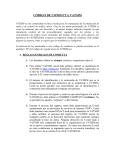
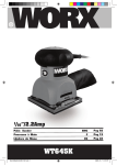
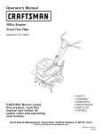
1
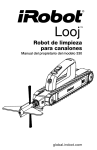
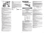
MANUAL DE USUARIO
GARANTÍA LIMITADA
1. DURACIÓN: A partir de la fecha de la compra del comprador original como lo siguiente: Wood Industries,
Inc. (Deber estándares y No anunciado- un año).
2. QUIEN DA ESTA GARANTÍA (GARANTIZADOR): Wood Industries, Inc. Domicilio: 21 Front Street,
Belmont, MS 38827, USA.
3. QUIEN RECIBE ESTA GARANTÍA (COMPRADOR): El comprador original (con excepción con objeto de
de reventa) del producto de Wood Industries, Inc.
4. QUÉ PRODUCTOS SON CUBIERTOS POR ESTA GARANTÍA: Cualquier Clavador de Wood Industries,
Inc., grapadora o accesorio de aire o proporcionado o fabricado por Garantizador.
5. QUÉ SE CUBRE BAJO ESTA GARANTÍA: Defectos substanciales en material y la ejecución que ocurren
dentro de la duración del período de la garantía.
6. QUÉ NO SE CUBRE BAJO ESTA GARANTÍA:
USERS MANUAL
2-1/2" 34 Angle Finish Nailer
A. Las garantías implicadas, incluyendo la comerciabilidad y de la APTITUD PARA UN PROPÓSITO PARTICULAR SON
LIMITADAS A PARTIR DE LA FECHA DE LA COMPRA ORIGINAL SEGÚN LO INDICADO EN LA DURACIÓN. Si
este producto se utiliza para los propósitos comerciales, industriales o de alquiler, la garantía aplicará noventa (90) días a
partir de la fecha de la compra. Algunos estados no permiten la limitación encendido cuánto tiempo una garantía
implicada dura, así que las limitaciones antedichas pueden no aplicarse a usted.
B. PÉRDIDA, DAÑOS, O COSTO FORTUITO, INDIRECTO, O CONSECUENTE QUE PUEDE RESULTAR DE
CUALQUIER DEFECTO, FALLA, O MALFUNCIÓN DE PRODUCTO DE WOOD INDUSTRIES, INC. Algunos
estados no permiten la exclusión o la limitación de daños fortuitos o consecuentes, así que la limitación o la exclusión
antedicha puede no aplicarse a usted.
C. Cualquier falta que resulte de un accidente, abuso del comprador, negligencia o de la falta de funcionar productos de
acuerdo con instrucciones proporcionados en el manual del dueño (s) proporcionado con el producto. El accidente,
abuso del comprador, negligencia o la falta de funcionar productos de acuerdo con instrucciones también incluirán el
retiro o la alteración de cualquier dispositivo de seguridad. Si se quitan o se alteran tales dispositivos de seguridad, esta
garantía es invalido.
D. Los ajustes normales que se explican en el manual del dueño (s) proporcionaron el producto.
E. Artículos o servicio que se requieren normalmente mantener el producto, es decir anillo o, resortes, topes, juntas, sellos,
inyectores, mangueras materiales, o cualquier otra parte consumible enumerada no específicamente. Estos artículos
serán cubiertos solamente por noventa (90) días a partir de la fecha de la compra original. Los artículos subrayados se
autorizan para los defectos en material y la ejecución solamente.
F. Defectos cosméticos que no interfieren con la función del producto.
7. RESPONSABILIDADES DEL GARANTIZADOR BAJO ESTA GARANTÍA: Repare o substituya, en la opción de
Garantizador, productos o componentes que son defectuosos, han funcionado incorrectamente y/o no han podido
conformarse dentro de la duración del período de la garantía.
8. RESPONSABILIDADES DEL COMPRADOR BAJO ESTA GARANTÍA:
A. Proporcione la prueba anticuada de los expedientes de la compra y del mantenimiento.
B. Llame 1 800 551 2406 para obtener sus opciones de servicio de la garantía. Los costes de la carga se deben llevar por
el comprador.
C. Utilice el cuidado razonable en la operación y el mantenimiento de los productos según lo descrito en el manual del
dueño (s).
9. CUANDO EL GARANTIZADOR REALIZARÁ LA REPARACIÓN O EL REEMPLAZO BAJO ESTA GARANTÍA: La
reparación o el reemplazo programar y será mantenida según el flujo normal del trabajo en la localización de
mantenimiento, y dependiendo de la disponibilidad de las piezas de recambio.
Esta garantía limitada se aplica en los Estados Unidos, Canadá y México solamente y le da los derechaos legales
espec ficos. Usted puede también tener otros derechos que varíen de estado al estado o de país a país.
TO PREVENT SERIOUS INJURY, READ AND UNDERSTAND ALL
WARNINGS AND INSTRUCTIONS BEFORE USE.
Wood Industries, Inc.
21 Front Street, Belmont, MS 38827
No portion of this manual or any artwork contained herein may be reproduced in any
shape of form without the express written consent of Wood Industries, Inc.
Copyright 2009 by Wood Industries, Inc.
Todos los derechos reservados.
Sp10
MODEL: IH-AFN34
Hecho en China
For technical questions and replacement parts, please call 1 800 551 2406
Copyright 2009 by Wood Industries, Inc. All rights reserved.
USERS MANUAL
CONTENTS:
IMPORTANT INFORMATION
EXPLANATION OF THE NAILING ACTION
GENERAL SAFETY RULES
WORK AREA
PERSONAL SAFETY
TOOL USE AND CARE
SERVICE
AIR SOURCE
DESCRIPTION AND SPECIFICATION
SPECIFICATION
FEATURES
ASSEMBLY/INSTALLATION
OPERATION
LUBRICATION
ADJUSTING AIR PRESSURE
CONNECTING AIR SUPPLY
TOOL TESTING
NAIL LOADING
METHODS OF OPERATION
COLD WEATHER OPERATION
ADJUSTING THE NAILING DEPTH
ADJUSTABLE THE EXHAUST
NO-MAR TIP
MAINTENANCE
JAM CLEARING
CLEANING
STORAGE
HOOKUP INSTRUCTIONS FOR TOOL TO AIR SUPPLY
RECOMMENDED HOOKUP
TROUBLE SOLVING
LIMITED WARRANTY
Manguera
de aire
P1
P1
P1
P1
P1
P1
P2
P2
P3
P3
P4
P4
P4
P4
P4
P4
P5
P6
P6
P7
P7
P7
P7
P7
P8
P8
P8
P8
P8
P9
P10
Conectador
EngrasadorFiltro
rápido
Acoplador
Regulador
rápido
compresor
SOLUCIONAR DE AVERÍA
PROBLEMAS
CAUSAS POSIBLES
SOLUCIONES SUGERIDAS
Fuga de aire cerca de la cima
de la herramienta o en el
área del disparador.
1. Suelte los tornillos.
2. Anillos o o sellos gastados o dañados.
1. Apriete los tornillos.
2. Instale el kit del reacondicionamiento.
Fuga de aire cerca del fondo
de la herramienta.
1. Suelte los tornillos.
2. O anillos o sellos gastados o dañados.
1. Apriete los tornillos.
2. Instale el kit del reacondicionamiento.
Herramienta no hace nada o
funciona lentamente.
1. Suministro de aire inadecuado.
2. La herramienta es demasiado seca.
3. Extractor bloqueado.
4. O anillos o sellos gastados o dañados.
1. Cerciórese de que el compresor de aire esté
fijado entre 70PSI y 110PSI.
2. Agregue cerca de 2 3 gotas de lubricación
en el conectador del aire.
3. Limpie el canal del extractor.
4. Instale el kit del reacondicionamiento.
Los sujetadores se atoran en 1. Se usa el canal del conductor.
la herramienta con frecuencia 2. El pistón es quebrado o gastado.
3. Sujetadores doblados.
4. Compartimiento sucio.
5. Compartimiento flojo.
6. Sujetadores incorrectos.
Sp9
1. Fije el canal de impulsión.
2. Substituya el pistón.
3. Quite los sujetadores doblados, substitú
yalos por los sujetadores derechos.
4. Limpie el compartimiento.
5. Apriete los tornillos.
6. Verifique que los sujetadores sean
el tamaño correcto.
IH-AFN34
MANUAL DE USUARIO
NOTE:
IMPORTANT INFORMATION
MANTENIMIENTO
TO AVOID SERIOUS PERSONAL INJURY, ALL USERS AND
EMPLOYERS/OWNERS MUST READ AND UNDERSTAND
ALL INSTRUCTIONS IN THIS MANUAL BEFORE OPERATING
OF MAINTAINING THIS TOOL.
Cuando es parada, la herramienta se debe desconectar y
almacenar en el caso del almacenaje en un lugar caliente y seco.
El casquillo de la nariz puede reducir la profundidad de
Cuando la herramienta no será funcionando por un período
clavar debido a su grueso.
extendido, aplique una capa fina del lubricante a las piezas de
Se requiere el reajuste de profundidad de clavar.
acero para evitar moho.
No almacene la herramienta en a podría resistir al ambiente.
QUITAR ATASCO
Quite un clavo atorado en la orden siguiente:
1. Desconecte la manguera de aire.
2. Quite todos los clavos
3. Tire y abra el liberador de atasco
4. Teniendo cuidado para no hacer la curva o para no dañar
la lámina del conductor, usando alicates o un
destornillador si procede al claro el sujetador atorado.
5. Cierre el lanzamiento de atasco.
6. Vuelva a conectar la herramienta al recurso del aire.
7. Recargue la herramienta con el sujetador.
INSTRUCCIONES DE CONEXIÓN
PARA LA HERRAMIENTA AL
SUMINISTRO DE AIRE
NOTA:
Para un funcionamiento mejor, instale un enchufe rápido de 3/8
pulgadas (1/4 pulgadas de hilos de rosca NPT) con un diámetro
interior de 0. 315 pulgadas (8mm) en el fabricante de clavos y
3/8 avanzan a poquitos el acoplador rápido en la manguera de
aire.
1. Con el interruptor ENCENDER/APAGAR en la posición de
APAGADO, compresor del enchufe en el enchufe eléctrico.
2. Cierre el regulador de presión dando vuelta hasta el final a la
FIG. 16
Liberar
atasco
3.
4.
5.
6.
LIMPIEZA
ADVERTENCIA
Al limpiar una herramienta tenga cuidado no al desmontaje
cualquier parte de la herramienta puesto que los componentes
internos pueden ser mal colocados o los componentes de
seguridad pueden ser montados incorrectamente. Ciertos
agentes de limpieza tales como gasolina, carbón tetraclorido,
amoníaco. etc. puede dañar partes plásticos y O anillos.
ADVERTENCIA
No procure limpiar insertando objetos acentuados con aberturas.
Los bordes agudos pueden dañar los componentes internos que
causan un peligro serio.
Las aberturas de la ventilación, el elemento del contacto del
trabajo, y el disparador deben ser mantenidos limpio y liberar de
materia extranjera. Limpie periódicamente la herramienta con de
aire comprimido.
Limpie el compartimiento quitan el metal o las virutas de madera
.
que pudieron haber acumulado en el compartimiento Limpie
periódicamente el compartimiento con aire comprimido.
ALMACENAJE
ADVERTENCIA
Mantenga fuera del alcance de los niños y del personal
desconocedores con la operación de la herramienta rabe el
almacén. Las herramientas son peligrosas en las manos del
personal desconocedor con la herramienta.
izquierda. Gire el compresor y déjelo bombear hasta el final
hasta la presión del cierre automático.
Una la manguera de aire al enchufe del regulador. Ajuste el
regulador de presión dando vuelta a la derecha de modo que
la presión del enchufe esté entre 70PSI a 110PSI.
Cargue los sujetadores la clavadora.
Apunte la clavadora en una dirección segura mientras que une
a la manguera de aire.
La clavadora es listo para usar. Usted puede necesitar ajustar
la presión del enchufe de alcanzar profundidad apropiada del
sujetador.
CONEXIÓN
RECOMENDADA
MINIMUMCOMPONENTS
REQUERIDO PARA LA CONEXIÓN
Compresor de aire: El compresor de aire debe poder
mantener un mínimo de 70PSI cuando están utilizando
la clavadora. Un suministro de aire inadecuado puede
causar una pérdida de energía y de conducir contrario.
Regulador de presión: Un regulador de presión se
requiere para controlar la presión de funcionamiento la
clavadora entre 70PSI y 110PSI.
Manguera del suministro de aire: Utilice siempre las
mangueras del suministro de aire con un clasificación
mínimo de la presión de funcionamiento igual a o mayor
que la presión de la fuente de energía, o 150PSI, cual
sea mayor. Utilice la manguera de aire de 1/4 pulgadas
para los funcionamientos hasta 50 pies. Uso manguera
de aire de 3/8 pulgadas para 50 pies, funcionamiento o
más de largo.
Utilice la manguera de aire de 1/4 pulgadas para los
funcionamientos hasta 50 pies. Uso manguera de aire
de 3/8 pulgadas para 50 pies, funcionamiento o más de
largo.
Sp8
The employer must enforce the use of safety glasses by
the tool operator and others in work area.
ALWAYS WEAR EAR AND HEAD PROTECTION. Always
wear ear protection to protect your ears from loud noise,
Always wear head protection to protect your head from
flying objects.
USE SAFETY EQUIPMENT. A dust mask, non skid safety
shoes and a hard hat must be used for the applicable
conditions. Wear a full face shield if you are producing
metal filings or wood chips.
DRESS PROPERLY. Do not wear loose clothing or
jewelry. Contain long hair. Keep your hair, clothing, and
gloves away from moving parts. Loose clothes, jewelry,
or long hair can be caught in moving parts and increases
the risk of injury.
STAY ALERT, WATCH WHAT YOU ARE DOING AND USE
COMMON SENSE WHEN OPERATING A POWER TOOL.
Do not use tool while tired or under the influence of
drugs, alcohol, or medication. A moment of inattention
while operating the tool may cause serious injury.
AVOID UNINTENTIONAL FIRING. Keep fingers away from
trigger when not driving fasteners, especially when
connecting the tool to the air supply.
DO NOT OVERREACH. keep proper footing and balance
at all times. Proper footing and balance enables better
control of the tool in unexpected situations.
MAKE SURE AIR HOSE IS FREE OF SNAGS AND
OBSTRUCTIONS. DO NOT ATTACH AN AIR HOSE OR
TOOL TO YOUR BODY. Entangled or snarled hoses can
cause a loss of balance or footing in addition to
unintentional tool operation. Attach the hose to the
structure to reduce the risk of loss of balance of the hose
shifts.
WARNING
keep this manual for the safety warnings and precautions,
operating, inspection, maintenance. Keep this manual and
the receipt in a safe and dry place for future reference.
EXPLANATION OF
THE NAILING ACTION
SINGLE ACTUATION MECHANISM:
First, press the safety against the wood; next, pull the
trigger to drive the fastener. After fastening once,
fastening will not be possible again until the trigger is
released and pressed again.
CONTACT ACTUATION MECHANISM:
First, press the safety against the wood; next, pull the
trigger to drive the fastener. First. Pull the trigger; next,
press the safety against the wood to drive the fastener. If
the trigger is held back, a fastener will be driven each
time the safety is pressed against the wood.
FULL SEQUENTIAL ACTUATION MECHANISM:
First, press the safety against the wood; next, pull the
trigger to drive the fastener. Follow the same sequence
to continue driving fasteners.
GENERAL SAFETY RULES
TOOL USE AND CARE
WORK AREA
NEVER POINT TOOL AT YOURSELF OR OTHERS IN
WORK AREA. Always assume the tool contains
fasteners. Never point the tool at yourself or others,
whether it contains fasteners or not. If fasteners are
mistakenly driven, it can lead to severe injuries. Never
engage in horseplay with the tool. Respect the tool as a
working implement.
KEEP FINGERS AWAY FROM TRIGGER WHEN NOT
DRIVING FASTENERS TO AVOID ACCIDENTAL FIRING.
Never carry the tool with finger on trigger since you
could drive a fastener unintentionally and injure yourself
or someone else. Always carry the tool by the handle
only.
NEVER MODIFY OR ALTER A TOOL. Doing so may cause
it to malfunction and personal injuries may result.
KNOW THIS TOOL. Read manual carefully, learn its
applications and limitations, as well as the specific
potential hazards related to this tool.
USE ONLY FASTENERS THAT ARE RECOMMENDED FOR
YOUR MODELS. Do not use the wrong fasteners or load
the fasteners incorrectly.
CHECK FOR MISALIGNMENT OR BINDING OF MOVING
PARTS, BREAKAGE OF PARTS, AND ANY OTHER
KEEP THE WORK AREA CLEAN AND WELL LIGHTED.
Cluttered benches and dark areas increase the risks of
accidents.
DO NOT OPERATE THE TOOL IN EXPLOSIVE
ATMOSPHERES, such as in the presence of flammable
liquids, gases, or dust. The tool creates a spark which
may ignite flammable liquids, gases or dust.
KEEP VISITORS AWAY. Do not let visitors handle the
tool. All visitors should be kept safety away from work
area.
NEVER ENGAGE IN HORSEPLAY WITH THE TOOL.
Respect the tool as a working implement.
PERSONAL SAFETY
OPERATORS AND OTHERS IN WORK AREA MUST WEAR
SAFETY GLASSES WITH SIDE SHIELDS. When operating
the tool, always wear safety glasses with side shields,
and make sure others in work area wear safety glasses,
tool. Safety glasses must conform to the requirements
of American National Standards Institute, ANSI Z87.1
and provide protection against flying particles both from
the front and side.
1
IH-AFN34
USERS MANUAL
TOOL SERVICE
CONDITION THAT MAY AFFECT THE TOOL'S OPERATION.
If damaged, have the tool serviced before using. Many
accidents are caused by poorly maintained tools.
CHECK SAFETY BEFORE USE. Make sure the safety
operates properly. Never use the tool unless the safety is
operating properly, otherwise the tool could drive a
fastener unexpectedly. Do not tamper with or remove
the safety, otherwise the safety becomes inoperable.
DO NOT USE TOOL IF TRIGGER DOES NOT ACTUATE
PROPERLY. Any tool that cannot be controlled with the
trigger is dangerous and must be repaired.
NEVER USE TOOL WHICH IS DEFECTIVE OR OPERATING
ABNORMALLY. If the tool appears to be operating
unusually, making strange noises, or otherwise appears
defective, stop using it immediately and arrange for
repairs by an authorized service center.
MAINTAIN TOOLS WITH CARE. Keep the tool clean and
lubricated for better and safer performance.
NEVER CARRY THE TOOL BY AIR HOSE.
STORE TOOLS OUT OF THE REACH OF CHILDREN AND
OTHER UNTRAINED PEOPLE. Tools are dangerous in the
hands of untrained users.
PLACE TOOL PROPERLY ON WORKPIECE. Do not drive
fasteners on top of other fasteners or with the tool at too
steep of an angle; the fasteners can ricochet and hurt
someone.
DO NOT USE THE TOOL AS A HAMMER.
KEEP ALL SCREWS AND COVERS TIGHTLY IN PLACE.
KEEP FACE, HANDS AND FEET AWAY FROM FIRING
HEAD AT ALL TIMES. Never place your face, hands or
feet near the firing head.
DO NOT DISCONNECT AIR HOSE FROM TOOL WITH
FINGER ON TRIGGER. The tool can fire when re
connected to an air supply.
DO NOT LOAD FASTENERS WITH TRIGGER PULLED OR
SAFETY DEPRESSED.
NEVER PLACE A HAND OR ANY PART OF BODY IN
FASTENER DISCHARGE AREA OF TOOL.
DO NOT DRIVE FASTENERS INTO THIN BOARDS OR
NEAR CORNERS AND EDGES OF WORKPIECE. The
fasteners can be driven or a way from the workpiece hit
someone.
DISCONNECT AIR HOSE FROM TOOL WHEN:
1). Doing maintenance and inspection;
2). Loading fasteners;
3). Turning the adjuster and top cover;
4). Attaching or removing the no mar tip;
5). Clearing a jam;
6). It is not in use;
7). Leaving work area;
8). Moving it to another location;
9). Handing it to another person.
Never attempt to clear a jam or repair the tool unless you
have disconnected air hose from the tool and removed
all remaining fasteners from the tool. The tool should
never be left unattended since people who are not
familiar with the tool might handle it and injure
themselves.
USE ONLY ACCESSORIES THAT ARE IDENTIFIED BY THE
MANUFACTURER FOR THE SPECIFIC TOOL MODEL
USE OF UNAUTHORIZED PARTS OR FAILURE TO FOLLOW
MAINTENANCE INSTRUCTIONS MAY CREATE A RISK OF
INJURY
USE ONLY THE LUBRICANTS SUPPLIED WITH THE TOOL
OR SPECIFIED BY THE MANUFACTURE.
TOOL SERVICE MUST BE PERFORMED ONLY BY
QUALIFIED REPAIR PERSONNEL.
AIR SOURCE
NEVER USE OXYGEN OR OTHER BOTTLED GASES AS A
POWER SOURCE. Explosion may occur. Combustible
gases and other bottled gases are dangerous and may
cause the tool to explode.
DO NOT EXCEED MAXIMUM RECOMMENDED AIR
PRESSURE MARKED ON THE TOOL. Use only clean, dry,
regulated, compressed air within the rated pressure
range marked on the tool. Never connect the tool to
pressure as which potentially exceeds 200PSI the tool
can burst.
DO NOT ABUSE THE AIR HOSE. Protect all hoses from
kinks, restrictions, solvents or sharp objects. Keep air
hose away from heat, oil, sharp edges or moving parts.
Replace damaged hoses immediately. Damaged hoses
can burst or whip around.
CHECK ALL FITTINGS, HOSES, PIPES, CONNECTIONS
AND COMPRESSOR BEFORE EACH USE OF THIS TOOL.
Repair or replace damaged or leaking hoses and
connections immediately. Damage to a hose or
connection can cause a pressure hose to break and whip
around the work area, and can lead to injury.
CONTACT FIRE
FIG.12
ADVERTENCIA
Para evitar la leña doble o la leña accidental debido al
retroceso.
No presione la herramienta contra la madera con la
fuerza excesiva.
SeparE la herramienta de la madera como ella retrocesa
después de clavar.
1). Jale el disparador con la herramienta del objeto
2). Presione la seguridad contra el objeto para conducir un
clavo
3). Mueva la herramienta a lo largo del objeto con un
movimiento que despide cada depresión de la seguridad
conducirán un clavo.
Tan pronto como el número deseado de clavos se haya
conducido quite el dedo del disparador
Muy profundo
Dé vuelta al contador de la perilla del ajuste a la derecha
FIG. 13
Demasiado bajo
Rubor
NOTA:
Siempre los maneje clavos y paquete cuidadosamente. Si
se caen los clavos, el enlace de compaginación puede estar
roto, que causará la falta de alimentación y atoración.
Después de clavar:
1). Desconecte la manguera de aire de la herramienta.
2). Quite todos los clavos de la herramienta.
3). Proporcione 5 10 gotas del lubricante neumático de la
herramienta en el enchufe del aire en la herramienta.
4). Abra la llave de purga en el tanque del compresor de aire
para drenar cualquier humedad.
Dé vuelta a la perilla del ajuste a la derecha
AJUSTE DEL EXTRACTOR
La dirección del respiradero del extractor puede ser cambiada
dando vuelta a la cubierta superior (FIG14).
FIG. 14
OPERACIÓN DE TIEMPO FRÍO
ADVERTENCIA
NO UTILICE UNA HERRAMIENTA EN ENFRIAMIENTO,permita que la
herramienta deshiele antes de usar. La humedad congelada en
la herramienta puede impedir componentes internos dando por
resultado el riesgo de lesión y/o daño de la herramienta.
Cuando usa la herramienta en condiciones fríos la herramienta
completará un ciclo más lentamente que generalmente
mientras que conduce los primeros clavos. La tasa del ciclo
aumentará como la herramienta calienta. Mantenga la
herramienta caliente para evitar tasa reducida del ciclo.
AJUSTAR LA PROFUNDIDAD DEL
CLAVO
USAR LA EXTREMIDAD NO ESTROPEA
ADVERTENCIA
Cuando la atadura o el separar extremidad no estropea,
sea seguro quitar su dedo del disparador y desconectar la
casa del aire del fabricante de clavos.
Si usted tiene gusto de proteger la superficie del objeto contra
los rasguños o las marcas hechos por la seguridad, una el
accesorio extremidad no estropea a la seguridad.
Para substituir extremidad no estropea:
ADVERTENCIA
Desconecte la herramienta de la fuente del aire antes de hacer
ajustes. Tales medidas de seguridad preventivas reducen el
riesgo o la operación inintencional de la herramienta.
1).Desconecte la manguera de aire de la herramienta.
2).Ponga extremidad no estropea al dedo del pie de la
seguridad.
Para quitar extremidad no estropea: Tire de la extremidad no
estropea no directamente lejos de la herramienta.
1. Desconecte la herramienta de suministro de aire.
2. Quite los clavos de la herramienta.Ajuste la herramienta de
conducir profundidad:
Para reducir la profundidad del clavo, dé vuelta al contador
3.
de la perilla del ajuste a la derecha (FIG.12).
Para conducir el clavo más profundo, dé vuelta a la perilla
del ajuste a la derecha (FIG. 13).
4. Recargue los clavos como descrito en la sección “ Cargas
clavos”de este manual.
5. Vuelva a conectar el suministro de aire.
2
Rubor
Sp7
FIG. 15
Seguridad
Extremidad
no estropea
IH-AFN34
MANUAL DE USUARIO
CARGAR CLAVO
FUNCTIONAL DESCRIPTION AND SPECIFICATIONS
ADVERTENCIA
ADVERTENCIA
Siempre cargue clavos en el compartimiento de la
herramienta antes de conectar el suministro de aire. Conectar
el suministro de aire después de que cargar clavos reduce el
riesgo inintencionalmente de conducir un clavo y de lesionarse a si
mismo o a otras personas.
ADVERTENCIA
Al cargar el compartimiento de herramientas, compruebe
que las extremidades del clavo entran en contacto con el
carril del desgaste y resbale suavemente contra la
superficie del compartimiento. Si los clavos no se cargan
correctamente, la herramienta fallará y los clavos se pueden
desviar, haciendo la herramienta reaccionar de una manera
inesperada, y dañan la herramienta.
1. Desconecte el suministro de aire.
2. Inserte la tira del clavo en la parte posterior del
compartimiento (FIG 7).
3. Resbale la tira del clavo adelante en el
compartimiento (FIG 8).
4. Tire del empujador del clavo de nuevo a contratan
el empujador a la tira del clavo (FIG 9).
MANTENGA LA HERRAMIENTA APUNTADA LEJOS DE SI MIS
MO Y DE OTROS AL CARGAR LOS SUJETADORES. LA FALTA
DE HACERLO PUEDE DAR LUGAR A DAÑOS CORPORALES
SERIOS POSIBLES.
SUJETADORES MÁS NUEVOS CARGADOS CON EL OBJETO
ENTRAN EN CONTACTO CON O DISPARADOR ACTIVADO. E
L HACERLO PUEDE DAR LUGAR A DAÑOS CORPORALES SE
RIOS POSIBLES.
WARNING
Disconnect the tool from the air source before making any adjustments, changing accessories or storing the tool. Such
precautionary safety measures reduce the risk or unintentional tool operation.
FIG. 1
Adjustable Exhaust
Deflector
QUITAR LOS CLAVOS:
1. Desconecte el suministro de aire.
2. Tire del empujador posterior (FIG. 10).
3. Vuelva el empujador adelante reservado mientras que
empuja el empujador.
4. Saque los clavos de la parte posteriora del compartimiento
(FIG. 11)
Air Cap
Hand Grip
FIG. 10
Trigger
Body
Air Plug
FIG. 7
Empujador
Clavador final
. 15Ga
FIG. 11
Depth of Driver
Adjustment
Magazine
Pusher
FIG. 8
Safety
No-Mar tip
MÉTODOS DE OPERACIÓN
Empujador
FIG. 9
Esta herramienta se equipa de la seguridad y no funciona a
menos que se presione la seguridad.
Hay dos métodos de operación para conducir clavos con
esta herramienta.
Son:
1. Fuego secuencial
2. Fuego de contacto
Fuego secuencial
1). Coloque el enchufe del clavo en el objeto con el dedo del
disparador.
2). Presione la seguridad firmemente hasta que se presiona
totalmente.
3). Jale del disparador para conducir un clavo.
4). Quite el dedo del disparador.
Para continuar clavando una localización separada, mueva la
herramienta a lo largo de la madera, repitiendo los pasos (2 5)
como sea necesario.
Sp6
Fastener Type
SPECIFICATIONS
Product Size:
Length 13.58"(345mm)
Height 12.76"(324mm)
Width 3.43"(87mm)
Weight: 4.62Ibs(2.1kg)
Normal Operating Pressure: 70 110PSI(0.5 0.75MPa)
Magazine Capacity: 100 Nails
Firing Mode: Sequential Fire/Contact Fire
Fastener Size Range:
15 Gauge Nails: 1 1/4" 2 1/2"(32 64mm)
0.11"
2.7(mm)
0.13"
3.2mm
0.071"- 0.073"
1.8- 1.84(mm)
34
32mm
38mm
45mm
50mm
57mm
64mm
3
1-1/4"
1-1/2"
1-3/4"
2"
2-1/4"
2-1/2"
IH-AFN34
USERS MANUAL
FEATURES
If the tool is not used with an in line lubrication system on
the air supply it is necessary to periodically lubricate the
tool with air tool lubrication.
Quick release latch for jams.
New designed light die cast alum alloy body.
Depth of penetration adjustable.
Exhaust direction adjustable and remain nails visible.
No Mar tip protects work surface.
Under low use, lubricate once a day. Under heavy use,
lubricate twice a day. To lubricate, insert 2 3 drops of
lubricant into the air supply fitting attached to the tool
handle (FIG 2). Using to much oil will cause it to collect in
the tool and be noticeable in the exhaust.
ASSEMBLY/INSTALLATION
FIG. 2
Follow the instructions below to prepare your tool for
operation.
2-3 Drops of
Air Tool Lubricant
Fije el botón a la posición ascendente totalmente
según las indicaciones del diagrama. Si no, no
funcionará correctamente.
ADVERTENCIA
No exceda la presión de aire recomendada máxima marcada
en la herramienta. Verifique antes de usar la herramienta que la
fuente del aire se ha ajustado dentro de la presión atmosférica
clasificada sonó. Sea seguro que la galga de presión de aire
está funcionando correctamente y que la comprueba por lo
menos dos veces al día. Las herramientas funcionadas superior
a su grado máximo de la presión pueden funcionar
anormalmente o estallar dando por resultado daños corporales.
Para conectar la herramienta con el compresor utilice
solamente las mangueras de aire neumáticas que resuelven los
criterios siguientes:
FIG. 5
Botón
Posición ascendente
1. MGrado mínimo de la presión de la manguera, 200PSI.
2. Diámetro interno de la manguera mínima, 1/4 pulg.
3. Longitud máxima de la manguera, 100 pies.
1. All tool operators and their immediate supervisors must
become familiar with the operator safety instructions
before operating the tool.
2. Included with each tool are one copy of these
Operating/Safety Instructions. Keep this publications for
future reference.
3. Install a filter, regulator, lubricator unit and moisture trap
on your air delivery system per the manufacturer's
instructions for these devices. Additionally, install a
pressure gauge as close as practical to the tool,
preferably within 10 feet.
4. Select hoses with a minimum inner diameter of 1/4
inches and a maximum length of 100 feet.
FIG. 4
CONTACTO CON MECANISMO DE IMPULSIÓN.)
Set the button to the downward position
Completely as shown in the diagram. Otherwise,
it will not operate properly.
Do not use detergent oil, WD 40, transmission fluid, motor
oil, or other lubricants not specifically designated as air tool
lubricants. These lubricants will cause accelerated wear to
the seals, o rings, and bumpers in the tool, resulting in
poor tool performance and frequent maintenance.
WARNING
ADJUSTING AIR PRESSURE
To reduce the risk of injury from a hose bursting, select
hoses that are rated at least 200PSI.
5. Select fittings that are appropriately sized for the
selected hoses. The tool and air hose must have a hose
coupling such that all pressure is removed from the tool
when the coupling joint is disconnected.
Adjust the air pressure at recommended operating
pressure 70 110PSI according to the length of nails and
the hardness of workpiece.
The correct air pressure is the lowest pressure which will
do the job. Using the tool at a higher than required air
pressure unnecessarily over stresses the tool. Don't exceed
110PSI.
WARNING
Never use non relieving couplers and/or female quick
disconnect couplings on the tool. Non relieving couplings
and female couplings will trap high pressure air in the tool
when the air line is disconnected. This will leave the tool
charged with enough air after it has been disconnected to
drive a nail. Only MALE pneumatic type air connectors
should be fitted to the tool, so that high pressure air in the
tool is vented to atmosphere as soon as the air line is
disconnected.
6. Set the regulator at the air delivery system to a PSI that
falls within the tool's operating range of 70 110PSI. The
correct pressure is the lowest pressure that will do the
job.
FIG. 3
70PSI Minimum
110PSI Maximum
CONNECTING AIR SUPPLY
WARNING
Never use oxygen or other bottled gases as a power source.
Explosion may occur. Combustible gases and other bottled
gases are dangerous and may cause the tool to explode.
OPERATION
WARNING
Never connect the tool to an air source that is capable of
producing air pressure exceeding 200PSI. Excessive
pressure can cause abnormal operation or cause the tool to
burst, resulting in personal injury.
LUBRICATION
WARNING
USE ONLY THE AIR TOOL LUBRICANTS SUPPLIED WITH
THE TOOL. Do not use other lubricants as they may
damage the tool.
FIG. 6
Botón
Conectar el suministro de aire:
Broche la manguera de aire sobre el conectador rápido.
Revise la fuga de aire. Si se observa la fuga, deje de usar la
herramienta inmediatamente y realizado por el personal
calificado de reparación.
Sea seguro que la galga de presión de aire está funcionando
correctamente y compruebe por lo menos dos veces al día.
Posición ascendente
PRUEBA DE LA HERRAMIENTA
PELIGRO
OPERADORES Y OTROS EN ÁREA DE TRABAJO DEBEN USAR
LENTES DE SEGURIDAD CON LOS PROTECTORES LATERALES QUE
CUMPLEN CON ESPECIFICACIONES ANSI Z87. 1.
ADVERTENCIA
NUNCA UTILICE LA HERRAMIENTA A MENOS QUE LA SEGURIDAD
ESTÉ FUNCIONANDO CORRECTAMENTE.
Antes de que realmente comience el trabajo de clavar, pruebe la
herramienta usando la lista de cheque abajo, conduzcan la
prueba en la orden siguiente.
Si ocurre la operación anormal, pare el usar de la herramienta y
realizado por el personal cualificado de la reparación
inmediatamente.
1. Desconecte la manguera de aire de la herramienta. Quite
todos los clavos de la herramienta.
TODOS LOS TORNILLOS DEBE SER APRETADOS. Si
algunos tornillos son flojos, apriételos.
LA SEGURIDAD Y EL DISPARADOR DEBE MOVERSE
SUAVEMENTE
2. Ajuste la presión de aire a 70PSI, conecte la manguera
de aire. No cargue ninguna clavos en la herramienta. Fije
la conmutación a la posición ascendente.
3.
LA HERRAMIENTA NO DEBE TENER FUGA DE AIRE.
Quite el dedo del disparador y presione la seguridad contra la
madera.
4. LA HERRAMIENTA NO DEBE FUNCIONAR
Separe la seguridad de la madera. Después, apunte la
herramienta hacia abajo, jale el disparador y después espere
en esa posición por 5 segundos o más largo.
5. LA HERRAMIENTA NO DEBE FUNCIONAR.
1).Sin tocar el disparador, presione la seguridad contra el
objeto. Jale el disparador.
LA HERRAMIENTA DEBE FUNCIONAR.
2).Sostenga a cabo el disparador detrás mientras que
separa la seguridad de la madera.
La herramienta permanecerá en estado funcionado (la
lámina del conductor permanecerá en el fondo).
3). Quite el dedo del disparador.
La operación de la herramienta terminará (la lámina del
conductor volverá a la tapa. )
6. Si no se observa ninguna operación anormal, usted puede
cargar clavos en la herramienta. Conduzca los clavos en el
objeto que es el mismo tipo que se utilizará en el uso real.
LA HERRAMIENTA DEBE FUNCIONAR CORRECTAMENTE.
MECANISMO DE IMPULSIÓN SOLA.
4
Sp5
IH-AFN34
MANUAL DE USUARIO
CARACTERÍSTICAS
Cierre liberar rápido para los atascos.
Dado ligero nuevo diseñado cuerpo aleación de
aluminio.
Profundidad de penetración ajustable.
Agote la dirección ajustable y siga siendo clavos visibles.
Extremidad sin estropear protege la superficie de trabajo.
ASAMBLEA/INSTALACIÓN
Siga las instrucciones abajo de preparar su
herramienta para la operación.
1. Todos los operadores de la herramienta y sus supervisores
inmediatos deben convertirse al corriente de las instrucciones
de seguridad del operador antes de funcionar la herramienta.
2. Se incluye con cada herramienta una copia de estas
Instrucciones de Operacion/Seguridad. Guarde este las
publicaciones para la referencia futura.
3. Instale un filtro, regulador, unidad del lubricador y un colector de
humedad en su sistema de la entrega de aire por las
instrucciones del fabricante para estos dispositivos. Además,
instale una galga de presión tan cerca como práctica a la
herramienta, preferiblemente a 10 pies.
4. Seleccione las mangueras con un diámetro interno mínimo
de 1/4 pulgadas y una longitud máxima de 100 pies.
ADVERTENCIA
Para reducir el riesgo de lesión de una manguera que
estalla, seleccione las mangueras que son por lo menos
5. Seleccione las guarniciones que se clasifican apropiadamente
para las mangueras seleccionadas, la herramienta y
manguera de aire debe tener una manguera el juntar de tales
que toda la presión está quitada de la herramienta cuando se
desconecta el empalme del acoplador.
ADVERTENCIA
Nunca utilice no relevar los acopladores y/o los acopladores de
desconexión rápida femeninos en la herramienta. No relevar
acopladores y acopladores de hembra atrapará el aire de alta
presión en la herramienta cuando se desconecta la línea de
aire. Esto saldrá de la herramienta cargada con bastante aire
después de que se haya desconectado para conducir un
clavo. Solamente el tipo neumático MASCULINO
conectadores del aire se debe caber a la herramienta, para
expresar el aire de alta presión en la herramienta a la
atmósfera tan pronto como se desconecte la línea de aire.
6. Fije el regulador en el sistema de la entrega de aire a una PSI
que baje dentro del rango de operación de la herramienta
de70 110PSI.La presión correcta es la presión más baja que
hará el trabajo.
UTILICE SOLAMENTE LOS LUBRICANTES DE LA HERRAMIENTA DEL
AIRE PROPORCIONADOS CON LA HERRAMIENTA. No utilice otros
lubricantes como pueden dañar la herramienta
Si la herramienta no se utiliza con un sistema lubricante en línea
en el suministro de aire es necesario lubricar periódicamente la
herramienta con la lubricación de la herramienta del aire.
Bajo uso bajo, lubrique una vez al día, bajo uso pesado, lubrican
dos veces al día, para lubricar, insertan 2 3 gotas del lubricante
en la guarnición del suministro de aire unida a la manija de la
herramienta (FIG2). El usar a mucho aceite lo hará recoger en
la herramienta y ser sensible en el extractor.
FIG. 2
ADVERTENCIA
FIG. 5
Button
Upward position
1. Minimum hose pressure rating, 200PSI.
2. Minimum hose inner diameter, 1/4 in.
3. Maximum hose length, 100 ft.
FIG. 4
CONTACT ACTUATION MECHANISM)
Set the button to the downward position Completely as
shown in the diagram. Otherwise, it will not operate
properly.
FIG. 6
Button
No utilice el aceite detergente, WD 40, líquido de la transmisión,
aceite del motor, u otros lubricantes señalados no específicamente
como lubricantes de la herramienta del aire, estos lubricantes
causarán desgaste acelerado a los sellos, a los anillos o, y a los
topes en la herramienta, dando por resultado funcionamiento
pobre de la herramienta y mantenimiento frecuente.
ADJUSTING AIR PRESSURE
Ajuste la presión de aire en la presión de funcionamiento
recomendada 70-110PSI según la longitud de clavos y la
dureza del objeto.
La presión de aire correcta es la presión más baja que hará el
trabajo. Usar la herramienta en un excedente más altamente
que requerido de la presión de aire tensiona innecesariamente
la herramienta. No exceda 110PSI.
FIG. 3
Mínimo 70 PSI
Máximo 110 PSI
CONECTAR A SUMINISTRO DE AIRE
ADVERTENCIA
Nunca utilice el oxígeno u otros gases en botella como una
explosión de la fuente de energía puede ocurrir.Los gases
combustibles y otros gases en botella son peligrosos y pueden
hacer la herramienta estallar.
OPERACIÓN
LUBRICACIÓN
2 3 Gotas del lubricante de
la herramienta del aire
Set the button to the upward position Completely as
shown in the diagram. Otherwise, it will not operate
properly.
WARNING
Do not exceed maximum recommended air pressure
marked on the tool. Verify prior to using the tool that the air
source has been adjusted within the rated air pressure
rang. Be sure the air pressure gauge is operating properly
and check it at least twice a day. Tools operated in excess
of their maximum pressure rating may operate abnormally
or burst resulting in personal injury.
To connect the tool to the compressor only use pneumatic
air hoses that meet the following criteria:
ADVERTENCIA
Nunca conecte la herramienta con una fuente del aire que
sea capaz de producir la presión de aire que excede
200PSI. La presión excesiva puede causar la operación
anormal o hacer la herramienta estallar, dando por resultado
daños corporales.
Sp4
Connect the air supply:
Snap the air hose onto the quick connector.
Check for air leakage. If leakage is noted, cease using the
tool immediately and performed by qualified repair
personnel.
Be sure the air pressure gauge is operating properly and
check it at least twice a day.
Downward position
TOOL TESTING
DANGER
THE TOOL MUST NOT LEAK AIR.
3. Remove the finger from the trigger and press the safety
against the wood.
THE TOOL MUST NOT OPERATE.
4. Separate the safety from the wood. Next, point the tool
downward, pull the trigger and then wait in that position
for 5 seconds or longer.
THE TOOL MUST NOT OPERATE.
5. 1). Without touching the trigger, depress the safety
against the workpiece. Pull the trigger.
THE TOOL MUST OPERATE
2). Hold the trigger back while separating the safety
from the wood.
The tool will remain in operated status(the driver blade
will remain at the bottom).
3). Remove the finger from the trigger.
Tool operation will end (the driver blade will return to the
top).
6. If no abnormal operation is observed, you may load
nails in the tool. Drive nails into the workpiece that is the
same type to be used in the actual application.
THE TOOL MUST OPERATE PROPERLY.
OPERATORS AND OTHERS IN WORK AREA MUST WEAR
SAFETY GLASSES WITH SIDE SHIELDS WHICH CONFORMS
TO ANSI Z87.1 SPECIFICATIONS.
WARNING
NEVER USE TOOL UNLESS SAFETY IS OPERATING
PROPERLY.
Before actually beginning the nailing work, test the tool by
using the check list below. Conduct the test in the following
order.
If abnormal operation occurs, stop using the tool and
performed by qualified repair personnel immediately.
1. Disconnect air hose from tool. remove all nails from
tool.
ALL SCREWS MUST BE TIGHTENED. If any screws are
loose, tighten them.
THE SAFETY AND TRIGGER MUST MOVE SMOOTHLY.
2. Adjust the air pressure to 70PSI, connect the air hose.
do not load any nails in the tool. Set the switching to the
upward position.
SINGLE ACTUATION MECHANISM.
5
IH-AFN34
USERS MANUAL
NAIL LOADING
DESCRIPCIÓN FUNCIONAL Y ESPECIFICACIONES
WARNING
WARNING
KEEP THE TOOL POINTED AWAY FROM YOURSELF AND
OTHERS WHEN LOADING FASTENERS. FAILURE TO DO SO
COULD RESULT IN POSSIBLE SERIOUS PERSONAL INJURY.
Always load nails into the tool's magazine before the air
supply is connected. Connecting the air supply after loading
nails reduces the risk of unintentionally driving a nail and
injuring yourself or someone else.
NEVER LOAD FASTENERS WITH THE WORKPIECE
CONTACT OR TRIGGER ACTIVATED. DOING SO COULD
RESULT IN POSSIBLE SERIOUS PERSONAL INJURY.
WARNING
When loading the tools magazine, check that the nail tips
contact the wear rail and slide smoothly against the surface
of the magazine. If the nails are not loaded properly, the
tool will misfire and nails can be deflected, causing the tool
to react in an unexpected manner, and damage the tool.
REMOVING THE NAILS:
1. Disconnect air supply.
2. Pull the pusher backward(FIG 10).
3. Return the pusher forward quietly while pushing the
pusher.
4. Pull out nails from the back of the magazine(FIG 11).
1 .Disconnect air supply.
2 .Insert nail strip into the back of the magazine (FIG 7).
3 .Slide the nail strip forward in the magazine (FIG 8).
4 .Pull the nail pusher back to engage the pusher to the nail
strip (FIG 9).
ADVERTENCIA
Desconecte la herramienta de la fuente del aire antes de hacer cualesquiera accesorios de los ajustes,
el cambiar o almacenar la herramienta. Tales medidas de seguridad preventivas reducen el riesgo o la
operación inintencional de la herramienta.
FIG. 1
Desviación ajustable
del extractor
Casquillo de aire
Apretón Disparador
de mano
FIG. 10
Enchufe de aire
Cuerpo
FIG. 7
Pusher
Finish Nailer
15Ga.
FIG. 11
Profundidad del ajuste
de la impulsión
Compartimiento
FIG. 8
Empujador
Seguridad
METHODS OF OPERATION
This tool is equipped with the safety and does not operate
unless the safety is depressed.
There are two methods of operation to drive nails with this
tool.
Pusher
They are:
1. Sequential fire
2. Contact fire
FIG. 9
SEQUENTIAL FIRE
1).Position the nail outlet on the workpiece with finger off
the trigger.
2).Depress the safety firmly until it is completely
depressed.
3).Pull the trigger to drive a nail.
4).Remove finger from the trigger.
6
Extremidad no estropea
ESPECIFICACIONES
Tamaño del producto:
Longitud 13.58"(345mm)
Altura 12.76"(324mm)
Anchura 3.43"(87mm)
Peso: 4.62Ibs(2.1kg)
Presión de funcionamiento normal: 70 110PSI(0.5
0.75MPa)
Capacidad del compartimiento:100 clavos
Modo de afinar: Fuego secuencial / Contacto de fuego
Gama del tamaño del sujetador:
15 galga de clavo 1 1/4" 2 1/2"(32 64mm)
Tipo del sujetador
0.11"
2.7(mm)
0.13"
3.2mm
0.071"- 0.073"
1.8- 1.84(mm)
34
32mm
38mm
45mm
50mm
57mm
64mm
Sp3
1-1/4"
1-1/2"
1-3/4"
2"
2-1/4"
2-1/2"
IH-AFN34
MANUAL DE USUARIO
CONDICIONE QUE PUEDEN AFECTAR LA OPERACIÓN DE LA
HERRAMIENTA. Si está dañado, tenga la herramienta
mantenida antes de usar. Muchos accidentes son causados
por las herramientas mal mantenidas.
COMPRUEBE LA SEGURIDAD ANTES DE USAR. Asegure el
funcionamiento seguro correctamente, nunca utilice la
herramienta a menos que la seguridad esté funcionando
correctamente, si no la herramienta podría conducir un
sujetador inesperado. No trate de forzar con ni quite la
seguridad, si no la seguridad llega a ser inoperable.
NO UTILICE LA HERRAMIENTA SI EL DISPARADOR NO SE ACTÚA
CORRECTAMENTE. Cualquier herramienta que no se pueda
controlar con el disparador es peligrosa y debe ser reparada.
NUNCA UTILICE LA HERRAMIENTA QUE ES DEFECTUOSA O EL
FUNCIONAMIENTO ES ANORMAL. Si la herramienta aparece
funcionar inusualmente, la fabricación de ruidos extraños, o
aparece defectuosa, para el usar de ella inmediatamente y
arregla de otra manera para las reparaciones por un centro
de servicio autorizado.
MANTENGA LAS HERRAMIENTAS CON CUIDADO. Mantenga la
herramienta limpia y lubricada para un funcionamiento mejor
y más seguro.
NUNCA LLEVE LA HERRAMIENTA POR LA MANGUERA DE AIRE.
ALMACENE LAS HERRAMIENTAS FUERA DEL ALCANCE DE LOS
NIÑOS Y DE LA OTRA GENTE INEXPERIMENTADA. Las
herramientas son peligrosas en las manos de usuarios
inexperimentados.
COLOQUE LA HERRAMIENTA CORRECTAMENTE EN EL OBJETO.
No conduzca los sujetadores encima de otros sujetadores o
con la herramienta en demasiado escarpado de un ángulo;
los sujetadores pueden rebotar y lastimar a alguien.
NO UTILICE LA HERRAMIENTA COMO MARTILLO.
MANTENGA TODOS LOS TORNILLOS Y CUBIERTAS FIRMEMENTE
EN LUGAR.
SIEMPRE MANTENGA LA CARA, MANOS Y LOS PIES LEJOS DE
LA CABEZA DISPARADORA, nunca coloque su cara, manos o
los pies cerca de la cabeza disparadora.
NO DESCONECTE LA MANGUERA DE AIRE DE LA HERRAMIENTA
CON EL DEDO EN EL DISPARADOR. La herramienta puede
encender cuando está vuelta a conectar a un suministro de
aire.
NO CARGUE LOS SUJETADORES CON EL DISPARADOR TIRADO
O LA SEGURIDAD PRESIONADA.
NUNCA PONGA UNA MANO O CUALQUIER PARTE DEL CUERPO
EN EL ÁREA DE LA DESCARGA DEL SUJETADOR DE LA
HERRAMIENTA.
DNO CONDUZCA LOS SUJETADORES EN TABLEROS FINOS O
LAS ESQUINAS CERCANAS Y LOS BORDES DEL OBJETO. Los
sujetadores pueden ser conducidos o una manera del objeto
golpeó a alguien.
DESCONECTE LA MANGUERA DE AIRE DE LA HERRAMIENTA
CUANDO:
1). Hacer mantenimiento e inspección;
2). Cargando sujetadores;
3). Dar vuelta al ajustador y a la cubierta superior;
4). Atar o quitar cualquier extremidad que estropea;
5). Quitar un atasco;
6). No en uso;
7). Dejar área de trabajo;
8). Moverlo a otra localización;
9). Darlo a otra persona.
Nunca procure e quitar un atasco o repare la herramienta a
menos que usted haya desconectado la manguera de aire
de la herramienta y haya quitado todos los sujetadores
restantes de la herramienta. La herramienta debe nunca ser
dejada desatendida puesto que la gente que no está al
corriente de la herramienta pudo manejarla y dañarse.
SERVICIO DE HERRAMIENTA
UTILICE SOLAMENTE ACCESSORLES QUE SEAN
IDENTIFICADOS POR EL FABRICANTE PARA EL
MODELO ESPECÍFICO DE LA HERRAMIENTA.
EL USO DE PIEZAS DESAUTORIZADAS O LA FALTA DE
SEGUIR INSTRUCCIONES DEL MANTENIMIENTO
PUEDE CREAR UN RIESGO DE LESIÓN
UTILICE SOLAMENTE LOS LUBRICANTES
PROVEÍDOS DE LA HERRAMIENTA O ESPECIFICADOS
POR LA FABRICACIÓN.
EL SERVICIO DE LA HERRAMIENTA SE DEBE
REALIZAR SOLAMENTE POR EL PERSONAL
CALIFICADO DE REPARACIÓN.
FUENTE DE AIRE
Sp2
NUNCA UTILICE EL OXÍGENO U OTROS GASES EN BOTELLA
COMO FUENTE DE ENERGÍA. La explosión puede ocurrir. Los
gases combustibles y otros gases en botella son peligrosos y
pueden hacer la herramienta estallar.
NO EXCEDA LA PRESIÓN DE AIRE RECOMENDADA MÁXIMA
MARCADA EN LA HERRAMIENTA. Utilice solamente aire
comprimido limpio, seco, regulado, dentro de la gama
clasificada de la presión marcada en la herramienta. Nunca
conecte la herramienta con la presión como que
potencialmente excede 200PSI la herramienta puede
estallar.
NO ABUSE DE LA MANGUERA DE AIRE. Proteja todas las
mangueras contra torceduras, restricciones, solventes u
objetos agudos. Guarde la manguera de aire lejos del calor,
aceite, de bordes agudos o de piezas móviles. Substituya las
mangueras dañadas inmediatamente. Las mangueras
dañadas pueden estallar o azotar alrededor.
COMPRUEBE TODAS LAS GUARNICIONES, MANGUERAS, PIPAS,
CONEXIONES Y COMPRESOR ANTES DE CADA USO DE ESTA
HERRAMIENTA. Repare o substituya inmediatamente
dañadas o que se escapan las mangueras y las conexiones.
Dañe a una manguera o la conexión puede hacer una
manguera de la presión romperse y azotar alrededor del
área de trabajo, y puede conducir a lesión.
To continue nailing a separate location, move the tool
along the wood, repeating steps (2 5) as required.
FIG.12
Flush
Too Deep
CONTACT FIRE
WARNING
To avoid double firing or accidental firing due to recoil.
Do not press the tool against the wood with excessive
force.
Separate the tool from the wood as it recoils after nailing.
Turn the adjustment knob counter clockwise
FIG. 13
1).Pull the trigger with the tool off the workpiece.
2).Depress the safety against the workpiece to drive a nail.
3).Move the tool along the workpiece with a bouncing
motion. Each depression of the safety will drive a nail.
As soon as the desired number of nails have been driven,
remove finger from the trigger.
Too Shallow
Flush
NOTE:
Always handle nails and package carefully. If nails are
dropped, collating bond may be broken, which will
cause mis feeding and jamming.
After nailing:
1).Disconnect air hose from the tool.
2).Remove all nails from the tool.
3).Supply 5 10 drops of pneumatic tool lubricant into
the air plug on the tool.
4).Open the petcock on the air compressor tank to drain
any moisture.
Turn the adjustment knob clockwise
ADJUSTING THE EXHAUST
The direction of the exhaust vent can be changed by
turning the top cover (FIG14).
FIG. 14
COLD WEATHER OPERATION
WARNING
DO NOT USE A FROZEN TOOL. Allow tool to thaw before
using. Moisture frozen in the tool may impede internal
components resulting in the risk of injury and/or tool
damage.
When using the tool in cold conditions the tool will cycle
slower than usual while driving the first nails. The cycle rate
will increase as the tool warms up. Keep tool warm to avoid
reduced cycle rate.
USING THE NO-MAR TIP
WARNING
When attaching or detaching the No Mar Tip, be sure to
remove your finger from the trigger and disconnect the air
house from the nailer.
If you like to protect the surface of workpiece against
scratches or markings made by the safety, attach the
accessory No Mar Tip to the safety.
To replace the No Mar Tip:
1). Disconnect air hose from tool.
2). Put the No Mar Tip to the toe of the safety.
ADJUSTING THE NAILING DEPTH
WARNING
Disconnect the tool from the air source before making
adjustments. Such precautionary safety measures reduce
the risk or unintentional tool operation.
To remove the No Mar Tip: Pull the no mar tip directly
away from tool.
1. Disconnect tool from air supply.
2. Remove nails from the tool.
3. Adjust tool driving depth:
To reduce the nail depth , turn the adjustment knob
counter clockwise (FIG 12).
To drive the nail deeper, turn the adjustment knob
clockwise (FIG 13).
4. Reload nails as described in the "Loading Nails" section
of this manual.
5. Reconnect air supply.
FIG. 15
Safety
No-Mar Tip
7
IH-AFN34
USERS MANUAL
NOTE:
When not in use, the tool should be disconnected and
stored in the storage case in a warm and dry place. When
The nose cap may reduce nailing depth due to its thickness.
Re adjustment of nailing depth is required.
tool will not be in use for an extended period, apply a thin
coat of the lubricant to the steel parts to avoid rust.
Do not store the tool in a could weather environment.
MAINTENANCE
JAM CLEARING
HOOKUP INSTRUCTIONS FOR
TOOL TO AIR SUPPLY
Remove a jammed nail in the following order:
1. Disconnect air hose.
2. Remove all nails.
3. Pull and open the jam release.
4. Using caution not to bed or damage the driver blade,
using pliers or screwdriver if required to clear the
jammed fastener.
5. Close the jam release .
6. Reconnect the tool to the air resource.
7. Reload the tool with fasteners.
NOTE:
For better performance, install a 3/8 inch quick plug(1/4
inch NPT threads) with an inside diameter of 0.315 inch
(8mm) on the nailer and a 3/8 inch quick coupler on the air
hose.
1. With ON/OFF switch in OFF position, plug compressor
into electrical outlet.
2. Close pressure regulator by turning all the way to the
left. Turn compressor ON and let it pump all the way up
to automatic shut off pressure.
3. Attach air hose to regulator outlet. Adjust pressure
regulator by turning to the right so that outlet pressure is
between 70PSI to 110PSI.
4. Load fasteners into nailer.
5. Point the nailer in a safe direction while attaching to air
hose.
6. Nailer is ready for use. You may need to adjust outlet
pressure to achieve proper fastener depth.
FIG. 16
Jam
release
INFORMACIÓN IMPORTANTE
El patrón debe hacer cumplir el uso de las gafas de seguridad
del operador de la herramienta y de otras en área de trabajo.
ROTECCIÓN SIEMPRE DEL DESGASTE DEL OÍDO Y CABEZA.
Use siempre la protección auditiva para proteger sus oídos
contra ruido fuerte ;siempre use protector de cabeza contra
objetos voladores.
UTILICE EL EQUIPO DE SEGURIDAD. Una máscara de polvo,
zapatos antideslizantes de seguridad y un sombrero duro se
deben utilizar para las condiciones aplicables. Use un
protector lleno de la cara si usted está produciendo limaduras
de metal o virutas de madera.
VISTASE APROPIADAMENTE. No use la ropa o joyería floja.
Contenga el pelo largo. Guarde su pelo, ropa y guantes lejos
de piezas móviles. Las ropas flojas, joyería, o el pelo largo se
pueden coger en piezas móviles y aumentan el riesgo de
lesión.
ESTE ALERTE, MIRE QUÉ ESTÁ HACIENDO USTED Y USE EL
SENTIDO COMÚN AL FUNCIONAR UNA HERRAMIENTA
ELÉCTRICA. No utilice la herramienta mientras que es
cansado o bajo influencia de medicina, alcohol, o
medicación. Un momento de la inatención mientras que el
funcionamiento de la herramienta puede causar lesión seria.
EVITE DISPARO ININTENCIONAL.Guarde los dedos lejos del
disparador al no conducir los sujetadores, especialmente al
conectar la herramienta con el suministro de aire.
NO EXTRALIMITARSE.Mantenga el pie y el equilibrio siempre
apropiado. El pie y el equilibrio apropiado permite un control
mejor de herramienta en situaciones inesperadas.
CERCIÓRESE DE QUE LA MANGUERA DE AIRE ESTÉ LIBRE DE
GANCHOS Y DE OBSTRUCCIONES. NO ATE UNA MANGUERA O
UNA HERRAMIENTA DE AIRE A SU CUERPO. Las mangueras
enredadas o grunidas pueden causar una pérdida de
balance o de pie además de la operación inintencional de la
herramienta. Una la manguera a la estructura para reducir el
riesgo de la pérdida de balance de las cambios de la
manguera.
ADVERTENCIA
PARA EVITAR DAÑOS CORPORALES SERIOS, TODOS LOS
USUARIOS Y PATRONESDUEÑOS DEBEN LEER Y ENTENDER TODAS
LAS INSTRUCCIONES EN ESTE MANUAL ANTES DE FUNCIONAR O
MANTENIMIENTO DE ESTA HERRAMIENTA.
Guarde este manual para las advertencias y las precauciones
de seguridad, funcionamiento, inspección, mantenimiento.
Mantenga este manual y el recibo un lugar seguro y seco para
la referencia futura.
EXPLICACIÓN DE
ACCIÓN CLAVAR
MECANISMO DE SOLO IMPULSIÓN:
Primero, presione la seguridad contra la madera; después,
jale del disparador para conducir el sujetador, después de
sujetar una vez, sujetar no será posible otra vez hasta que el
disparador se suelte y se presione otra vez.
CONTACTO DE LMECANISMO DE IMPULSIÓN:
ridad contra la madera para conducir el sujetador. Si el
disparador se mantiene detrás, un sujetador será conducido
cada vez que la seguridad se presiona contra la madera.
Primero, presione la seguridad contra la madera; después,
jale del disparador para conducir el sujetador. Primero. Tire
del disparador, siguiente, presione la segu
MECANISMO DE IMPULSIÓN SECUENCIAL COMPLETO:
RECOMMENDED
HOOKUP
CLEANING
WARNING
MINIMUM COMPONENTS
REQUIRED FOR HOOKUP
When cleaning a tool be careful not to disassembly any
portion of the tool since internal components may be
misplaced or safety components may be improperly
mounted. Certain cleaning agents such as gasoline, carbon
tetrachloride, ammonia. etc. may damage plastic parts and
o rings.
Air compressor: The air compressor must be able to
maintain a minimum of 70PSI when the nailer is being
used. An inadequate air supply can cause a loss of power
and inconsistent driving.
Pressure regulator: A pressure regulator is required to
control the operating pressure of the nailer between 70PSI
and 110PSI .
Air supply hose: Always use air supply hoses with a
Minimum working pressure rating equal to or greater than
the pressure from the power source, or 150PSI, whichever
is greater. Use 1/4 inch air hose for runs up to 50 feet. Use
3/8 inch air hose for 50 feet, run or longer.
WARNING
Do not attempt to clean by inserting pointed objects through
openings. Sharp edges may damage internal components
causing a serious hazard.
Ventilation openings, the work contact element, and the
trigger must be kept clean and free of foreign matter.
Periodically clean the tool with compressed air.
Clean the magazine. Remove metal or wooden chips which
may have accumulated in the magazine. Periodically clean
magazine with compressed air.
Primero, presione la seguridad contra la madera; después,
jale del disparador para conducir el sujetador. Siga la misma
secuencia para continuar conduciendo los sujetadores.
REGLAS GENERALES DE
SEGURIDAD
USO Y CUIDADO DE LA HERRAMIENTA
ÁREA DE TRABAJO
MANTENGA EL ÁREA DE TRABAJO LIMPIA Y BIEN ILUMINADO.
Los bancos estorbados y las áreas oscuras aumentan los
riesgos de accidentes. accidents.
NO FUNCIONE LA HERRAMIENTA EN ATMÓSFERAS
EXPLOSIVAS, por ejemplo en presencia de líquidos
inflamables, gases, o el polvo, la herramienta crea una
chispa que pueda encender líquidos inflamables, gases o
polvo.
MANTENER VISITANTES AUSENTES. No deje a visitantes
manejar la herramienta. Todos los visitantes deben ser
mentenidos lejos del área de trabajo.
NUNCA HAGA JUEGOS CON LA HERRAMIENTA. Respete la
herramienta como instrumento de trabajo.
SEGURIDAD PERSONAL
LOS OPERADORES Y OTROS EN ÁREA DE TRABAJO DEBEN
USAR LAS GAFAS DE SEGURIDAD CON LOS PROTECTORES
LATERALES. Al funcionar la herramienta, use siempre las
gafas de seguridad con los protectores laterales, y cerciórese
de otros en gafas de seguridad del desgaste del área de
trabajo, filetean. Las gafas de seguridad deben cumplir con
los requisitos de American National Standards Institute, ANSI
Z87. 1 y proporciona la protección contra partículas
voladores contra el frente y el lado.
STORAGE
WARNING
Keep out of reach of children and personnel unfamiliar with
tool operation. Lock the storage area. Tools are dangerous
in the hands of personnel unfamiliar with the tool.
8
Sp1
NUNCA SEÑALE LA HERRAMIENTA A SI MISMO U OTROS EN EL
ÁREA DE TRABAJO.
Asuma siempre que la herramienta contiene los sujetadores.
Nunca señale la herramienta a si mismo u otros, si contiene
los sujetadores o no. Si los sujetadores se conducen
equivocadamente, puede conducir a lesiones severas.
Nunca haga juegos con la herramienta. Respete la
herramienta como instrumento de trabajo.
GUARDE LOS DEDOS LEJOS DEL DISPARADOS AL NO
CONDUCIR LOS SUJETADORES PARA EVITAR EL DISPARO
ACCIDENTAL.
Nunca lleve la herramienta con el dedo en disparador puesto
que usted podría conducir un sujetador inintencionalmente y
dañarse o a algún otro. Lleve siempre, la herramienta por la
manija solamente.
NUNCA MODIFIQUE O ALTERE UNA HERRAMIENTA..
El hacerlo puede hacerlo funcionar incorrectamente y los
daños corporales pueden resultar.
CONOSCA ESTA HERRAMIENTA.
Lea el manual cuidadosamente, aprenda sus usos y
limitaciones, así como los peligros potenciales específicos
relacionados con esta herramienta
UTILICE SOLAMENTE LOS SUJETADORES QUE SE
RECOMIENDAN PARA SUS MODELOS.
No utilice los sujetadores incorrectos ni cargue los
sujetadores incorrectamente.
COMPRUEBE PARA SABER SI HAY DESALINEAMIENTO O
ATASCAMIENTO DE PIEZAS MÓVILES, FRACTURA DE PIEZAS, Y
DE CUALQUIER OTRA.
IH-AFN34
MANUAL DE USUARIO
CONTENTS:
INFORMACIÓN IMPORTANTE
EXPLICACIÓN DE ACCIÓN CLAVAR
REGLAS GENERALES DE SEGURIDAD
ÁREA DE TRABAJO
SEGURIDAD PERSONAL
USO Y CUIDADO DE LA HERRAMIENTA
SERVICIO
FUENTE DE AIRE
DESCRIPCIÓN Y ESPECIFICACIONE
ESPECIFICACIONE
CARACTERÍSTICAS
ASAMBLEA/INSTALACIÓN
OPERACIÓN
LUBRICACIÓN
AJUSTE DE LA PRESIÓN DE AIRE
CONECTAR EL SUMINISTRO DE AIRE
PRUEBA DE LA HERRAMIENTA
CARGAR CLAVO
MÉTODOS DE OPERACIÓN
OPERACIÓN DE TIEMPO FRÍO
AJUSTAR LA PROFUNDIDAD DEL CLAVO
AJUSTE DEL EXTRACTOR
INDICADOR DEL CLAVO
EXTREMIDAA NO ESTROPER
MANTENIMIENTO
QUITAR ATASCO
LIMPIEZA
ALMACENAJE
INSTRUCCIONES DE CONEXIÓN PARA LA HERRAMIENTA AL SUMINISTRO DE AIRE
CONEXIÓN RECOMENDADA
SOLUCIONAR DE AVERÍA
P1
P1
P1
P1
P1
P1
P2
P2
P3
P3
P4
P4
P4
P4
P4
P4
P5
P5
P6
P6
P6
P6
P6
P7
P7
P7
TROUBLE SOLVING
PROBLEMS
POSSIBLE CAUSES
SUGGESTED SOLUTIONS
Air leaking near the top of
the tool or in the trigger
area.
1. Loose screws.
2. Worn or damaged O rings or seals.
1. Tighten screws.
2. Install overhaul kit.
Air leaking near the bottom
of the tool.
1. Loose screws.
2. Worn or damaged O rings or seals.
1. Tighten screws.
2. Install overhaul kit.
Tool dose nothing or
operates sluggishly.
1. Inadequate air supply.
2. Tool is too dry.
3. Exhaust blocked.
4. Worn or damaged O rings or seals.
1. Make sure the air compressor is set
between 70PSI and 110PSI.
2. Add about 2 3 drops of lubrication into
the air connector.
3. Clean exhaust channel.
4. Install overhaul kit.
Fasteners are jammed in
the tool frequently.
1. Driver channel is worn.
2. Piston is broken or worn.
3. Bent fasteners.
4. Dirty magazine.
5. Loose magazine.
6. Wrong fasteners.
1. Fix the drive channel.
2. Replace the piston.
3. Remove the bent fasteners, replace with
the right fasteners.
4. Clean magazine.
5. Tighten screws.
6. Verify that fasteners are the correct size.
P7
P7
P8
P9
9
USERS MANUAL
LIMITED WARRANTY
1. DURATION: From the date of purchase by the original purchaser as follows: Wood Industries, Inc(Standard Duty
and Unannounced -One Year).
2. WHO GIVES THIS WARRANTY (WARRANTOR): Wood Industries, Inc. Address: 21 Front Street, Belmont, MS
38827, USA.
3. WHO RECEIVES THIS WARRANTY (PURCHASER): The original purchaser (other than for purposes of resale) of
the Wood Industries, Inc. product.
4. WHAT PRODUCTS ARE COVERED BY THIS WARRANTY: Any Wood Industries, Inc. nailer, stapler or air
accessory supplied or manufactured by Warrantor.
5. WHAT IS COVERED UNDER THIS WARRANTY: Substantial defects in material and workmanship which occur
within the duration of the warranty period.
6. WHAT IS NOT COVERED UNDER THIS WARRANTY:
A.Implied warranties, including those of merchantability and FITNESS FOR A PARTICULAR PURPOSE ARE
LIMITED FROM THE DATE OF ORIGINAL PURCHASE AS STATED IN THE DURATION. If this product is used for
commercial, industrial or rental purposes, the warranty will apply for ninety (90) days from the date of purchase.
Some States do not allow limitation on how long an implied warranty lasts, so the above limitations may not
apply to you.
B.ANY INCIDENTAL, INDIRECT, OR CONSEQUENTIAL LOSS, DAMAGE, OR EXPENSE THAT MAY RESULT
FROM ANY DEFECT, FAILURE, OR MALFUNCTION OF WOOD INDUSTRIES, INC. PRODUCT. Some States do
not allow the exclusion or limitation of incidental or consequential damages, so the above limitation or exclusion
may not apply to you.
C.Any failure that results from an accident, purchaser's abuse, neglect or failure to operate products in accordance
with instructions provided in the owner's manual(s) supplied with product. Accident, purchaser's abuse, neglect
or failure to operate products in accordance with instructions shall also include the removal or alteration of any
safety devices. If such safety devices are removed or altered, this warranty is void.
D.Normal adjustments which are explained in the owner's manual(s) provided with the product.
E.Items or service that are normally required to maintain the product, i.e. o-ring, springs, bumpers, driver blades,
gaskets, seals, nozzles, material hoses, or any other expendable part not specifically listed. These items will only
be covered for ninety (90) days from date of original purchase. Underlined items are warranted for defects in
material and workmanship only.
F. Cosmetic defects that do not interfere with the product's function.
7. RESPONSIBILITIES OF WARRANTOR UNDER THIS WARRANTY: Repair or replace, at Warrantor's option,
products or components which are defective, have malfunctioned and/or failed to conform within duration of the
warranty period.
8. RESPONSIBILITIES OF PURCHASER UNDER THIS WARRANTY:
A. Provide dated proof of purchase and maintenance records.
B. Call 1-800-551-2406 to obtain your warranty service options. Freight costs must be borne by the purchaser.
C. Use reasonable care in the operation and maintenance of the products as described in the owner's manual(s).
9. WHEN WARRANTOR WILL PERFORM REPAIR OR REPLACEMENT UNDER THIS WARRANTY: Repair or
replacement will be scheduled and serviced according to the normal work flow at the servicing location, and
depending on the availability of replacement parts.
This Limited Warranty applies in the United States, Canada and Mexico only and gives you specific legal rights. You
may also have other rights which vary from state to state or country to country.
2-1/2''34 Clavadora de final
del ángulo
MODELO: IH-AFN34
PARA PREVENIR LESIÓN SERIA, LEA Y ENTIENDA TODAS LAS
ADVERTENCIASE INSTRUCCIONES ANTES DE USAR.
Wood Industries, Inc.
21 Front Street, Belmont, MS 38827
Copyright 2009 by Wood Industries, Inc. All rights reserved.
10
MANUAL DE USUARIO
Made in China
Ninguna parte de este manual o de cualquier ilustración contenida adjunto se puede
reproducir en cualquier manera de la forma sin el consentimiento expreso escrito de
Wood Industries, Inc.
Para las partes, información de producto y servicio visite www.eaglecompressor. COM
Para las preguntas técnicas y partes de recambio, por favor llame 1-800-551-2406
Copyright 2009 por Wood Industries, Inc. todos los derechos reservados.