Download Manual de instrucciones bilingüe (Español e Inglés)
Transcript
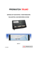
EQUIPOS DEIDE
DEIDE EQUIPMENT
SISTEMA DE DETECCIÓN, IDENTIFICACIÓN Y
MONITORIZACIÓN CONTINUA DE SEÑALES
RADIOELÉCTRICAS DE RADIO Y TV DIGITAL CON
CONTROL REMOTO
DETECTION, IDENTIFICATION AND CONTINUOUS
MONITORING SYSTEM FOR RADIO AND DIGITAL TV
SIGNALS WITH REMOTE CONTROL
- 0 MI1521 -
NOTAS SOBRE SEGURIDAD
Antes de manipular el equipo leer el manual de instrucciones y muy
especialmente el apartado PRESCRIPCIONES DE SEGURIDAD.
sobre el equipo significa "CONSULTAR EL MANUAL DE
El símbolo
INSTRUCCIONES". En este manual puede aparecer también como símbolo de
advertencia o precaución.
Recuadros de ADVERTENCIAS Y PRECAUCIONES pueden aparecer a lo largo de
este manual para evitar riesgos de accidentes a personas o daños al equipo u
otras propiedades.
SAFETY NOTES
Read the user’s manual before using the equipment, mainly " SAFETY RULES "
paragraph.
The symbol
on the equipment means "SEE USER’S MANUAL". In this
manual may also appear as a Caution or Warning symbol.
Warning and Caution statements may appear in this manual to avoid injury
hazard or damage to this product or other property.
SUMARIO
CONTENTS
English
Manual español................................................................................
English manual ................................................................................
MANUAL INSTRUCCIONES. EQUIPOS DEIDE
ÍNDICE
1. INTRODUCCIÓN....................................................................................................... 1
1.1
Funciones principales de los equipos DEIDE.................................................... 1
1.2
Descripción general del equipo ......................................................................... 4
1.3
Función básica de la aplicación DEIDE............................................................. 5
1.4
Software adicional ........................................................................................... 11
2. ESPECIFICACIONES.............................................................................................. 13
2.1
Sistema de equipos DEIDE: Unidad de Medida y Unidad de Control Remoto 13
2.1.1 Unidad de Medida (UM).............................................................................. 14
2.1.2 Receptor GPS............................................................................................. 14
2.1.3 Accesorios (opcionales).............................................................................. 15
2.2
Unidad de Control Remoto (UCR) ................................................................... 15
3. ESPECIFICACIONES DE LOS ACCESORIOS Y DOCUMENTACIÓN INCLUIDA 17
4. ESPECIFICACIONES DE ALIMENTACIÓN ELÉCTRICA DE LA ESTACIÓN............. 17
5. INSTRUCCIONES PARA EL MONTAJE DE LAS CONEXIONES Y PUESTA EN
MARCHA DEL EQUIPO .......................................................................................... 19
MANUAL INSTRUCCIONES. EQUIPOS DEIDE
MANUAL INSTRUCCIONES. EQUIPOS DEIDE
EQUIPOS DEIDE
SISTEMA DE DETECCIÓN, IDENTIFICACIÓN Y MONITORIZACIÓN
CONTINUA DE SEÑALES RADIOELÉCTRICAS DE RADIO Y TV DIGITAL
CON CONTROL REMOTO
1. INTRODUCCIÓN
1.1 Funciones principales de los equipos DEIDE
•
Detección de las señales radioeléctricas recibidas en una localización
determinada, en las bandas de radio y televisión analógica y digital.
•
Identificación de cada una de las señales recibidas obteniendo la información
que aporta el radiodifusor presente en la propia señal o bien por identificación
visual y/o sonora.
•
Monitorización permanente, automática y periódica de una zona variable del
espectro radioeléctrico, realizando un análisis de las variaciones detectadas.
•
El equipo o estación de medida puede realizar las operaciones anteriores en
modo local o bajo control de la Unidad de Control Remoto (UCR).
•
Trabaja con señales de radio digital (DAB), televisión digital terrestre (TDT)
según el estándar DVB-T (modulación en COFDM), radio FM-RDS y TV
analógica.
La unidad de medida está constituida por un PROLINK-4C Premium dotado de
las más avanzadas prestaciones, y por un procesador conectado en red mediante
protocolos SNMP y FTPS a través de una red privada virtual (VPN). A esta estación, la
denominamos Unidad de Medida (UM).
En el otro extremo de la conexión se halla la Unidad de Control Remoto (UCR).
Ésta estación está constituida por un ordenador, debidamente registrado y una
aplicación que permite gestionar de forma centralizada las diferentes Estaciones o
Unidades de Medida. El enlace de datos utiliza los siguientes protocolos de
comunicación: SNMP y FTPS para gestionar las Unidades de Medida (UM), HTTPS
para la comunicación mediante la aplicación DEIDE entre el cliente con un navegador y
la UCR, TCP o UDP para el envio de audio y video (video streaming) además soporta
el servicio de correos electrónicos mediante el protocolo SMTP, sincronización del reloj
de las UMs con el de la UCR y ofrece también como soporte online un escritorio remoto
para consultas técnicas.
Las UM pueden funcionar de forma autónoma a través de una UCR externa. En
caso de que el equipo no esté conectado a red puede controlarse a través de esta
UCR. Para ello, la UM debe estar registrada en su UCR interna con la IP 127.0.0.1 y no
tener conectado cable de red. Para más información ver el manual de la aplicación.
10/2007
Página 1
MANUAL INSTRUCCIONES. EQUIPOS DEIDE
UM 1
web
(H T
TP)
SN M
T PS
P/ F
P(*
/ NT
)
UM 2
SNMP / FTPS / NTP(*)
web (HTTP)
UM 3
we
b
CLIENTE
SERVIDOR
UCR
(H
TT
P)
web (HTTP)
SNMP / FTPS / NTP(*)
SN
MP
/F
TP
S
/N
TP
(*)
UM n
Figura 1.- Sistema DEIDE: Elementos y dispositivos.
(*) Protocolo NTP opcional
La Unidad de Control Remoto incluye funciones específicamente desarrolladas a
medida del usuario final. Basada en esta configuración, la UCR puede realizar
numerosas acciones:
•
Obtener información sobre el estado de la Unidad de Medida.
•
Programar procesos de medida en el tiempo, únicos o periódicos.
•
Adquirir información sobre los procesos de medida en curso y sobre procesos
de medida anteriores o acumulaciones estadísticas de los mismos (históricos).
•
Realizar medidas directas en tiempo real.
•
Controlar los procesos de medida (cambiar parámetros de funcionamiento).
•
Página 2
Presentar resultados de los datos, obtenidos (alarmas, históricos, estado del
sistema...).
10/2007
MANUAL INSTRUCCIONES. EQUIPOS DEIDE
•
•
Gestión remota y automática de versiones: Transferir nuevas versiones de las
aplicaciones de la Unidad de Medida (Updates).
Realizar procesos de vídeo y audio “streaming” para las señales de TV y radio
sintonizados.
•
Generar alarmas vía e-mail.
•
Control de acceso a la UCR y a las UM.
•
Gestión de prioridades de las UM y creación de grupos de usuario.
•
Supervisar el estado activo de las aplicaciones mediante un módulo de
protección (Watchdog).
Cada Unidad de Medida (UM) es un conjunto compacto y portátil de detección e
identificación, contenida totalmente en un armario rack estándar 3U de 19 pulgadas
especialmente diseñado para su protección y funcionamiento. Integra todos los
elementos necesarios para la operación continua de la unidad.
Figura 2.- Consola de la Unidad de Medida del equipo DEIDE (opcional).
10/2007
Página 3
MANUAL INSTRUCCIONES. EQUIPOS DEIDE
1.2 Descripción general del equipo
El sistema consta de los siguientes elementos:
•
Una Unidad de Control Remoto (UCR) para procesar los datos y controlar
todos los elementos del conjunto y así como la conexión de los distintos
usuarios (clientes) al servidor desde donde se ejecuta el programa de
aplicación.
•
Una Unidad de Medida (UM), como mínimo, de señales de radio y TV
analógicas y digitales. Con capacidad de control remoto y funciones avanzadas
de medida, identificación y demodulación de los sistemas principales de radio y
TV. En particular, permite demodular y monitorizar las señales de TV digital en
formato MPEG-2, moduladas en COFDM según el formato estándar DVB-T, y
señales de radio digital en formato DAB.
•
Un receptor GPS para determinar la posición exacta del punto de medida.
•
Accesorios según las necesidades específicas del cliente: consola de la Unidad
de Medida (TFT + Teclado), Switch KVM con cables integrados, mecánica para
fijar el rack, adaptadores, etc.
Figura 3.- Unidad de Medida del equipo DEIDE en funcionamiento.
Página 4
10/2007
MANUAL INSTRUCCIONES. EQUIPOS DEIDE
1.3 Función básica de la aplicación DEIDE
Al iniciarse el programa de control, se tendrá acceso a las funciones siguientes:
•
Generación de un espectro de referencia: una vez situada la estación y
correctamente instalada, se puede adquirir, como datos de referencia en
operaciones posteriores, la información relevante de las estaciones de radio y
televisión operativas en la zona de observación del espectro radioeléctrico.
Estos datos consisten en medidas de nivel, detección de modulaciones
analógicas y digitales e identificación de las emisiones, basándose en los datos
emitidos por el propio operador.
Este espectro de referencia se representa por canales, cuando se trata de
señales de televisión y DAB, y por frecuencia continua, cuando se trata de emisiones
en la banda de FM.
Figura 4.- Monitorización del espectro: Canales de TV.
El espectro de referencia adquirido se almacena en una base de datos contenida
en la propia aplicación de control para su utilización posterior con el equipo en el que
se realizan las medidas.
10/2007
Página 5
MANUAL INSTRUCCIONES. EQUIPOS DEIDE
A partir de los datos resultantes, se genera un informe con el listado de las
emisiones localizadas, sus medidas y datos de identificación.
En el caso de que el operador no transmita información que permita su
identificación por procedimientos automáticos, se puede editar esta información en la
base de datos, si se disponen de datos fiables obtenidos por otros medios.
Como parte del proceso de adquisición de esta referencia espectral, se toma la
localización exacta del punto de medida basándose en los datos que de forma
automática se lean del receptor GPS incluido en la estación.
•
Monitorización del espectro: partiendo de un espectro de referencia adquirido
o almacenado en la base de datos, se accede a un ciclo de medidas
comparativas para detectar variaciones del espectro radioeléctrico.
Figura 5.- Supervisión del espectro: Generación de alarmas.
El sistema permite definir tres tipos de alarmas para la supervisión del espectro:
Fluctuación de nivel, Pérdida de señal y Aparición de nueva señal.
Las variaciones se detectan a partir de fluctuaciones en el nivel de las señales.
Cuando se detecta una fluctuación que supere unos criterios de magnitud y duración, el
equipo genera una alarma. Esta alarma queda registrada en una base de datos de
incidencias, controlada por el mismo programa de control.
Página 6
10/2007
MANUAL INSTRUCCIONES. EQUIPOS DEIDE
Los criterios para decidir la activación de una alarma son variables desde el
programa de control. Se establecen como una diferencia mínima con relación a la señal
de referencia y como una duración mínima de la fluctuación.
Figura 6.- Comparación de señales.
Las alarmas generadas en cada sesión de monitorización se presentan en
pantalla en forma de un listado, con indicación del instante en que se han producido y
especificación de su naturaleza: detección de nueva emisión, fluctuación de potencia o
desaparición de la emisión.
Cuando se active una alarma se procesará según los parámetros descritos en el
espectro de referencia previamente registrado. Cada alarma puede generar una
grabación de señal y/o el envio de correos electrónicos de aviso.
Al cerrar la sesión de monitorización, los datos relativos a las alarmas generadas
quedan almacenados en la base de datos, para su posterior consulta. Asimismo, se
proveerán funciones de exportación de datos para facilitar su utilización en otras
aplicaciones externas.
10/2007
Página 7
MANUAL INSTRUCCIONES. EQUIPOS DEIDE
Figura 7.- Programación de tareas.
•
Programación de tareas: La función Tareas Programadas permite programar
secuencias de monitorizaciones automáticas para ser ejecutadas en el
momento más adecuado.
Esto permite que el equipo gestione más correctamente la energía,
permaneciendo activo únicamente durante los períodos de control de las emisiones a
detectar.
Página 8
10/2007
MANUAL INSTRUCCIONES. EQUIPOS DEIDE
Figura 8.- Demodulación de vídeo del canal sintonizado.
•
Demodulación de señales: Seleccionando un canal detectado con el nivel de
señal adecuado, el equipo permite monitorizar la señal demodulada (vídeo y/o
audio), tanto desde el propio equipo como a través de otra estación remota.
De esta forma se dispone de la posibilidad de almacenar la secuencia de
vídeo o audio detectada en un archivo de datos para su registro o análisis posterior,
con los datos asociados a la emisión registrada por el equipo medidor.
•
10/2007
Gestión de datos e informes: con esta opción se tiene acceso a las funciones
de mantenimiento de las bases de datos asociadas a la aplicación (datos
espectrales de referencia y sesiones de monitorización).
Página 9
MANUAL INSTRUCCIONES. EQUIPOS DEIDE
Figura 9.- Gestión del registro de espectros (Base de datos)
Se pueden visualizar los datos y acceder a funciones básicas de mantenimiento
(ordenación, eliminación, exportación).
Desde las opciones de visualización, se pueden consultar de forma clara los
espectros de referencia adquiridos en una ubicación y fecha concreta y los datos de las
emisiones captadas.
También se pueden visualizar el histórico de las alarmas activadas en el
transcurso de una sesión de monitorización.
Este módulo puede generar informes basados en extracciones selectivas de
datos. Como parte de este bloque de funciones, se dispone de la posibilidad de
exportar datos en formatos de texto simple tabulado o de gráficos en formato JPEG,
aceptables para otras aplicaciones externas de tipo “hoja de cálculo” o editores de
documentos.
Página 10
10/2007
MANUAL INSTRUCCIONES. EQUIPOS DEIDE
Figura 10.- Exportación de medidas: Barrido de frecuencias en banda FM.
•
Medidas básicas directas (o Modo de operación Manual): la estación
dispone de un modo de desconexión del control remoto sobre el medidor, que
permite a éste su utilización libre para realizar medidas manuales, orientación
de antenas, modificación de la configuración del equipo o monitorizar el vídeo y
audio procedentes de una señal determinada.
Este modo de desconexión permite la identificación de señales manualmente, en
base a los contenidos transmitidos (logotipos, audio, indicadores, referencias).
1.4 Software adicional
Junto con la aplicación de control DEIDE, se incluyen las siguientes aplicaciones
complementarias, ubicadas en C:\PROMAX\UTILIDADES de cada UM:
•
Adobe Acrobat Reader 7.0: Software en español para visualizar archivos en
formato PDF.
•
Open Office 2.0.3: Utilidad para la edición de textos, hojas de cálculo, etc.
•
Herramientas para la actualización y configuración del equipo PROLINK-4
Premium de PROMAX.
•
ClamWin software antivirus de utilización libre.
10/2007
Página 11
MANUAL INSTRUCCIONES. EQUIPOS DEIDE
Página 12
10/2007
MANUAL INSTRUCCIONES. EQUIPOS DEIDE
2. ESPECIFICACIONES
2.1 Sistema de equipos DEIDE: Unidad de Medida y Unidad de Control Remoto
En su configuración básica un sistema de equipos DEIDE se compone de una
Unidad de Medida y de una Unidad de Control. El número de Unidades de Medida es
ampliable hasta el límite que imponga la red local de comunicaciones (LAN).
UM 1
P/F
SNM
/N
TPS
)
TP(*
UM 2
SNMP / FTPS / NTP(*)
UM 3
SERVIDOR
UCR
SNMP / FTPS / NTP(*)
SN
MP
/F
TP
S
/N
TP
(*)
UM n
Figura 11.- Esquema del Sistema de equipos DEIDE.
(*) Protocolo NTP opcional
NOTA: (Para más detalles sobre las especificaciones del medidor de campo consultar
el manual de usuario del equipo PROLINK-4C Premium).
10/2007
Página 13
MANUAL INSTRUCCIONES. EQUIPOS DEIDE
2.1.1 Unidad de Medida (UM)
Sobre un chasis rack de 19 pulgadas 3U, integra un embedded-PC con
tecnología de bajo consumo y procesador de 1 GHz para el control de un equipo
avanzado de medida PROLINK-4C Premium. Para la interfície local dispone de una
consola TFT y para su localización permanente se utiliza un receptor GPS. El
ordenador dispone de las siguientes características o superiores:
•
Memoria RAM de 256 MB
•
Disco duro de 160 GB
•
1 puerto VGA
•
1 puerto serie
•
1 puerto PS/2 para conexión del teclado y Touchpad
•
2 puertos libres USB 2.0 en panel frontal
•
Conexión a red Ethernet 10/100 Base-Tx
•
Windows XP embedded
•
Altavoz integrado
•
Capturadora de vídeo
•
Fuente de alimentación de 230V (300W)
2.1.2 Receptor GPS
•
Conexión directa a bus USB
•
12 canales paralelos de recepción
•
Soporte de los comandos NMEA 0183
•
Precisión horizontal: 15 m
•
Precisión vertical: 40 m
Página 14
10/2007
MANUAL INSTRUCCIONES. EQUIPOS DEIDE
2.1.3 Accesorios (opcionales)
•
Sobre chasis rack de 19 pulgadas 1U, consta de los siguientes elementos:
Pantalla TFT de 15”
Teclado (español)
Dispositivo señalador Touchpad
•
Switch Micro KVM
•
Guias laterales
•
Anclajes
•
Adaptadores RF
2.2 Unidad de Control Remoto (UCR)
Se basa en la plataforma de un ordenador DELL de elevadas prestaciones:
• Procesador Intel Core 2 Duo a 2,67 GHz con memoria RAM de 4 GB
• Pantalla TFT panorámica de 24”
• Disco duro de 1 TB (2x 500 GB en RAID 1)
• Unidad DVD grabador / reproductor.
• Dispositivo señalador ratón y teclado español.
• Lector de tarjetas de memoria interna.
• Chasis minitorre con conectores frontales.
• Tarjeta sonido + altavoces multimedia y controlador Firewire.
Figura 12.- UCR del equipo DEIDE
10/2007
Página 15
MANUAL INSTRUCCIONES. EQUIPOS DEIDE
Página 16
10/2007
MANUAL INSTRUCCIONES. EQUIPOS DEIDE
3. ESPECIFICACIONES DE LOS
DOCUMENTACIÓN INCLUIDA
ACCESORIOS
Y
Con cada equipo se entrega documentación completa y manuales en castellano
correspondientes a cada uno de los elementos que lo componen. El conjunto dispone
de un manual de operación con la descripción de los procedimientos y las instrucciones
para operar con el programa de control, tanto en modo local como remoto y un manual
de usuario del PROLINK-4C Premium para operar en modo manual.
Cada estación puede incluir algunos o todos de los accesorios siguientes:
• Cable de red acodado
• Cable (Y) para teclado PS/2 y Touchpad
• Cables + Switch Micro KVM integrado para la conexión de dos ordenadores a un
único monitor, teclado y ratón.
• Adaptadores RF tipo N acodados (2 unidades)
• Extensor cable VGA acodado
• Fijación posterior rack DEIDE3 (2 unidades)
• Guias laterales para rack 19” y profundidad 600 mm (2 unidades)
Figura 13.- Accesorios: Switch Micro KVM (izquierda) y cable Y PS/2 (derecha)
4. ESPECIFICACIONES DE ALIMENTACIÓN ELÉCTRICA
DE LA ESTACIÓN
Cada punto de instalación dispone de conexión a la red eléctrica con tensión
alterna de 230 V. El consumo es inferior a 100 W siendo el máximo admisible de 300W.
10/2007
Página 17
MANUAL INSTRUCCIONES. EQUIPOS DEIDE
Página 18
10/2007
MANUAL INSTRUCCIONES. EQUIPOS DEIDE
5. INSTRUCCIONES PARA EL MONTAJE DE LAS
CONEXIONES Y PUESTA EN MARCHA DEL EQUIPO
1.- La consola de la unidad de medida (UM) incorpora un cierre lateral de apertura
manual con llave. Dispone de dos asas y de una tapa abatible que permite la
monitorización del equipo cuando se controla mediante la aplicación DEIDE, o bien
durante la operación en modo manual.
7
1
2
1
Status
Auto
Up
Down
Menu
3
4
5 6
Figura 14.- Consola UM: Descripción de los elementos.
[1]
Tornillo de bloqueo para transporte en rack.
[2]
Botonera de ajuste y encendido
[3]
Touchpad
[4]
Asa teclado
[5]
Indicador de puesta en marcha
[6]
Interruptor principal de alimentación de la consola
[7]
Llave para cierre y transporte.
10/2007
Página 19
MANUAL INSTRUCCIONES. EQUIPOS DEIDE
2.- Conectar el cable de red y los cables VGA y PS/2 en los conectores
correspondientes del panel posterior de la consola.
1
2
3
4
Figura 15.- Consola UM: Descripción de conectores del panel posterior.
[1]
Conector PS/2 teclado
[2]
Conector PS/2 Touchpad
[3]
Conector VGA
[4]
Conector cable de red
3.- Realizar las conexiones entre la consola y el equipo PROWATCH según se indica
en el siguiente esquema utilizando los cables suministrados como accesorios (ver
figura 13).
Consola
PROWATCH
Auto
Up
Men u
Micro
Switch KVM
MOUSE
K/B
PROWATCH 1
VGA
S tatu s
Down
Cable Y
VGA
(azul)
Teclado
(violeta)
TouchPad
(verde)
MOUSE
K/B
Cable Micro Switch KVM
PROWATCH 2
VGA
Cable Y
Figura 16.- Esquema de conexiones UM DEIDE.
Página 20
10/2007
MANUAL INSTRUCCIONES. EQUIPOS DEIDE
4.- En función de las dimensiones del rack donde se aloje la unidad de medida, puede
ser necesario economizar espacio para la conexión del cableado. En estos casos,
será necesario insertar los adaptadores acodados N macho / N hembra en las
entradas RF del panel posterior de la unidad de medida PROWATCH. A
continuación, fijar el cable adaptador acodado VGA a la salida VGA de la unidad de
medida PROWATCH.
0 CO6729
Adaptador N macho / N hembra
acodado
0 CX0696
Cable adaptador acodado
VGA prolongador
Figura 17.- Colocación de los adaptadores acodados N macho / N hembra (2 uds.)
y VGA en el panel posterior de la unidad de medida.
5.- Montar el equipo PROWATCH en el rack. Dependiendo de las características de la
instalación, será necesario utilizar los soportes para fijación posterior suministrados
(ver figura 18, izquierda) o bién las guías en L (figura 18, derecha).
Guía L
0SR3851
0TO2070
(x4)
0SR3850
Unidad de medida
Figura 18.- Opciones de montaje de la unidad de medida: soportes para fijación
posterior al bastidor de rack (izquierda) o montaje sobre guías en L (derecha).
10/2007
Página 21
MANUAL INSTRUCCIONES. EQUIPOS DEIDE
6.- Conectar en el equipo PROWATCH el cable de red en el conector del panel
posterior [2] (ver figura 19). Al accionar el interruptor principal [1], se ilumina el
indicador SYSTEM POWER y se activa la puesta en marcha del equipo.
1 2
3
5
7
8
1
2
RF
LAN
12
11
USB
VGA
4
RS-232C
MOUSE
K/B
9
6
10
Figura 19.- Equipo PROWATCH: Descripción de conectores del panel posterior.
[1]
Interruptor principal
[2]
Conector cable de red
[3]
Conector ETHERNET
[4]
Conector USB para GPS (uso interno)
[5]
Conector USB
[6]
Conector salida de vídeo (VGA)
[7]
Conector para adaptador de antena entrada RF1 (por defecto)
[8]
Conector para adaptador de antena entrada RF2
[9]
Conector serie RS-232C
[10] Conector Mouse / Keyboard
[11] Ventiladores del equipo PROWATCH
[12] Ventilador de la fuente de alimentación.
NOTA:
Página 22
Utilizar el cable adaptador en forma de Y para la conexión del teclado y el
Touchpad de la consola al equipo PROWATCH. (ver figura 13 y figura16).
10/2007
MANUAL INSTRUCCIONES. EQUIPOS DEIDE
7.- Conectar un adaptador (Tipo N) para antena en uno de los adaptadores acodados
que se insertaron en el paso 4 (ver figura 17).
NOTA: Es necesario disponer de una antena o fuente de señal apropiada: FM,
DAB, TV analógica o digital, no incluida con el equipo.
Por defecto, tras la puesta en marcha del equipo la entrada de señal activa
es la entrada RF1 [7]. La entrada RF2 [8] se puede seleccionar mediante el
modo de control remoto de la aplicación DEIDE, como entrada adicional
para otro conjunto de antenas que se desee monitorizar.
8.- El conector [3] del panel posterior del equipo PROWATCH (ver figura 19) permite
obtener una salida VGA de vídeo para su conexión al monitor TFT de la consola.
9.- Poner en marcha el sistema de monitorización remota, pulsando (ver figura 19) la
tecla System Power
DEIDE.
[1] y una vez inicializado el equipo ejecutar la aplicación
Figura 20.- Ajuste de la pantalla TFT de la consola DEIDE.
10.- Comprobar que aparece una imagen en la pantalla TFT. Al activarla pulsando el
situado en el lado izquierdo de la pantalla y se
botón de puesta en marcha
ilumina en color verde el indicador Status. Puede ajustar la visualización mediante
las opciones del menú que aparecen al pulsar el botón Menu y los botones Up y
Down. Para confirmar una selección pulsar el botón Menu y para seleccionar la
configuración automática pulsar el botón Auto.
10/2007
Página 23
MANUAL INSTRUCCIONES. EQUIPOS DEIDE
11.- Conectar el receptor GPS al puerto USB [4] del panel posterior (ver figura 19).
12.- Para habilitar la comunicación entre terminales es necesario conectar el cable
Ethernet entre el equipo DEIDE y el módem-router o bien la red local y configurar
la conexión.
13.- Seguir las instrucciones del manual de la aplicación de software DEIDE.
1001101110
0010111001
1011100011
1000110111
4
1
2
3
Figura 21.- Equipo DEIDE: Vista del panel frontal.
[1]
Tecla System Power Unidad de Medida
[2]
Puertos USB libres
[3]
Altavoz
[4]
Tecla On/Off medidor PROLINK-4C Premium
NOTA 1:
Para desconectar el equipo, cerrar primero la aplicación DEIDE así
como el resto de aplicaciones activas y después pulsar la tecla
System Power
normal.
NOTA 2:
[1] para que el sistema inicie el apagado
Para una desconexión de emergencia pulse la tecla System Power
[1] durante unos cuatro segundos. El equipo se apagará de
forma inmediata al dejar de presionar la tecla.
NOTA 3:
Para operar con el PROLINK-4 Premium es necesario que
previamente la tecla System Power
(indicador luminoso en color verde).
Página 24
[1] se encuentre activada
10/2007
DEIDE EQUIPMENT. USER'S MANUAL
TABLE OF CONTENTS
1. INTRODUCTION ....................................................................................................... 1
1.1
Main functions of the DEIDE equipment............................................................ 1
1.2
General description............................................................................................ 4
1.3
Basic function of the DEIDE application ............................................................ 5
1.4
Additional software .......................................................................................... 11
2. SPECIFICATIONS................................................................................................... 13
2.1
DEIDE equipment: Mesurement Unit and Remote Control Unit...................... 13
2.1.1 Measurement Unit (MU).............................................................................. 14
2.1.2 GPS receiver............................................................................................... 14
2.1.3 Accessories (optional)................................................................................. 15
2.2
Remote Control Unit (RCU) ............................................................................. 15
3. SPECIFICATIONS OF THE ACCESSORIES AND DOCUMENTS INCLUDED ..... 17
4. SPECIFICATIONS FOR THE STATION ELECTRICAL POWER SUPPLY ................. 17
English
5. INSTRUCTIONS FOR MAKING CONNECTIONS AND STARTING-UP THE
EQUIPMENT ............................................................................................................ 19
DEIDE EQUIPMENT. USER'S MANUAL
DEIDE EQUIPMENT. USER'S MANUAL
DEIDE EQUIPMENT
DETECTION, IDENTIFICATION AND CONTINUOUS MONITORING
SYSTEM FOR RADIO AND DIGITAL TV SIGNAL WITH REMOTE
CONTROL
1. INTRODUCTION
•
Detection of radio signals received in a specific location, in the radio as well as
in the digital and analogue television bands.
•
Identification of each one of the signals received, obtaining the information
provided by the radio broadcaster either in the signal itself or for visual and/or
sound identification.
•
Permanent monitoring, automatically and periodically of a variable radio
spectrum area, carrying out an analysis of the detected variations.
•
The equipment or measuring station can carry out the previous operations in
local mode or through remote control by the Remote Control Unit (RCU).
•
It works with digital radio (DAB), terrestrial digital television (TDT) according to
the DVB-T (COFDM modulation) standard, FM-RDS radio and analogue TV
signals.
The measurement unit is constituted by a PROLINK-4C Premium, which offers
the most advanced features including a processor to perform a network connected
using the SNMP and FTPS protocols through a Virtual Private Network (VPN). This one
station is called Measurement Unit (MU).
In the other end of the connection is located the Remote Control Unit (RCU). A
computer, properly authorised and a management application that allows to manage
centrally the different stations or measurement units, which compose this station. The
data link uses the following communication protocols: SNMP and FTPS to control the
measurement units (MU), HTTPS though the DEIDE application between the browser
client and the RCU, TCP or UDP for video streaming also supports the email service
using SMTP, clock synchronization of the of the MU with the RCU protocol and offers a
remote online desktop service as technical support.
The MU can work autonomously trough the internal RCU. If the equipment is not
connected to the network, it can be controlled trough its RCU. For this purpose, the MU
must be registered in its internal RCU with the following IP address 127.0.0.1 and it is
also necessary to have the network cable disconnected. For further information please
consult the user manual.
10/2007
Page 1
English
1.1 Main functions of the DEIDE equipment
DEIDE EQUIPMENT. USER'S MANUAL
UM 1
web
(HT
TP)
SN M
T PS
P/ F
P(*
/ NT
)
UM 2
SNMP / FTPS / NTP(*)
web (HTTP)
UM 3
web (HTTP)
we
b
(H
TT
P)
CLIENT
UCR
SERVER
SNMP / FTPS / NTP(*)
SN
MP
/F
TP
S
/N
TP
(*)
UM n
Figure 1.- DEIDE System: Elements and devices
(*) NTP protocol available as an option
The Remote Control Unit specifically includes functions developed in accordance
with the end-user. Based on this configuration, the RCU can carry out numerous
actions:
•
Obtain status information about the Measurement Unit.
•
System task scheduler, single or periodically measurements are programmed.
•
Datalogger in real-time and statistics of measuring processes. (Historical).
•
Real-time measurements.
•
Measuring process control (varying operation parameters).
•
Display data results (alarms, historical, system status…).
•
Page 2
Remote and automatic updating manager: Downloading new versions for MU
software applications (Updates).
10/2007
DEIDE EQUIPMENT. USER'S MANUAL
•
Video and audio data streaming for TV / radio tuned signals.
•
Alarm generator via email.
•
RCU and MU access control.
•
MU priority manager and users group generation.
•
Active applications supervision by means of a protection module (Watchdog).
English
Each Measurement Unit (MU) is a detection and identification station in a portable
and compact assembly, totally built in a 19 inches 3U standard rack chassis specially
designed for its operation and protection. It integrates all the required elements for its
continuosly operation.
Figure 2.- DEIDE equipment MU console (optional).
10/2007
Page 3
DEIDE EQUIPMENT. USER'S MANUAL
1.2 General description
The system contains the following elements:
•
A Remote Control Unit Control (RCU), which carries out a data processing, and
controls all the elements as well as the user connection (clients) to the server
when the application program is running.
•
A Measurement Unit (MU), at least, for the radio signals and also for the digital
and analogue TV signal measurements. With remote control capability and
measuring, identification and demodulating advanced functions for the radio
and TV main systems. Particularly, it allows digital TV signals in MPEG-2
format and signals modulated in COFDM according to the DVB-T standard
format, and also digital radio signals in DAB format, all them can be
demodulated and monitored.
•
A GPS receiver to determine an acurate position for any measurement point.
•
A console acting as user interface for the MU, which contains a TFT screen,
keyboard and Touchpad.
•
Accessories according to the specific needs of the client: Measurement Unit
console (TFT + Keyboard), KVM Switch with integrated cables, mechanics to fix
in a rack, adapters, etc.
Figure 3.- DEIDE equipment MU in operation.
Page 4
10/2007
DEIDE EQUIPMENT. USER'S MANUAL
1.3 Basic function of the DEIDE application
Once the control program is running, it will be possible to access the following
functions:
•
Reference spectrum generation: once the station is situated and correctly
installed, the relevant information from the radio and television stations which
are operating in the radio spectrum observation area can be acquired, like
reference data for later operations.
These data consists of level measurement, digital and analogue modulation
detection and emission identification, based on the data emitted by the operator.
English
This reference spectrum is represented by channels in the case of television and
DAB signals, and by continuous frequencies in the case of FM band emissions.
Figure 4.- Spectrum monitoring: TV channels.
The reference spectrum acquired is stored in a database included in the same
control application in order be used later by the equipment in that the measurement is
being carried out.
A report list including the located emissions is generated from the data results,
with the measurements and identification data.
10/2007
Page 5
DEIDE EQUIPMENT. USER'S MANUAL
In case of the operator does not transmit information that allows identification by
an automatic procedure, this information can be edited in the database, whenever
reliable data obtained by other means is available.
As a part of the spectral reference acquisition process, the acurate location for the
measurement point is obtained based on the data automatically obtained from the GPS
receiver built in the station.
•
Spectrum monitoring: starting either from an acquired reference spectrum or
from one stored in the database, a cycle of comparative measurements to
detect radio spectrum variations is started.
Figure 5.- Spectrum surveillance: alarm generation.
The system allows to define three types of alarms for spectrum surveillance: Level
fluctuation, Signal loss and New signal detection.
The variations are detected when a signal level fluctuation occurs. If a fluctuation
that surpasses a certain magnitude and duration criteria is detected, the equipment
generates the alarm. This alarm remains registered in an incident database, controlled
by the same control program.
The criteria to decide upon the activation of an alarm can be varied from the
control program. They are established as a minimum difference related to the reference
signal and as a minimum duration for the fluctuation.
Page 6
10/2007
DEIDE EQUIPMENT. USER'S MANUAL
ALARM:
6:30 PM
Emission:fa
Level: 60 dBµV
Present Spectrum
Alarm filtering
level
fa
Reference Spectrum
Figure 6.- Signal comparison.
When an alarm is activated it will be processed according to the parameters
described in the previously registered reference spectrum. Each alarm can generate an
automatic signal recording and/or to send warning emails.
When the monitoring session is completed, the data related with the alarms
generated remains stored in the database in order to be later referred. Similarly, data
export functions are provided to use in other external software applications.
10/2007
Page 7
English
The alarms generated during each monitoring session are shown on the screen in
a list form, indicating in which instant they have been occured and specifying their
nature: new emission detection, power fluctuation, or missing emission.
DEIDE EQUIPMENT. USER'S MANUAL
Figure 7.- Task scheduling
•
Task scheduling: This task programming function allows to program
automatic monitoring sequences to be executed at the most suitable moment.
This means that the equipment will manage the energy more correctly, remaining
active only during the spectrum surveillance time periods.
Page 8
10/2007
English
DEIDE EQUIPMENT. USER'S MANUAL
Figure 8.- Video demodulation of channel tuned.
•
Signal demodulation: Selecting a channel detected with the suitable signal
level, the equipment carries out a continuous monitoring of the demodulated
signal (video and/or audio), as well from the local equipment as from another
remote station.
Therefore, it offers the possibility to store an audio or video sequence detected
in a data file, in order to store or to analyse later, also with all associated data about
emission which has been directly registered by the meter instrument.
•
10/2007
Data and reports management: with this option, the maintenance functions for
databases associated with the application (reference spectral data and
monitoring sessions) can be accessed.
Page 9
DEIDE EQUIPMENT. USER'S MANUAL
Figure 9.- Spectral record management (Database).
The data can be viewed and also to acces to other basic maintenance functions
(sorting, erasing, exporting).
The reference spectrum acquired in a specific location and on a specific date, and
the emission data obtained, can be clearly referred by means of the viewing menu
options.
The historic alarms during a monitoring progress session can be also viewed.
This module can generate reports based on selective data extraction. As a part of
this functions block, it is possible to export data in tabulated simple text or in JPEG
graphical format, which is acceptable for other external “data sheets” or document
editing software applications.
Page 10
10/2007
Figure 10.- Spectrum monitoring: Sweeping of the FM band frequences.
•
Direct basic measurements (or Manual operation mode): the station has a
remote control disconnection mode on the meter that allows its free use to carry
out manual measurement, antennae orientation, equipment settings or audio
and video monitoring over a specific signal.
This disconnection mode allows the signals to be manually identified, based on
the contents transmitted (logos, audio, indicators, references).
1.4 Additional software
Along with the DEIDE control application, the following complementary software
applications are included, located on each UM’s C:\PROMAX\UTILIDADES folder:
•
Adobe Acrobat Reader 7.0: Software to view archives in PDF format.
•
Open Office 2.0.3: Utility useful to edit, text, spreadsheets, etc.,.
•
Updating and configuration tools for PROLINK-4 PROMAX Premium instruments.
•
ClamWin is a free antivirus software.
10/2007
Page 11
English
DEIDE EQUIPMENT. USER'S MANUAL
DEIDE EQUIPMENT. USER'S MANUAL
Page 12
10/2007
DEIDE EQUIPMENT. USER'S MANUAL
2. SPECIFICATIONS
2.1 DEIDE equipment: Mesurement Unit and Remote Control Unit
In its most basic configuration, the DEIDE equipment system is composed of a
Measurement Unit and a Control Unit. The number of Measurement Units is
expandable up to the limit that imposes the local area network (LAN).
UM 1
P/
SNM
S/N
FTP
)
TP(*
UM 2
SNMP / FTPS / NTP(*)
UM 3
SN
MP
/F
TP
English
UCR
SERVER
SNMP / FTPS / NTP(*)
S
/N
TP
(*)
UM n
Figure 11.- DEIDE equipments system scheme.
(*) NTP protocol available as an option
NOTE:
(For more detailed specifications about the field strength meter refer to
PROLINK-4C Premium user's manual).
10/2007
Page 13
DEIDE EQUIPMENT. USER'S MANUAL
2.1.1 Measurement Unit (MU)
In a 19 inches 3-U rack chassis, it includes an embedded PC based on low
consumption technology and a 1 GHz processor to control an advanced field strength
meter (PROLINK-4C Premium). In order to perform a user local interface a TFT
console and a GPS receiver for continuos accurate location are used. The built in
computer includes the following or higher characteristics:
•
256 MB RAM memories
•
160 GB hard disc
•
1 VGA port
•
1 serial port
•
1 PS/2 port to connect keyboard and Touchpad
•
2 USB 2.0 free ports on the frontal panel
•
Ethernet 10/100 Base-Tx network connection
•
Embedded Windows XP O.S.
•
Built-in loudspeaker
•
Video capture card
•
Power supply 230 V (300W)
2.1.2 GPS receiver
•
Direct USB bus connection
•
12 parallel channels for reception
•
NMEA0183 command support
•
Horizontal precision: 15 m
•
Vertical precision: 40 m
Page 14
10/2007
DEIDE EQUIPMENT. USER'S MANUAL
2.1.3 Accessories (optional)
•
In a 19 inches 1-U rack chassis, it includes the following elements:
15” TFT screen
Keyboard (spanish version)
Touchpad
•
Micro KVM switch
•
Lateral guides
•
Anchoring
•
RF Adapters
2.2 Remote Control Unit (RCU)
•
Intel Core 2 Duo Processor at 2.67 GHz + 4 GB RAM memory
•
Panoramic monitor TFT 24”
•
1 TB Hard disk (2x 500 GB in RAID 1)
•
DVD player/recorder drive
•
Optical mouse and keyboard spanish version
•
Internal media card reader
•
Chassis Minitower with front connector
•
Sound card + multimedia loudspeakers & Firewire controller card
English
Based on a high performance DELL computer platform:
Figure 12.- DEIDE equipment RCU.
10/2007
Page 15
DEIDE EQUIPMENT. USER'S MANUAL
Page 16
10/2007
DEIDE EQUIPMENT. USER'S MANUAL
3. SPECIFICATIONS OF THE ACCESSORIES AND
DOCUMENTS INCLUDED
Complete documents and handbooks are delivered with each part of equipment
pertaining to each one of its elements. The assembly is provided with a detailed user’s
manual, containing the operating procedures description and the complete instructions
in order to operate the equipment using the application program in all modes, the local
as well as the remote, and also the user's handbook to operate the PROLINK-4C
Premium in manual mode.
Each station can include some or all of the following accessories:
• Angled power supply cable
• Cable (Y) for PS/2 keyboard and Touchpad
• Cables + Integrated Micro KVM Switch for the connection of two computers to a
single monitor, keyboard and mouse.
• N type angled RF Adapters (2 units)
English
• Cranked VGA extensor cable
• Back rack DEIDE3 fixation (2 units)
• Side guides for the 19"rack, 600 mm depth (2 units)
Figure 13.- Accessories: Switch Micro KVM switch (left) and Y PS/2 cable (right)
4. SPECIFICATIONS FOR THE STATION ELECTRICAL
POWER SUPPLY
Each installation point must have connection to the mains with 230 V of alternate
voltage. The consumption is lower than 100 W being the maximum permissible 300W.
10/2007
Page 17
DEIDE EQUIPMENT. USER'S MANUAL
Page 18
10/2007
DEIDE EQUIPMENT. USER'S MANUAL
5. INSTRUCTIONS FOR MAKING CONNECTIONS AND
STARTING-UP THE EQUIPMENT
1.- The measurement unit (MU) console incorporates two lateral manual locks for
opening with key. It has two handles and a folding cover that it allows the
continuous monitoring of the equipment when is controlled by means of DEIDE
application, or during the operation in manual mode.
7
1
2
1
Status
Auto
Up
Down
English
Menu
3
4
5 6
Figure 14.- MU console: Elements description.
[1]
Rack assembly transport locking screw
[2]
Settings and power on buttons
[3]
Touchpad
[4]
Keyboard handle
[5]
Power on led
[6]
Console mains switch
[7]
Key for locking and transport
10/2007
Page 19
DEIDE EQUIPMENT. USER'S MANUAL
2.- Connect the power supply cable and the VGA and PS/2 cables to the
corresponding connectors at the rear panel of the console.
1 2
3
4
Figure 15.- MU console: rear panel connectors description.
[1]
Keyboard PS/2 connector
[2]
Touchpad PS/2 connector
[3]
VGA connector
[4]
Mains cord connector
3.- Make the connections between the console and the PROWATCH equipment as
indicated in the following figure, using the cables provide (see figure 13).
Console
PROWATCH
Auto
Up
Micro
Switch KVM
MOUSE
K/B
PROWATCH1
VGA
S tatu s
Down
Men u
Cable Y
VGA
(blue)
Keyboard
(purpre)
TouchPad
(green)
MOUSE
K/B
Micro Switch KVM cable
PROWATCH2
VGA
Y cable
Figure 16.- DEIDE MU connexions scheme.
Page 20
10/2007
DEIDE EQUIPMENT. USER'S MANUAL
4.- Depending on the size of the rack where the measurement unit is stored, it may be
necessary to save space for the cable connection. In these cases, it will be
necessary to insert the angled adapters N male / N female in the RF inputs of the
rear panel of the PROWATCH measurement unit. Next, fix the VGA angled cable
adapter to the VGA output of the PROWATCH measurement unit.
0 CO6729
Angled N male / N female
adapter
Figure 17.- Position of the N male / N female (2 units) and VGA angled adapters at the
rear panel of the measurement unit.
5.- Install the PROWATCH equipment in the rack. Depending on the installation
characteristics, it will be necessary to use the supports provided for rear fixation
(see figure 18, left) or the L-shaped guides (see figure18, right).
L-shaped guide
0SR3851
0TO2070
(x4)
0SR3850
Measurement unit
Figure 18.- Assembly options of the measurement unit: supports for rear fixation to the
rack frame (left) or assembly on the L-shaped guides (right).
10/2007
Page 21
English
0 CX0696
VGA angled enlarging
cable adapter
DEIDE EQUIPMENT. USER'S MANUAL
6.- Connect the mains cord on the rear panel conector [2] (see figure 19). When driving
the power on switch [1], SYSTEM POWER indicator will be lit and the equipment
starting up begins.
1 2
3
5
7
8
1
2
RF
USB
LAN
12
11
VGA
4
RS-232C
MOUSE
K/B
9
6
10
Figure 19.- PROWATCH equipment: Description of rear panel connectors.
[1]
Power on switch
[2]
Mains cord connector
[3]
ETHERNET connector
[4]
USB connector for GPS receiver (internal use)
[5]
USB connector
[6]
VGA video output connector
[7]
Antenna adapters connector RF1 input (by default)
[8]
Antenna adapters connector RF2 input
[9]
RS-232C serial connector
[10] Mouse / keyboard connector
[11] PROWATCH equipment fans
[12] Power supply fan
REMARK: Use the Y-form adapter cable to connect the keyboard and the console
Touchpad to the PROWATCH equipment. (see figure 13 and figure 16).
Page 22
10/2007
DEIDE EQUIPMENT. USER'S MANUAL
7.- Connect an antenna adapter (N type) to one of the cranked adapters, inserted in
step 4 (see figure 17).
REMARK: An antenna or source of suitable signal: FM, DAB, analogue or digital
TV not included with the equipment, must be available.
By default, after starting up the equipment the enable signal input is
RF1 [7]. The RF2 [8] input can be selected by means of the DEIDE
application remote control mode as an additional input to use with
another set of antennas.
8.- The PROWATCH rear panel connector [3] (see figure 19) allows to obtain a VGA
video output to be connected to the TFT display console.
English
[1] (see figure
9.- Start up the PROWATCH unit, by pressing the System Power
19) so once started up the equipment, run the DEIDE software application.
Figure 20.- DEIDE TFT display visualization settings.
10.- Check if a picture appears on TFT display after pressing the power on
button
located in the monitor left side. Also the Status indicator will be lit in green colour.
Now, it is posible to make the visualization settings using the menu options which
appears when pressing the Menu button and the Up and Down buttons. In order to
confirm the option selected, press again the Menu button and to select the
automatic configuration, press the Auto button.
10/2007
Page 23
DEIDE EQUIPMENT. USER'S MANUAL
11.- Connect the GPS receiver to the USB port [4] located on rear panel (see figure 19).
12.- In order to enable the communication between terminals, it is necessary to connect
the Ethernet cable between the DEIDE equipment and the modem-router or the
local network and set up the connection.
13.- Follow the instructions given in the DEIDE software application user’s manual.
1001101110
0010111001
1011100011
1000110111
4
1
2
3
Figure 21.- DEIDE equipment: Frontal panel view.
[1]
Measurement Unit System Power key
[2]
Free USB ports
[3]
Loudspeaker
[4]
PROLINK-4C Premium meter On/Off key
NOTE 1:
In order to power off the equipment, first exit from DEIDE application
as well as other active software applications, and later press System
Power
NOTE 2:
key [1] to begin the normal system shutdown.
In order to force an emergency shutdown press System Power
[1] key for about four seconds. This causes an inmediatly
shutdown once this key is released.
NOTE 3:
In order to operate PROLINK-4 Premium meter, the System Power
[1] key must be previously activated (green colour led indicator
lit).
Page 24
10/2007


