1
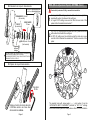
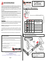
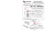
MAS (Micro Adjustment Spider) SETTING (Cont.)
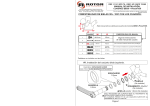
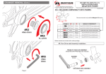
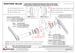
#2. Instalación del conjunto biela derecha.
CAJA 68mm: ESPACIADOR 8,5mm
CAJA 73mm: ESPACIADOR 5,5mm
*
*
RODAMIENTO, 30x42x7
(No incluido)
CIRCLIP
(No incluido)
Engrase
el cono
del eje
*
ESPACIADOR
11.5mm
*
!
SELLO, ancho 1.6mm
(Not included)
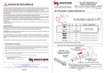
Read and fully understand Q-Ring´s manual before installation
1
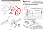
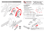
For “regular” OCP settings place the bolts and nuts in positions
marked with number 1 as shown in the next figure.
In “regular” OCP setting, screw one bolt from the inner side of the
spider into the threaded hole marked as 1*.
2
For “OCP+1/2" settings place the bolts and nuts in positions marked
with number 2 as shown in the next figure.
In OCP+1/2 settings one hole is hidden under the crank arm, screw
one bolt into this threaded hole marked as 2* from the inner side of the
spider.
1
SÓLO NECESARIO CON CUADROS BB30 (EL RODAMIENTO
SE INSTALA DIRECTAMENTE EN EL CUADRO).
EN CUADROS DE PRESS FIT 30 LA CAZOLETA SUSTITUYE AL
RODAMIENTO, SELLO Y CIRCLIP.
2
1
2
2
2
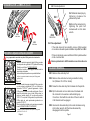
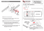
#3. Fijación del cojunto biela derecha.
1
1
2*
1
2
1*
2
Allen 8mm
35 Nm
1
2
1
1
Apriete el tornillo de la biela derecha
a 35 Nm usando una llave allen
dinamométrica de 8mm.
Página 2
1
2
2
The marked holes with arrow peaks ( ▲ ) and number 2 are the
“ALTERNATIVE BOLT PLACEMENT” positions for “OCP +1/2" settings.
Check that bolts are placed in those positions after OCP+1/2 installation.
Page 5