1
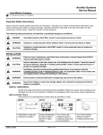
AB5000
user’s guide
because your money counts
professional bill counter
user’s guide
manual de usuario
pg. 3
pág. 27
WARNING
Before turning the power on, please make sure that there are no
objects obstructing the operation of the rollers and wheels. When
operating this unit, please wait 5 minutes to allow the UV system
reach its maximum detection capability
AccuBANKER and its logo are registered trademarks or trademarks of Hilton Trading Corp. All Rights Reserved.
2
Thank you for purchasing this Professional Bill Counter.
This User’s Guide compiles all the relevant instructions
about the use and operation of the AB5000 PLUS.
We recommend the new user to read this manual
thoroughly, in order to get familiarized with the controls
and operation of the unit.
AB5000 PLUS PROFESSIONAL BILL COUNTER
Getting Started
4-8
Table of Contents
9
Parts
10-11
Function Controls
12-14
Operation
15-18
UV Lamp Replacement
19-24
Error Message Display
25
Specifications
26
3
Getting Started
AB5000 PLUS Features
One of the most advanced bill counters available today,
the AB5000 PLUS has been the talk of the industry
since we first introduced it in the market. Equipped with
a fully computerized mechanism, the AB5000 PLUS
boosts variable counting speeds, digital task
programming and dual means of counterfeit detection.
It is also equipped with an acrylic molded cover to
protect the user from the dust generated by the fast
counting action. Stylish yet affordable, the AB5000
PLUS will make the most efficient and cost-effective
device to help in counting, sorting and detecting
counterfeit currency in any environment where moneys
are used.
!
!
!
!
!
!
!
!
!
!
!
4
Convenient and easy to operate
Fast and accurate counting
Two starting modes (Auto/Manual)
Three counting speeds (fast, normal and slow)
Three changeable banknote condition levels
Batch and free counting mode
Addition counting mode
Detection of paper bill size
Counterfeit bill detection systems (magnetic and UV)
Dust proof cover
Error/trouble message display
Features
Getting Started
Important Safety Instructions
When using the bill counter, basic safety precautions should always be followed to
reduce the risk of fire, electric shock or injury to persons, including the following:
Warning
Do not use this product in areas where it may be
exposed to water or other liquids.
Unplug this product from the wall outlet before
cleaning. Do not use liquid or aerosol cleaners. Use
a damp cloth for cleaning.
To reduce the risk of electric shock, do not
disassemble this product. Take it to qualified
service personnel when service or repair work is
required. Opening or removing covers may expose
you to dangerous voltages or other risks. Incorrect
re-assembly can cause electric shock when the
appliance is subsequently used.
Caution
When unplugging the power plug, do not pull it by
the cord but rather grip the plug to pull it out. Not
following these instructions may result in electric
shock, fire or damage to the unit.
Do not use the unit if the power cord is damaged or
if the plug socket contact is loose. Not following
these instructions may result in electric shock, fire
or other hazards.
Do not place heavy objects over the cord and do
not bend it excessively since it could get damaged.
Not following these instructions may result in
electric shock, fire or other hazards.
When not using the unit for a long period of time,
remove the power plug from the wall outlet.
Only use the cable provided with the unit. The use
of other cables may result in electric shock, fire or
cause serious damage to the unit.
Do not operate the unit in areas with high
temperature or high humidity since it may prevent
it from working correctly.
Safety Instructions
5
Getting Started
Other Safety Considerations
1
Read and understand all of the instructions.
2
Follow all warnings and instructions marked on
the unit.
3
The slots and openings in the back or bottom of
the case, are provided for ventilation, to protect
the unit from overheating. These openings
should never be blocked or covered by placing
the product on the bed, sofa, rug, or similar
surfaces. This product should never be placed
near or over a radiator or heat register. This
product should not be placed in a built-in
installation unless proper ventilation is provided.
4
This product should be operated only from the
type of power source indicated in the user guide.
If you are not sure of the type of power supply
in your location, consult your dealer or local
power company.
5
This product is equipped with a three wire
grounding type plug, a plug having a third
(grounding) pin. This plug will only fit into a
grounding type power outlet. This is a safety
feature. If you are unable to insert the plug into
the outlet, contact your electrician to replace the
outlet. Do not try to defeat the safety purpose of
the grounding type plug.
6
6
Never push objects of any kind into the unit
through case slots, since they may touch
dangerous voltage points or shortcut parts,
resulting in a risk of fire or electric shock. Never
spill liquids of any kind on the product.
7
Unplug this product from the wall outlet and
refer servicing to qualified service personnel
under the following conditions:
!
!
!
!
!
!
When the power supply cord or plug is
damaged or frayed.
If liquid has been spilled into the unit.
If the unit has been exposed to rain or water.
If the unit does not operate normally by
following the operating instructions. Adjust
only those controls that are covered by the
operating instructions. Improper adjustment
of other controls may result in damage and
will often require extensive work by a
qualified technician to restore the product to
normal operation.
If the product has been dropped or the case
has been damaged.
If the product shows a noticeable change in
performance.
Safety Considerations
Getting Started
Box Contents
When opening the box verify that all the items described below have been included. If any item is
missing or damaged, contact the dealer where you purchased the unit.
Bill Counter Unit
Power Cable
UV Lamp
Only use the cable
provided with the product.
The use of other cables
may result in electric
shock, fire or cause serious
damage to the unit.
A box containing one (1) UV
lamp replacement. (For
directions about changing
the UV lamp go to page 19)
Box Contents
Other Items
Plastic cover, manual and
Warranty Card
7
Getting Started
Cleaning and Maintenance
1
Since the sensors in this unit are of the optical
type, counting errors may be caused by paper
particles, dust, dirt, stain, and other materials
that get stuck or clutter the counting sensors.
Also, it may be difficult to start the counting
operation if the repeat and/or the auto-start
sensor are cluttered with dust, paper particles,
etc.
2
For effective operation of the unit, it is necessary
to clean all the sensors shown in the picture on
the right with a dry brush, periodically or as
needed.
3
Due to the optical nature of the sensors in the
unit, exposure to any direct light source should
be avoided.
4
Since the machine uses a roller friction system,
keep small objects such as pins, clips, necklaces
or hair away from it to prevent them to get stuck
in the mechanism. Clean the hopper and stacker
with a dry brush or cloth, periodically or as
needed. Keep the UV lamp clean by pulling and
pushing the UV lamp cleaning-shaft.
8
Attention!
Clean the unit only when the power is OFF.
Do not use chemicals/abrasives to clean the
unit.
SENSORS
Cleaning and Maintenance
Contents
Table of Contents
Parts
Function Controls
Operation
Turning the power ON
Bill physical condition selector
Counting mode
Addition mode
Halting and resuming mode
Auto/MNL (manual) starting mode
Thickness adjustment control
Dust proof cover function
Size of currency detection function
Counterfeit bill detection
- UV detection function
- Magnetic detection function
UV Lamp Replacement
Error Message Display
Specifications
Table of Contents
10
12
15
15
15
15
16
16
16
16
16
17
17
17
18
19
25
26
9
Parts
Parts
Hopper
Place the bills to be counted in this compartment.
Counting Guides
Aid to help position the bills correctly to be fed into the unit.
UV Lamp Cleaning Shaft
Built-in device that cleans the UV lamp.
Thickness Adjustment Screw
Used to make the counting operation smooth. The thickness adjustment is factory defaulted
(for more information, refer to the Operation section, point 7 on page 16).
Stacker
The counted bills are stacked in this compartment.
Power Switch
Used to turn the power on or off.
Power Inlet
The supplied power cord should be connected to the power inlet first. The other end should be
connected to the AC power outlet.
Fluorescent Detection Sensitivity Adjustment Lever
The fluorescent detection sensitivity can be adjusted by sliding this lever up or down (for more
information refer to the Operation section, point 10 a on page 17).
10
Parts
Parts
Hopper
UV Lamp
Cleaning Shaft
Counting
Guides
Thickness
Adjustment Screw
Power Inlet
Power Switch
Fluorescent Detection
Sensitivity Adjustment
Lever
Parts
Stacker
11
Function
Function Controls
Restart Button
Used to initiate or reinitiate the counting
operation, or to clear an error message
shown on the display.
Banknote Physical Condition Level
Indicator Bar
A fixed bar indicates the three available
levels in the Bill Physical Condition Selector.
Keypad
This is a set of numerical keys (0-9) used to
preset optional batch groups (up to 3 digits).
Batch Function Button
Every time this button is pressed, one of the
preset quantities (10, 20, 25, 50, 100,
“blank”) will be indicated rotationally on the
Batch Number Display.
Clear Button
Used to remove the selected batch quantity
on the Batch Number Display.
MNL (manual) Button
Used to select the auto starting or the MNL
(manual) starting mode.
Add (addition) Button
Used to select or clear the Add function.
Banknote Physical Condition Selector
This button sets the bill counter sensors to
three different levels, according to how dark
or light is the ink on the bills to be counted.
(For more information, refer to the Operation
section, point 2 on page 15).
12
DD Key (Different Denomination)
This button activates a function that detects
any change in the size of the bills and selects
the detection sensitivity.
UV Detection Button (ultraviolet)
This button activates the UV detection
mechanism. This system detects counterfeit
bills by means of UV fluorescence.
MG Detection Button (magnetic)
This button activates the magnetic
detection mechanism. This system detects
counterfeit bills by verifying magnetic
features embedded in the notes.
Function Controls
Function
Function Controls
Counting Speed Button
By pressing this key you can select the
desired counting speed setting (fast, normal
and slow).
Counting Speed Indicator
Indicates the current counting speed.
Dust Proof Cover Function Button
Activates or deactivates the dust proof cover.
Batch Number Display
This screen displays batch settings and other
messages (up to three digits/characters).
Counting Display
This screen displays the bill counting results
(up to four digits).
Auto/MNL (manual) Indicator
The indicator will be lit when the machine is
set in the MNL (manual) start mode.
Function Controls
13
DD Key (Different Denomination)
Bill Physical Condition Selector
Dust Proof Cover
Function Button
Bill Physical Condition Level Indicator Bar
Counting Number Display
Restart Button
Auto/MNL Indicator
Counting Speed Indicator
Counting Speed Button
Clear Button
Batch Number
Display
Batch Function Button
MNL (manual) Button
Keypad
Add Button
UV detection Button (ultraviolet)
MG detection Button (magnetic)
14
Function Controls
Operation
Operation
Turning the Power ON
To start operating the unit, turn it on by pressing the power switch located in the back.
Bill Physical Condition Selector
The Physical Condition level indicator should be lit in the middle position when the power is on.
Change the level of this function by pressing the Bill Physical Condition Selector as follows (in case
the error message “Ed” is displayed frequently).
a) For bills that are stained or printed dark, set the level indicator in the darker position.
b) For bills that are new or printed light, set the indicator in the lighter position.
Counting Mode
The unit can work in two modes, free counting mode and batch counting mode.
Free Counting Mode
In this mode, the machine counts all the bills in the hopper. This mode will be set when the
“blank” option is selected on the Batch Number display, by pressing the Batch Function button.
Batch Counting Mode
In this mode, the machine counts the batch of bills assigned by the user. This counting mode
may be set by entering a quantity (any number up to 999 except “blank”) on the Batch Number
Display. Before beginning the counting function, use the Batch Function button or keypad to
set the desired quantity or the “blank”, and then begin counting normally.
Note:
In the auto starting mode, the next counting operation will start automatically by only removing the
counted bills from the stacker. In case the counting stops before the preset number has been reached,
refill the hopper. The machine will continue counting automatically.
Operation
15
Operation
Addition Mode
While working under the addition mode, the cumulative total is shown on the Counting Display.
Press the ADD button to select this function (the Addition Indicator must be lit). To clear this
function, press the Add button again. This will clear the Addition indicator.
Halting and Resuming Mode
To halt the machine during the counting operation, just press the Restart button. To resume the
counting operation, press the Restart button again.
Auto/MNL (manual) Starting Mode
When the MNL (manual) button is pressed, the machine is under the MNL starting mode. In this
mode, the machine will start counting, only, when the Restart key is pressed. When the MNL button
is off, the machine is set to the AUTO starting mode. The machine will start the counting operation
automatically when the hopper is filled with bills.
Thickness Adjustment Control
The Thickness Adjustment Control is factory defaulted. However it must be changed in the
following two cases: 1) If the EC (chain) error occurs frequently, turn the Adjustment Control
counterclockwise toward “-“ (thin). 2) If the feeding operation does not go smoothly due to new
bills or thick paper sheets, turn the Adjustment Control clockwise toward “+” (thick).
Dust Proof Cover Function
Press the Dust Proof Cover Function button to select this function (the Dust Proof Cover indicator
must be lit). When this function is selected, the Dust Proof Cover will close automatically before the
counting operation begins. The cover automatically opens, in case the counting stops. To clear this
function, press the Cover button until the indicator turns off.
16
Operation
Operation
Size of Currency Detection Function (Different Denomination Detection Function)
Through this function, the size of the first counted bill will be memorized, and if a smaller one is
detected, the machine will stop and the message “dd” will be shown on the Batch Number
Display. This function can be enabled or disabled. The sensitivity of the DD function can be
changed by pressing the DD button function to select the desired DD function code, as shown
on the following table.
Code
d-0
d-2
d-3
d-4
Function
DD function unavailable
2+1mm tolerance sensitivity
3+1mm tolerance sensitivity
4+1mm tolerance sensitivity
Note:
Every time you press the DD key, the function code will be shown on the Batch Display for one
second and the DD Indicator will be lit. If the machine stops while operating under this function,
verify the last two counted bills. Take away the smaller bill, press the RESTART button to clear the
error message and recount all the bills.
Counterfeit Bill Detection Function
When operating in this mode, the machine will stop when a counterfeit bill is detected.
A) UV Detection Function (ultraviolet)
Counterfeit bills that do not generate fluorescence under the ultraviolet rays, can be
detected when this function is selected. The machine will stop and the error message “CF1”
will be shown on the Batch Number Display. The UV detection function may be selected by
pressing the UV button (the UV Indicator will be lit).
Operation
17
Operation
Note:
The UV Indicator can be lit in two colors. When in red, it means that the UV Function is normal.
When the indicator is green, it means that the brightness of the UV lamp is low. In this case, you
must select a proper fluorescent detection sensitivity to get the desired results. This can be
achieved, by sliding the sensitivity lever located in the back of the unit to the highest position (the
fluorescent detection sensitivity has four positions). If the machine stops because a counterfeit bill
is detected, remove it, press the RESTART button to clear the error message and recount all the bills
placed in the stacker.
b) MG Detection Function (magnetic)
In this mode, the machine will detect counterfeit bills using magnetic detection sensors.
When a counterfeit bill is detected, the machine will stop and the error message “CF2” will
be shown on the Batch Number Display.
The MG detection function may be selected by pressing the MG button (the MG indicator
will light up). To clear the MG function, press the MG button until the indicator turns off.
Note: When the machine stops because a counterfeit bill is detected (the last one on the stacker,)
take it away, press the RESTART key to clear the error message and recount all the bills placed in the
stacker.
Note: The ultraviolet and magnetic detection systems integrated in the AB5000 PLUS are valuable
instruments to help the user verify the legitimacy of bills. However, the AB5000 PLUS, like all other
counters with integrated detectors in the market, cannot guarantee the legitimacy of any bill
analyzed by it due to the unpredictable techniques or advances that counterfeiters may introduce.
18
Operation
Replacement
UV Lamp Replacement
The AB5000 PLUS includes a spare UV lamp that the user may exchange in case the original one
burns out or breaks. Make sure the original lamp is burnt out or broken before replacing the part.
Follow these instructions carefully:
Note: before maintaining the machine, adjusting any part, or replacing any piece, make sure that
the unit is turned OFF and unplugged from the power outlet.
Manually, unscrew the cleaning rod located on the right side of the unit when seen from the back
(turn counter clockwise to unscrew and vice versa) (see figure 1).
Using a screwdriver, remove the screws located in the back of the unit (see figure 2).
Figure 1
Figure 2
UV Lamp Replacement
19
Replacement
Do the same with the screws located on both sides of the unit (see figure 3).
Carefully remove the back plastic cover (see figure 4).
Figure 3
20
Figure 4
UV Lamp Replacement
Replacement
Remove the two screws that hold the back metal plate (see figure 5). Once removed, carefully
remove the metal plate and place it on the side. Do not disconnect the wirings from the metal
plate. Just place the plate aside and attached to the wirings that may connect it to the unit (see
figure 6).
Figure 5
Figure 6
Unscrew both sides
UV Lamp Replacement
21
Replacement
Locate the UV lamp (see figure 7). Rotate it with your fingers until you can pull it from its housing
(see figure 8). Once free, remove the cleaning device attached to it (see figure 9). Insert the new
UV lamp into the cleaning device. Place the UV lamp -with the cleaning device attached- in the
housing. Rotate it until it is secure in the housing.
Figure 7
Figure 8
Figure 9
Make sure the
cleaning device
points in the right
direction when
inserting the new
lamp
22
UV Lamp Replacement
Replacement
Grab the back plastic cover and place it in its original position. Screw it back to the unit.
Unscrew the top plastic cover (see figure 10). Place your thumb on the thickness adjustment
screw. Pull it back (see figure 11).
Figure 10
Figure 11
Unscrew both
sides
UV Lamp Replacement
23
Replacement
While pulling the thickness adjustment screw back, remove the plastic cover by grabbing it from
the center (see figure 12). Once removed, insert the cleaning rod and visually, screw it back to the
cleaning device. You may simplify the procedure by holding the cleaning device with a screwdriver
(see figure 13). Once securely screwed, place the plastic cover where it should fit, pull the
thickness adjustment screw back and refit the plastic cover. Once fitted in its original position,
screw the top cover back.
Figure 12
Figure 13
You may simplify the
procedure by holding
the cleaning device
with a screwdriver
24
UV Lamp Replacement
Error Messages
Error Message Display
ERROR
MEANING
CAUSE
SOLUTION
EJ
Jam
Bill is jammed
in the machine
Remove notes placed in the hopper
(the machine will try remove the
jammed bill. If not, you may
have to remove it by hand)
ED
Double
More than two bills
are detected or a bill
is detected that is too
densely printed
compared to a
standard bill
* Remove all the bills in the stacker
* Press the “RESTART” button to clear
the error code
* Recount all the bills
EC
Chain
More than two bills
fed in chain
EO
Batch over stop
The counting result
is larger than the
batch
DD
DD bill(s)
Abnormal bills are
mixed
CF1 (UV)
CF bill
detection
CF2 (MG)
CF bill
detection
Error Messages
Refer to Size of Currency
Detection Function section
(point 9, page 17)
Refer to the Counterfeit Bill
Detection Function section
(point 10, page 17)
25
Specifications
Specifications
Ambient Temperature:
Ambient Humidity:
Feed System:
Hopper Capacity:
Stacker Capacity:
Size of Countable Notes:
Thickness of Countable Notes:
Counting Number Display:
Batch Preset Number Display:
Power Source:
Power Consumption:
Dimensions:
Weight:
Denomination Detection Sensitivity:
Counting Speed:
- Fast
- Normal
- Slow
26
32°F - 104°F (0°C - 40°C)
30% - 80%
Roller Friction System
200 sheets/new bills
100 sheets/old bills
200 sheets/new bills
100 sheets/old bills
50mm x 100mm - 100mm x 185mm
0.06mm x 0.12mm
Four digits LED (large)
Three digits LED (small)
Single Phase 220 Volts + 10% RAM, 50 - 60 Hz
Single Phase 110 Volts + 10% RAM, 50 - 60 Hz
< 60 W
11” x 9” x 8” (275mm x 227mm x 195mm)
15.5 lb (7.0 kg)
2/3/4 + 1mm
1500 bills/min (approx.)
1000 bills/min (approx.)
700 bills/min (approx.)
Specifications
Gracias por comprar esta Contadora de Billetes
Esta guía para el usuario contiene información pertinente
al uso y operación de la AB5000 PLUS.
Recomendamos que la lea en su totalidad para que se
familiarice con los controles y operación de la unidad.
CONTADORA DE BILLETES AB5000 PLUS
Para Empezar
28-32
Índice
33
Partes
34-35
Controles
36-38
Operación
39-42
Reemplazo de la Lámpara UV
43-48
Solución a los Mensajes de Error
49
Especificaciones
50
27
Para Empezar
Características de la AB5000 PLUS
La AB5000 PLUS es una de las contadoras de billetes
más avanzadas del mercado. Esto se debe a su sistema
de procesamiento de funciones, que es completamente
computarizado, y que le permite operar en diversas
modalidades tales como conteo, adición, agrupación,
etc. La identificación de billetes falsos se realiza
mediante dos sistemas: ultravioleta y magnético.
Además, posee una cubierta que se cierra para
proteger al usuario del polvo generado por la acción de
conteo. Usted quedará sorprendido con su versatilidad
y fácil operación, indispensables en cualquier lugar
donde se maneje dinero.
!
!
!
!
!
!
!
!
!
!
!
Conveniente y fácil de operar
Conteo rápido y preciso
Dos modos de arranque (automático y manual)
Tres velocidades de conteo
Tres niveles de detección variables de acuerdo a la condición
de los billetes
Modo de conteo con o sin agrupamiento
Modo de conteo con adición de totales
Detección de billetes con denominaciones diferentes
Sistema detector de billetes falsos
Cubierta contra el polvo
Pantalla que muestra mensajes de error
28
Características
Para Empezar
Instrucciones Importantes de Seguridad
Al usar la contadora de billetes deberán tomarse estas precauciones básicas de
seguridad para evitar riesgos de incendio, descarga eléctrica o daños a terceros.
Advertencia
No opere este producto en lugares donde pueda
estar expuesto al agua o cualquier otro líquido. No
opere este equipo en lugares húmedos.
Antes de comenzar a limpiar la unidad,
desenchúfela de la toma de alimentación eléctrica.
No utilice limpiadores líquidos o en aerosol. Use
únicamente un paño humedecido con agua.
Para reducir el riesgo de descarga eléctrica, no
desmantele la unidad. Cuando sea necesaria una
reparación, llévela a un centro autorizado de
servicio. Abrir o quitar la cubierta puede exponerlo
a altos voltajes u otros riesgos. El ensamblaje
incorrecto puede causar una descarga eléctrica
cuando se vuelva a utilizar la unidad.
Utilice únicamente el cable que viene con la unidad.
El uso de otros cables puede resultar en descarga
eléctrica, fuego o daño irreparable a la unidad.
Precaución
Cuando desenchufe la unidad de la toma de
energía, no lo haga halando el enchufe por el
cable, sino por la clavija. No seguir estas
instrucciones puede resultar en riesgo de descarga
eléctrica, fuego o daño a la unidad.
No utilice esta unidad si el cable eléctrico está
dañado o el contacto en la clavija esta suelto. No
seguir estas instrucciones puede resultar en
descarga eléctrica, fuego u otros peligros.
No coloque objetos pesados sobre el cable y no lo
doble excesivamente porque puede dañarlo. No
seguir estas instrucciones puede resultar en
descarga eléctrica, fuego u otros peligros.
Cuando no use la unidad por un tiempo
prolongado, desenchufe la clavija de la toma de
alimentación.
No operar esta unidad en áreas con altas
temperaturas o excesiva humedad ya que puede
resultar en un mal funcionamiento de la misma.
Instrucciones de Seguridad
29
Para Empezar
Otras Consideraciones de Seguridad
1
Lea y entienda todas las instrucciones.
2
Siga todas las precauciones e instrucciones
señaladas en la unidad.
3
Las aberturas y rejillas en la parte posterior y base
de la contadora, sirven para ventilar la unidad.
Estas entradas no deben ser obstruidas o cubiertas
colocando la contadora sobre una cama, sofá,
alfombra u otra superficie similar. Este producto
nunca deberá ser colocado cerca o encima de una
estufa o sistema de calefacción. Este producto no
deberá ser puesto en un compartimiento que no
tenga la ventilación apropiada.
6
Nunca inserte objetos de ningún tipo por las
rejillas o aberturas de la unidad ya que podrían
tocar partes energizadas resultando en descarga
eléctrica, fuego o daño a la unidad. Nunca
derrame líquidos de ningun tipo sobre la unidad.
7
Desenchufe la unidad de la toma de
alimentación y llévela a un centro autorizado de
servicio en los siguientes casos:
!
!
!
4
5
30
Este producto deberá ser operado utilizando el
voltaje correcto indicado en el manual de usuario.
Si no está seguro del tipo de voltaje, consulte al
distribuidor o a su compañía proveedora de
electricidad.
Este producto está equipado con un cable eléctrico
de tres clavijas con conexión a tierra. Este enchufe
encaja únicamente en una toma de corriente triple
con conexión a tierra. Esta es una característica de
seguridad. Si usted no puede insertar el enchufe
correctamente, no lo fuerce, contacte a un
electricista para reemplazar la toma de corriente
por una adecuada al tipo de enchufe.
!
!
!
Cuando el cable eléctrico esté dañado o
gastado.
Si algún líquido ha sido derramado sobre la
unidad.
Si el producto ha sido expuesto al agua u
otros líquidos.
Si el producto no funciona correctamente aún
siguiendo las instrucciones (ajuste solamente
los controles y partes mencionados en este
manual. No trate de manipular otros
aditamentos ya que podría dañar la unidad, lo
que requerirá de técnicos calificados para
restaurar el producto a su condición original).
Si el producto ha sufrido una caida o golpe
fuerte.
Si el producto muestra algún cambio notorio
en su funcionamiento.
Otras Consideraciones
Para Empezar
Contenido de la Caja
Compruebe que todas las partes descritas en esta página estén presentes al abrir la caja. Si falta
algún artículo, o hay alguno que esté dañado, póngase en contacto con el concesionario donde
adquirió la contadora de billetes.
Cable eléctrico
Lámpara de luz UV
Utilice únicamente el cable
que viene con la unidad. El
uso de otro tipo de cables
eléctricos puede resultar en
descarga eléctrica, fuego o
causar daño irreparable a la
unidad.
Una caja que contiene una
(1) lámpara de luz UV de
repuesto. (Para indicaciones
de como reemplazar la
lámpara UV vaya a la pág.
43)
Contadora de billetes
Contenido
Otros artículos
Cubierta de plástico,
manual y tarjeta de
garantía.
31
Para Empezar
Limpieza y Mantenimiento
1
Si partículas de polvo, suciedad, etc, se adhieren a
los sensores de conteo, pueden ocurrir errores en
su funcionamiento, o puede que sea difícil comenzar
la operación de conteo.
2
Para obtener mejores resultados es necesario
limpiar con una brocha (periódicamente o cuando
sea necesario) todos los sensores mostrados en la
imagen de la derecha.
3
La máquina utiliza sensores ópticos, así que
sugerimos mantener el equipo fuera del alcance
directo de cualquier fuente directa de luz.
4
La unidad utiliza un sistema de rodillos de fricción,
por esta razón, objetos tales como alfileres,
presillas, cadenas y cabello deben ser mantenidos
lejos de la misma para evitar que sean
transportados hacia el interior. Mantenga limpios el
alimentador y la bandeja receptora, usando para
ésto una brocha.
5
Es importante limpiar la lámpara UV usando la
varilla que está al costado de la unidad. (Ésto se
logra halándola hacia afuera y empujándola
nuevamente hacia el interior de la unidad).
32
Atención!
Desconecte la unidad antes de limpiarla.
No utilice productos químicos ni abrasivos
para limpiar la unidad.
SENSORES
Limpieza y Mantenimiento
Índice
Índice
Partes
Controles
Operación
Encendido
Botón para regular detección de acuerdo al estado físico de los billetes
Selección del modo de conteo
Función de conteo mediante acumulación de totales
Detención y continuación del conteo
Modos de conteo automático y manual
Tornillo de ajuste del grosor de alimentación de los billetes
Activación de la cubierta a prueba de polvo
Detección de billetes por tamaño (diferente denominación)
Detección de billetes falsos
- Detección ultravioleta (UV)
- Detección magnética (MG)
Reemplazo de la Lámpara UV
Solución a los Mensajes de Error
Especificaciones
Índice
34
36
39
39
39
39
40
40
40
40
40
41
41
41
42
43
49
50
33
Partes
Partes
Alimentador
Los billetes a contar deben ser colocados aquí.
Guías de Conteo
Se utilizan para alinear los billetes que entrarán en el sistema alimentador.
Varilla Limpiadora de la Lámpara Ultravioleta
Se utiliza para limpiar la lámpara ultravioleta que se encuentra en el interior de la unidad.
Tornillo de Ajuste del Grosor de Alimentación de los Billetes
Se usa para ajustar el sistema de acuerdo con el grosor de los billetes a contar. Este control ha
sido preajustado por el fabricante(para más información refiérase al punto 7 en la sección
“Operación”, página 40).
Bandeja Receptora
Los billetes contados son acumulados en la bandeja receptora.
Interruptor General
Pone en funcionamiento la unidad.
Entrada para Alimentación Eléctrica (enchufe)
El cable de alimentación que acompaña a la unidad se conecta en esta entrada.
Selector de Sensibilidad para la función de Detección Ultravioleta
La sensibilidad de detección ultravioleta puede variarse mediante este selector (para más
información refiérase a “Operación”, punto 10 a, página 41).
34
Partes
Partes
Alimentador
Guías de conteo
Varilla limpiadora de
la lámpara UV
Tornillo de ajuste del
grosor de alimentación
de los billetes
Entrada para
alimentación
eléctrica (enchufe)
Interruptor
general
Bandeja receptora
Partes
Selector de sensibilidad para
la función de detección
ultravioleta
35
Controles
Controles
Botón RESTART
Se usa para iniciar la operación de conteo o
borrar un mensaje de error que aparezca en
la pantalla.
Teclado Numérico
Este es un conjunto de teclas numéricas (del
0 al 9) que se utilizan para preseleccionar la
cantidad de billetes a agrupar (hasta 3
dígitos).
Botón de Cancelación
Elimina en la pantalla el número preseleccionado de agrupamiento.
Botón MNL(manual)
Selecciona el modo de arranque: automático
o manual.
Botón de Sumar
Activa o desactiva la función de sumar.
Botón para Regular Detección de
Acuerdo al Estado Físico de los Billetes
Se utiliza para regular la detección de billetes
de acuerdo con el estado de la impresión de
los mismos (para más detalles refiérase a “Operación”
punto 2).
36
Controles
Indicador de Selección del Estado Físico
de los Billetes
Indica el nivel seleccionado con el botón
regulador de detección de acuerdo al estado
físico de los billetes.
Botón de Agrupación
Cada vez que esta tecla es presionada una de
las opciones de agrupamiento de billetes a
contar (10, 20, 25, 50, 100, “en blanco”)
aparecerá en la pantalla.
Botón DD (diferente denominación)
Configura la unidad para detectar
denominaciones (por tamaño) y seleccionar
la sensibilidad de detección.
Botón de Detección Ultravioleta (UV)
Permite que la unidad detecte billetes falsos
mediante el uso de luz ultravioleta.
Botón de Detección Magnética (MG)
Activa la unidad para reconocer los billetes
falsos mediante el sistema de detección
magnética.
Controles
Controles
Botón Regulador de Velocidad
Permite escoger la velocidad de conteo
deseada (rápida, normal o lenta).
Indicador de Velocidad
Indica la velocidad seleccionada para el
conteo de billetes.
Botón Activador de la Cubierta a
Prueba de Polvo
Cierra y abre la cubierta protectora a
prueba de polvo.
Pantalla de Agrupamiento
Muestra el número de agrupamiento
seleccionado y mensajes de error (hasta 3
dígitos).
Pantalla de Cantidades Contadas
Muestra los resultados del conteo de
billetes (hasta 4 dígitos).
Indicador Auto / MNL(manual)
Éste se iluminará cuando la unidad esté
funcionando en el modo de arranque
MNL(manual).
Controles
37
Botón DD (diferente denominación)
Botón para regular detección de acuerdo al estado físico de los billetes
Indicador de selección del estado físico de los billetes
Pantalla de cantidades contadas
Botón activador
de la cubierta a
prueba de polvo
Indicador Auto/MNL
Botón RESTART
Indicador de velocidad
Botón regulador de
velocidad
Pantalla de
agrupamiento
Botón de cancelación
Botón de agrupación
Botón MNL (manual)
Botón de sumar
Botón de detección UV (ultravioleta)
Botón de detección MG (cabezal magnético)
38
Controles
Teclado numérico
Operación
Operación
Encendido
El interruptor general de encendido de la unidad se encuentra en la parte posterior de la misma.
Botón para Regular Detección de Acuerdo al Estado Físico de los Billetes
Cuando la unidad se pone en funcionamiento, el indicador de detección de condición de billetes
debe estar iluminado en la posición intermedia. En caso de que el mensaje de error “Ed” aparezca
frecuentemente en la pantalla, cambie el nivel del mismo oprimiendo el botón para regular la
detección de acuerdo al estado de los billetes usando las siguientes reglas:
a) Para billetes manchados -con impresión oscura-, coloque el indicador luminoso en la posición
más oscura de la barra.
b) Para billetes que estén nuevos -con impresión clara-, coloque el indicador luminoso en la
posición más clara de la barra.
Selección del Modo de Conteo
La unidad puede trabajar en dos modalidades: libre y por agrupamiento.
Modo de conteo libre: En este modo la unidad cuenta todos los billetes colocados en el
alimentador sin detenerse. Para activar esta modalidad, seleccione “en blanco” (pantalla en
blanco) en la pantalla del número de agrupamiento presionando el botón correspondiente.
Modo de conteo por agrupamiento: En este modo la unidad cuenta la cantidad de billetes
que usted haya preseleccionado. Escoja cualquier cantidad hasta 999 (excepto “en blanco”).
Antes de comenzar el conteo use la tecla de agrupamiento o el teclado para seleccionar el
número deseado y entonces comience el conteo normalmente.
Nota: Cuando la unidad esté en el modo de conteo automático, el próximo conteo comenzará
automáticamente con sólo quitar los billetes ya contados de la bandeja receptora.
Operación
39
Operación
Función de Conteo Mediante el Acumulador de Totales
Bajo esta función, el total acumulado se muestra en la pantalla del contador de billetes. Oprima la
tecla “Add” para activar esta función lo cual iluminará el indicador que está al lado del selector de
suma de billetes. Para desactivar esta función, presione nuevamente la tecla “Add”. Esta acción
apagará el indicador.
Detención y Continuación del Conteo
Para detener la unidad durante la operación de conteo, solamente oprima la tecla “RESTART”.
Para continuar el conteo oprima nuevamente la tecla “RESTART”.
Modos de Conteo Automático y Manual
Cuando se ilumina el indicador MNL(manual), la unidad está funcionando en el modo manual. En
este caso, comenzará a contar solamente cuando se presione la tecla “RESTART”.
Cuando el indicador MNL(manual) esté apagado, la unidad estará en el modo de arranque
automático. En este modo, la unidad contará automáticamente los billetes que sean colocados en
el alimentador.
Tornillo de Ajuste del Grosor de Alimentación de Billetes
El tornillo de ajuste de alimentación de billetes ha sido preajustado por el fabricante, pero debe
recalibrarse en los siguientes dos casos: 1) El mensaje de error “EC” (billetes encadenados) aparece
frecuentemente. Gire el tornillo en contra de las manecillas del reloj hacia “-“ (fino). 2) La operación de
alimentación no funciona con facilidad debido a que los billetes son nuevos y/o que el papel es muy grueso, gire
el tornillo en el sentido de las manecillas del reloj hacia “+” (grueso).
Activación de la Cubierta a Prueba de Polvo
Presione el botón “COVER”. El indicador de se iluminará. Bajo esta función, la cubierta a prueba de
polvo se cerrará automáticamente antes de comenzar el conteo y se abrirá en caso de que éste se
detenga. Para desactivar esta función, oprima nuevamente la tecla “COVER”.
40
Operación
Operación
Detección de Billetes por Tamaño (diferente denominación)
Mediante esta función, el tamaño del primer billete contado será memorizado y si uno más pequeño
es detectado, la unidad se detendrá y el mensaje “dd” aparecerá en la pantalla de cantidad de
agrupamiento.
Esta función puede ser seleccionada o no, y la sensibilidad puede cambiarse oprimiendo la tecla
“DD” para escoger el código de función mostrado en la siguiente tabla:
Código
d-0
d-2
d-3
d-4
Función
Función DD no disponible
2+1mm tolerancia de sensibilidad
3+1mm tolerancia de sensibilidad
4+1mm tolerancia de sensibilidad
Nota: Cada vez que usted oprima la tecla “DD” el código de funcionamiento se mostrará por espacio de
un segundo en la pantalla de agrupamiento y el indicador de “DD” se iluminará.
Cuando la unidad se detenga, operando bajo el modo de conteo rápido, verifique los últimos dos
billetes contados, saque el más pequeño, presione la tecla “RESTART” para borrar el mensaje de
error y vuelva a contar los billetes.
Detección de Billetes Falsos
La unidad se detendrá cuando detecte un billete falso y esté operando bajo cualquiera de estas
funciones:
a) Detección Ultravioleta (UV)
Un billete falso que no genere fluorescencia bajo los rayos ultravioletas puede ser detectado
cuando se activa esta función. La unidad se detendrá y el mensaje de error “CF1' aparecerá en
la pantalla de número de agrupamiento.
La función de detección ultravioleta es activada al oprimir el botón “UV” (el indicador
correspondiente debe iluminarse).
Operación
41
Operación
Nota:
El indicador UV puede iluminarse en dos colores; cuando se ilumina en rojo significa que la función “UV”
es normal. Cuando el indicador se ilumina en verde significa que la luz generada por la lámpara
ultravioleta es débil. En este caso, debe seleccionarse una sensibilidad de detección fluorescente
apropiada para obtener el resultado deseado. Ésto se logra ajustando el controlador de sensibilidad del
detector ultravioleta en una posición más alta. La sensibilidad de detección fluorescente tiene cuatro
niveles.
En caso que se detecte un billete falso y la unidad se detenga, extraiga el billete falso, oprima la tecla
“RESTART” para borrar el mensaje de error y vuelva a contar todos los billetes que estén en la bandeja
receptora.
b) Detección Magnética (MG)
Cuando esta función esté activada, la unidad detectará billetes falsos mediante detección
magnética. Cuando un billete falso sea detectado, la unidad se detendrá y el mensaje de error
“CF2” aparecerá en la pantalla de número de agrupamiento. La detección MG se selecciona
oprimiendo el botón “MG” (el indicador debe iluminarse). Para desactivar la función MG,
apriete nuevamente este botón(el indicador se desactivará).
Nota: Cuando la unidad se detenga por causa de un billete falso(el último en la bandeja receptora),
extráigalo, apriete la tecla “RESTART” para borrar el mensaje de error, y cuente otra vez todos los
billetes que estén en la bandeja receptora.
Nota: Los sistemas ultravioleta y magnético integrados en la unidad son instrumentos valiosos para
detectar billetes falsos. Sin embargo, al igual que cualquier otra contadora con detectores
incorporados, la AB5000 PLUS no garantiza la legitimidad de los billetes debido a los avances
impredecibles en falsificación de dinero.
42
Operación
Remplazo
Reemplazo de la Lámpara UV
La contadora AB5000 PLUS trae una lámpara UV de repuesto que el usuario puede reemplazar en
caso que la original se queme o rompa. Verifique que la lámpara original esté quemada o rota
antes de cambiarla.
Siga las siguientes instrucciones cuidadosamente:
Nota: antes de dar cualquier tipo de mantenimiento, ajustar alguna pieza o reemplazar algún
componente, verifique que la máquina esté apagada y desconectada de la toma de alimentación.
Desatornille manualmente la varilla de limpieza ubicada en el lado derecho de la unidad vista desde
atrás (en el sentido opuesto a las manecillas del reloj para desajustar y viceversa) (ver figura 1).
Retire los tornillos ubicados en la parte posterior de la unidad (ver figura 2).
Figura 1
Figura 2
Remplazo de la Lámpara UV
43
Remplazo
Haga lo mismo con los tornillos ubicados a ambos lados de la unidad (ver figura 3).
Cuidadosamente, retire la cubierta plástica posterior (ver figura 4).
Figura 3
44
Figura 4
Remplazo de la Lámpara UV
Remplazo
Retire los dos tornillos que sujetan la placa metálica posterior (ver figura 5). Una vez retirados,
retire la placa metálica y colóquela a un lado. No desconecte los cables. Solamente coloque la placa
a un costado, manteniéndola conectada a los cables que la unen con la unidad (ver figura 6).
Figura 5
Figura 6
Retirar los
tornillos de
ambos lados
Remplazo de la Lámpara UV
45
Remplazo
Ubique la lámpara UV (ver figura 7). Gírela con los dedos hasta que quede libre(ver figura 8). Una
vez libre, retire el dispositivo de limpieza (ver figura 9). Inserte la nueva lámpara UV dentro del
dispositivo de limpieza. Coloque la lámpara UV con el dispositivo de limpieza adjunto en la cavidad
correspondiente.
Figura 7
Figura 8
Figura 9
Verifique que el
dispositivo de
limpieza apunte en
la dirección correcta
a la hora insertar la
nueva lámpara
46
Remplazo de la Lámpara UV
Remplazo
Coloque la cubierta plástica posterior en su posición original y atorníllela a la unidad.
Desatornille la tapa plástica superior (ver figura 10). Coloque el pulgar sobre el tornillo de ajuste de
alimentación. Hálelo hacia atrás (ver figura 11).
Figura 10
Figura 11
Retire ambos
tornillos
Remplazo de la Lámpara UV
47
Remplazo
Mientras lo hala, sujete la cubierta plástica por la parte central y retírela (ver figura 12). Inserte la
varilla de limpieza y visualmente, atorníllela al dispositivo de limpieza. Puede simplificar el
procedimiento sujetando un extremo de la pieza con un desatornillador (ver figura 13). Una vez
ajustada la varilla de limpieza, coloque la tapa plástica superior donde corresponde, hale el tornillo
de ajuste de alimentación y ajuste la tapa en su posición original. Atorníllela a la unidad.
Figura 12
Figura 13
Puede simplificar el
procedimiento
sujetando un extremo
del dispositivo de
limpieza con un
desatornillador
48
Remplazo de la Lámpara UV
Mensajes
Solución a los Mensajes de Error
SOLUCION
ERROR
SIGNIFICADO
EJ
Atascado
Billete atascado en
la unidad.
Extraiga los billetes que están en el
alimentador. La unidad tratará de
expulsar el billete atascado (si esto no
ocurre, deberá retirarlo manualmente).
ED
Arrastre de
Billetes (doble)
Más de dos billetes son
detectados o uno está
impreso más oscuro en
comparación con otro
regular.
*Extraiga todos los billetes que están
en la bandeja receptora.
*Oprima la tecla “RESTART” para borrar
el mensaje de error.
*Vuelva a contar todos los billetes.
EC
Billete
encadenado
Más de un billete ha
entrado en el sistema.
EO
Exceso en la
agrupación
El resultado del conteo
es mayor que la
agrupación.
DD
Billete(s) DD
Billetes distintos
mezclados.
CF1 (UV)
Detección de
Billete Falso (UV)
CF2 (MG)
Detección de
Billete Falso (MG)
CAUSA
Mensajes de Error
Refiérase a la sección “Detección de
billetes por tamaño” (punto 9, página 41)
Refiérase a la sección “Detección de
billetes falsos” (punto 10, página 41)
49
Especificaciones
Especificaciones
Temperatura Ambiente:
Humedad Ambiental:
Sistema Alimentador:
Capacidad del Alimentador:
Capacidad de la Bandeja Receptora:
Tamaño de Billete:
Grosor de Billete:
Pantalla de Conteo de Billetes:
Pantalla de Conteo de Agrupaciones:
Fuente de Alimentación:
Consumo de Energía:
Dimensiones:
Peso:
Sensibilidad de Detección de Denominación:
Velocidad de Conteo:
- Rápida
- Normal
- Lenta
50
32°F - 104°F (0°C - 40°C)
30% - 80%
Sistema de rodillos de fricción
200 hojas / billetes nuevos
100 hojas / billetes usados
200 hojas / billetes nuevos
100 hojas / billetes usados
50mm x 100mm - 100mm x 185mm
0.06mm x 0.12mm
Indicador de cuatro dígitos (grande)
Indicador de tres dígitos LED (pequeño)
Monofásica 220 Voltios + 10% RAM, 50 - 60 Hz
Monofásica 110 Voltios + 10% RAM, 50 - 60 Hz
< 60 W
11” x 9” x 8” (275mm x 227mm x 195mm)
15.5 lb. (7.0 kg)
2/3/4 + 1mm
1500 billetes / min (aprox.)
1000 billetes / min (aprox.)
700 billetes / min (aprox.)
Especificaciones
PRECAUCIÓN
Verifique que no haya ningún objeto obstruyendo el libre movimiento de
los rodillos y ruedas receptoras de billetes antes de encender la
máquina. Encienda y espere 5 minutos antes de operarla, para que el
sistema ultravioleta alcance su máxima potencia
AccuBANKER y su logo son marcas registradas de Hilton Trading Corp.
Todos los derechos reservados.
51