1
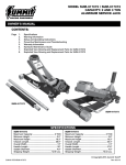
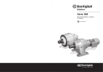
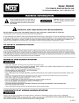
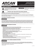
Model HJ2500
2.5 Ton Aluminum-Steel Hybrid Jack
For Technical Questions, Call: 1-800-879-7316
Warning Information
This is the safety alert symbol. It is used to alert you
to potential personal injury hazards. Obey all safety
messages that follow this symbol to avoid possible
injury or death.
WARNING
WARNING: Indicates a hazardous situation
which, if not avoided, could result in death
or serious injury.
IMPORTANT: READ THESE INSTRUCTIONS BEFORE OPERATING
BEFORE USING THIS DEVICE, READ THIS MANUAL COMPLETELY AND THOROUGHLY, UNDERSTAND ITS OPERATING
PROCEDURES, SAFETY WARNINGS AND MAINTENANCE REQUIREMENTS.
It is the responsibility of the owner to make sure all personnel read this manual prior to using the device. It is also the responsiblity of the
device owner to keep this manual intact and in a convenient location for all to see and read. Contact PowerStation, LLC for a replacement
label if your jack's label is not readable.
THE NATURE OF HAZARDOUS SITUATIONS
WARNING
The use of Portable Automotive Lifting Devices are subject to certain hazards that cannot be prevented by mechanical means, but only
by the exercise of intelligence, care, and common sense. It is essential to have personnel involved in the use and operation of the device
who are careful, competent, trained, and qualified in the safe operation of the device and its proper use when servicing motor vehicles
and their components. Examples of hazards are dropping, tipping or slipping of loads caused primarily by improperly securing loads,
overloading, off-centered loads, use on other than hard level surfaces, and using equipment for a purpose for which it was not intended.
METHODS TO AVOID HAZARDOUS SITUATIONS
WARNING
• Read, study, understand and follow all instructions before operating this device.
• Inspect the jack before each use. Do not use jack if damaged, altered, modified, in poor condition, leaking hydraulic fluid, or
unstable due to loose or missing components. Make corrections before using.
• Lift only on areas of the vehicle as specified by the vehicle manufacturer.
• Wear eye protection that meets ANSI Z87.1 and OSHA standards.
• Do not use jack beyond its rated capacity.
• This is a lifting device only. Immediately after lifting, support the vehicle with jack stands capable of sustaining the load before working on the vehicle.
• Use only on a hard level surface free from obstructions so the jack is free to reposition itself during lifting and lowering operations.
• Center load on saddle. Be sure setup is stable before working on vehicle.
• Do not move or dolly the vehicle while on the jack.
• Do not use saddle adapters or saddle extenders between the stock lifting saddle and the load.
• Do not use any adapters unless approved or supplied by PowerStation, LLC.
• Always lower the jack slowly and carefully.
• This product contains chemicals known to the state of California to cause cancer and birth defects or other reproductive harm.
Wash hands thoroughly after handling.
• Failure to heed these warnings may result in fatal personal injury and/or property damage.
CONSEQUENCES OF NOT AVOIDING HAZARDOUS SITUATIONS
WARNING
Failure to read this manual completely and thoroughly, failure to understand its OPERATING INSTRUCTIONS, SAFETY WARNINGS,
MAINTENANCE INSTRUCTIONS and comply with them, and failure to comply with the METHODS TO AVOID HAZARDOUS SITUATIONS
could cause accidents resulting in serious or fatal personal injury and/or property damage.
1
rev. 052913
INSPECTION
Visual inspection should be made before each use of the jack, checking for leaking hydraulic fluid and damaged, loose or missing parts. Any
jack which appears to be damaged in any way, is found to be badly worn, or operates abnormally MUST BE REMOVED FROM SERVICE
until necessary repairs are made.
Handle
Yoke
Handle
Handle Yoke Screw
Handle
Bumper
Handle
Yoke
Handle
Lift Arm
Cover Plate
Screws
Saddle
Upper
Handle
Hole
Rear
Casters
Front
Wheels
Lower
Handle
Bumper
Side Handle
Chassis
Lower Handle Hole
SETUP
1. Remove the 2-piece handle from box. Insert the smaller diameter end of the upper handle into the lower handle end with hole. Align the holes in the
upper and lower handles and secure them with the hex head screw provided. DO NOT OVERTIGHTEN THE SCREW as it could strip the threads in
the lower handle.
2. Grease the inside of the handle yoke so the handle will rotate freely inside the yoke. Remove the handle yoke screw. Insert the end of the lower handle
all the way in the handle yoke until it engages the release valve assembly. Secure the handle in the handle yoke by reinstalling the handle yoke screw
and tightening the screw. Rotate the handle to see if it is rotating the release valve assembly. Pull on the handle to make sure it is secured in the handle
yoke. If the release valve assembly is not rotating and/or the handle pulls out of the handle yoke, repeat step 2.
3. IMPORTANT: In most cases the jack should work normally right out of the box but it is not unusual for air to get trapped in the jack’s hydraulic system
during shipping and handling. There are several symptoms of an air trapped hydraulic system which include only partial incremental pump stroke, jack
will not lift load, jack will not sustain load or pumping feels spongy under load. The following procedure will purge air from the hydraulic system and only
needs to be done if experiencing the above mentioned conditions.
a) The saddle should be in its lowest position. Remove the four screws that secure the cover plate to the jack frame so the oil filler screw can be
removed from the hydraulic power unit reservoir tube.
b) Look inside the oil fill screw hole. You should be able to see the top of the power unit’s cylinder. The hydraulic fluid level should be no higher than
the top of the cylinder. Correct the fluid level if it is not at the proper height. CAUTION: In order to prevent seal damage and jack failure, never
use alcohol, hydraulic brake fluid, or transmission oil in the jack. Use hydraulic jack oil, a light turbine oil, Chevron Hydraulic Oil AW ISO 32 or
Unocal Unax AW 150.
c) Close the release valve by turning the handle clockwise until it stops. Pump the jack against a load of at least 500 pounds (225 Kgs). After the
load is raised to maximum height, slightly turn the handle in a counterclockwise direction so the load is very slowly lowered, while simultaneously
and quickly pumping the handle 5 or 6 full incremental pump strokes. After pumping, lower the lift arm to its full rest position.
d) Install the oil fill screw. Rotate the handle in a clockwise direction until tight and pump the lift arm to maximum height without a load. If the pumping
condition has improved, repeat steps a) through d) until all the air has been purged from the system. Reinstall the cover plate.
IMPORTANT: Before attempting to raise any vehicle, check vehicle service manual for recommended lifting surfaces.
HJ2500 User Manual
2
rev. 052913
OPERATING INSTRUCTIONS
This is the safety alert symbol used for the OPERATING INSTRUCTIONS section of this manual to alert you to potential personal
injury hazards. Obey all instructions to avoid possible injury or death. IMPORTANT: Before attempting to raise any vehicle, check
vehicle service manual for recommended lifting surfaces.
OPERATION
1. Put vehicle transmission in park or in gear and then apply the emergency brake.
To raise load: Turn the handle in a clockwise direction until tight. Position the jack under the load. Proceed to pump the handle in order to raise the lift arm to the load. As the saddle at the end of the lift arm gets closer to the load, reposition the jack so the saddle will contact the load firmly and the load is centered on the saddle. Make sure the saddle is correctly positioned. Raise the load to the desired work height. Place jack stands of appropriate capacity at the vehicle manufacturers's recommended support areas that provide stable support for the raised vehicle. DO NOT CRAWL UNDER VEHICLE WHILE LIFTING VEHICLE OR PLACING
OR REMOVING THE JACK STANDS! Once jack stands are positioned, turn the jack handle VERY SLOWLY in a counterclockwise
direction to lower the load to rest on the jack stands. Inspect the relationship between the jack stands and load to make sure the setup
is stable and safe. If the setup is not stable or safe, follow the preceding steps until corrected.
2. To lower load: Follow the procedures mentioned in "To raise load" section of the OPERATING INSTRUCTIONS in order to raise the load off the jack stands. Once the load has cleared the jack stands, remove the jack stands from under the load and away from the work area. Turn handle very slowly in a counterclockwise direction until the load is completely lowered to the ground. Once the jack's lifting saddle has cleared the load, remove the jack from under the load. CAUTION: Keep hands and feet away from the hinge mechanism of the jack.
PREVENTATIVE MAINTENANCE
This is the safety alert symbol used for the PREVENTATIVE MAINTENANCE section of this manual to alert you to potential
personal injury hazards. Obey all instructions to avoid possible injury or death.
1. Always store the jack in a well protected area where it will not be exposed to inclement weather, corrosive vapors, abrasive dust, or any other harmful elements. The jack must be cleaned of water, snow, sand or grit before using.
2. The jack must be lubricated periodically in order to prevent premature wearing of parts. A general purpose grease must be applied to
caster wheels, front axle, elevator arm, handle base pivot bolts, release mechanism and all other bearing surfaces. Worn parts resulting
from inadequate or no lubrication are not eligible for warranty consideration. See page 4 for lubrication instructions.
IMPORTANT: In order to prevent seal damage and jack failure, never use alcohol, hydraulic brake fluid, or transmission oil in the
jack. Use hydraulic jack oil, a light turbine oil, Chevron AW ISO 32 or Unocal Unax AW 150.
3. Every jack owner is responsible for keeping the jack labels clean and readable. Use a mild soap solution to wash external
surfaces of the jack but not any moving hydraulic components.
4. Inspect the jack before each use. Do not use the jack if any component is cracked, broken, bent, shows sign of damage or leaks hydraulic fluid. Do not use the jack if it has loose or missing hardware or components, or is modified in any way. Take corrective action
before using the jack again.
PROPER STORAGE
It is recommended that the jack be stored in a dry location with all wheels touching the ground on a relatively level surface.
TROUBLESHOOTING
Important: Service jacks are self-contained devices used for lifting, but not sustaining, a partial vehicular load. In accordance with ASMEPALD Load Sustaining Test: “A load not less than the rated capacity…shall not lower more than 1/8" (3.18mm) in the first minute, nor a total
of .1875" (4.76mm) in 10 minutes.” Lowering within this range is considered normal operation and is NOT a warrantable defect.
Problem
Action
1. Unit will not lift load.
Purge air from hydraulic system by following procedure under SETUP.
2. Unit will not sustain load or feels “spongy” under load.
Purge air from hydraulic system as above.
3. Unit will not lift to full height.
Purge air from hydraulic system as above.
4. Unit will not lower completely.
Check oil level. Make sure hydraulic system is not overfilled.
5. Handle tends to raise up while the unit is under load.
Pump the handle rapidly several times to push oil past ball valves in
power unit.
6. Unit still does not operate.
Contact customer service (page 6).
HJ2500 User Manual
3
rev. 052913
HYDRAULIC MAINTENANCE GUIDE
IMPORTANT: Service jacks are designed for lifting purposes only; always support raised load with jack stands.
REGULAR MAINTENANCE
MONTHLY or as necessary (depending on usage)
#1
#2
#3
#4
Using a grease gun, add grease to grease fitting in the lift arm pivot shaft.
(Use a multi-purpose NLGI type grease only.)
Lubricate all linkages and pivot points.
(Use white lithium spray grease only.)
Remove handle; lubricate handle receptacle and handle end.
(Use white lithium spray grease only.)
Lubricate both rear casters bearings and both front wheels.
(Use white lithium spray grease only.)
#3
Tighten all accessible hardware.
#1
#2
#2
#4
#2
#3
#4
#4
#2
HJ2500 User Manual
4
rev. 052913
PARTS LIST AND DIAGRAM
ITEM NO
HJ2500 User Manual
DESCRIPTION
QTY
ITEM NO DESCRIPTION
QTY
1
Locking Nut M12
4
26
Hydraulic Power Unit Assembly
1
2
Flat Washer 20
2
27
Retaining Ring 20
2
3
Front Wheel Bushing
2
28
Trunion
1
4
Front Wheel
2
29
Pin 4x40
1
5
Side Plate
2
30
Roller Bolt
1
6
Carrying Handle
2
31
Roller
1
7
Screw M8x25
4
32
Handle Yoke Screw
1
8
Washer 8
4
33
Retaining Ring 12
1
9
Retaining Ring 16
2
34
Spring Pin 3x14
1
10
Long Linkage
2
35
Screw M5x16
4
11
Front Wheel Axle
1
36
Handle Yoke
1
12
Covering plate
1
37
Handle Yoke Bolt
2
13
Spacer Bar
1
38
Stop Rod
1
14
Lift Arm Assembly
1
39
Rubber Guard
2
15
Saddle
1
40
Screw 8x25
4
16
Saddle screw
1
41
Linkage Bolt
2
17
Screw M10x20
4
42
Spring Washer 12
6
18
Tooth Washer 10
10
43
Screw M12x25
6
19
Flat Washer 10
2
44
Saddle Pad
1
20
Flat Washer 10
2
45
Trunion Screw
2
21
Rear Caster Bracket
2
46
Return Spring
2
22
Rear Caster Assembly
2
47
Release Valve Assembly
1
23
Screw M6x35
1
48
Handle Bumper
1
24
Lower Handle
1
49
Screw 10x25
6
25
Upper Handle
1
5
rev. 052913
SPECIFICATIONS
Capacity:
2.5 Ton (2,268 kgs.)
Minimum Lift Height: 3.75 in. (95 mm)
Maximum Lift Height: 18.6 in. (472 mm)
Lifting Range:
14.8 in. (376 mm)
Caster Wheel Size:
1.8 in. x .9 in. (46 mm x 23 mm)
Front Wheel Size:
2.6 in. x 1.6 in. (66 mm x 41 mm)
Saddle Diameter:
4.6 in. (117 mm)
Handle Length:
45 in. (1143 mm)
Dimensions:
24 in. x 11.9 in. x 7.9 in.
(610 mm x 302 mm x 201mm)
Net Weight:
60 lbs. (27 kgs.)
LIMITED WARRANTY
POWERSTATION, LLC WARRANTS TO ITS CUSTOMERS THAT THE COMPANY’S POWERSTATION, LLC
BRANDED PRODUCTS ARE FREE FROM DEFECTS IN WORKMANSHIP AND MATERIALS.
PowerStation, LLC will repair or replace its PowerStation, LLC branded products which fail to give satisfactory service due to
defective workmanship or materials, based upon the terms and conditions of the following described warranty plans attributed to that
specific product. This product carries a ONE-YEAR warranty. During this warranty period, PowerStation, LLC will repair or replace at our
option any part or unit which proves to be defective in material or workmanship.
Other important warranty information:
This warranty does not cover damage to equipment or tools arising from alteration, abuse, misuse, damage and does not cover any repairs
or replacement made by anyone other than PowerStation, LLC.The foregoing obligation is PowerStation, LLCs’ sole liability under this or
any implied warranty and under no circumstances shall we be liable for any incidental or consequential damages.
Note: Some states do not allow the exclusion or limitation of incidental or consequential damages, so the above limitation or
exclusion may not apply to you. If you have any questions about warranty service, please contact PowerStation, LLC. This warranty gives
you specific legal rights and you may also have other rights which vary from state to state.
1-800-879-7316
Monday - Friday 8:30am to 5:30pm EST
P.O. Box 1203
Travelers Rest, South Carolina 29690
HJ2500 User Manual
6
rev. 052913
Modelo HJ2500
Gato aluminio –acero híbrido 2.5 toneladas
Para preguntas técnicas, llame: 1-800-879-7316
INFORMACIÓN DE ADVERTENCIA
Este es el símbolo de alerta de seguridad. Se utiliza para
alertarlo de los peligros posibles de lesión personal. Obedezca todos los mensajes de seguridad que van después
de este símbolo para evitar una lesión posible o la muerte.
ADVERTENCIA
ADVERTENCIA: Indica una situación
peligrosa que, si no se evita, podría resultar
en muerte o una lesión grave.
IMPORTANTE: LEA ESTAS INSTRUCCIONES ANTES DE OPERARLO
ANTES DE UTILIZAR ESTE APARATO, LEA ESTE MANUAL COMPLETA Y CONCIENZUDAMENTE, ENTIENDA SUS PROCEDIMIENTOS DE
OPERACIÓN, ADVERTENCIAS DE SEGURIDAD Y REQUISITOS DE MANTENIMIENTO.
Es responsabilidad del propietario asegurarse que todo el personal lea este manual antes de utilizar el aparato. También es
responsabilidad del dueño del aparato mantener este manual intacto y en un lugar conveniente para que todos lo vean y lo lean.
Comuníquese con PowerStation, LLC si necesita una etiqueta de reemplazo si la etiqueta del pedestal del gato no se puede leer.
ÍNDOLE DE SITUACIONES PELIGROSAS
ADVERTENCIA
El uso de aparatos de elevación automotriz portátiles está sujeto a ciertos peligros que no se pueden evitar por medios mecánicos, sino
únicamente si se ejerce inteligencia, cuidado y sentido común. Es esencial que el personal que tenga que ver con el uso y la operación
del aparato sea cuidadoso, competente, capacitado y preparado en la operación segura del aparato y su uso adecuado cuando se dé
servicio a los vehículos automotrices y sus componentes. Ejemplos de peligros son dejarlo caer, inclinarlo o que se resbalen las cargas
a causa principalmente de que las cargas estén aseguradas de manera inadecuada, sobrecarga, cargas que no estén centradas, uso en
superficies que no sean parejas y uso del equipo para un propósito para el cuál no se fabricó.
MÉTODOS PARA EVITAR SITUACIONES PELIGROSAS
ADVERTENCIA
• Lea, estudie, entienda y siga todas las instrucciones antes de operar este aparato.
• Inspeccione el gato antes de cada uso. No use el gato si está dañado, alterado, modificado, en malas condiciones, con fuga de líquido
hidráulico o es inestable por componentes sueltos o faltantes. Haga las correcciones antes de usar.
• Levante únicamente en áreas del vehículo como lo especifica el fabricante del vehículo.
• Use protección para los ojos que cumpla con las normas ANSI Z87.1 y OSHA.
• No use el gato más allá de su capacidad clasificada.
• Este es un aparato de elevación únicamente. Inmediatamente después de levantar, apoye el vehículo con pedestales (burros) para
gatos capaces de sostener la carga antes de trabajar en el vehículo.
• Utilice sólo en una superficie pareja libre de obstrucciones para que el gato tenga espacio y se vuelva a reposicionar durante las
operaciones de elevación y descenso.
• Centre la carga en el soporte. Asegúrese de que el montaje sea estable antes de trabajar en el vehículo.
• No mueva o jale el vehículo con una carretilla mientras esté en el gato.
• No utilice adaptadores o extensores para soportes entre el cuerpo del soporte de elevación y la carga.
• No utilice ningún adaptador a menos que lo apruebe o suministre PowerStation, LLC.
• Siempre baje el gato lenta y cuidadosamente.
• Este producto contiene sustancias químicas de las que se sabe en el Estado de California que ocasionan cáncer y defectos
congénitos u otros daños de reproducción. Lávese las manos completamente después de manejarlo.
• No poner atención a estas advertencias podría resultar en lesiones personales mortales y/o daños materiales.
CONSECUENCIAS POR NO EVITAR SITUACIONES PELIGROSAS
ADVERTENCIA
Si no lee este manual completa y concienzudamente, no entiende sus INSTRUCCIONES DE OPERACIÓN, ADVERTENCIAS DE
SEGURIDAD, INSTRUCCIONES DE MANTENIMIENTO y no cumple con ellas, y si no cumple con los MÉTODOS PARA EVITAR
SITUACIONES PELIGROSAS, podría ocasionar accidentes que resulten en lesiones personales graves o mortales y/o daños materiales.
Manual de usuario HJ2500 7
rev. 052913
INSPECCIÓN
Se debe hacer una inspección visual antes de cada uso del gato, verificar fuga de líquido hidráulico y partes dañadas, sueltas o faltantes. Algún gato que
parezca estar dañado de alguna manera, se encuentra que esté muy desgastado u opere anormalmente DEBE RETIRARSE DE SERVICIO hasta que se
hagan las reparaciones necesarias.
Casquillo de
la palanca
Palanca
Tornillo de la palanca
Amortiguador
de la palanca
Casquillo de
la palanca
Palanca
Brazo elevador
Cubierta protectora
Tornillos
Soporte
Seguro de
la palanca
superior
Rear
Casters
Ruedas
delanteras
MONTAJE
Mango lateral
Chasis
Parachoques
de la palanca
inferior
Agujero del seguro de la
palanca inferior
1. Extraiga el mango de dos piezas de la caja. Inserte el extremo más pequeño del mango superior en el extremo del mango inferior con agujero. Alinee
los agujeros en los mangos inferior y superior con el tornillo hexagonal provisto. NO SOBRE APRIETE EL TORNILLO ya que se podría barrer las
roscas en el mango inferior.
2. Lubrique la parte interior del la abrazadera del mango con el fin de que el mango gire libremente dentro de la abrazadera. Inserte el extremo del
mango inferior completamente en la abrazadera del mango hasta que se encaje con el conjunto de la válvula de liberación. Sujete el mango en la
abrazadera del mango al instalar de nuevo el tornillo de la abrazadera del mango y apretarlo. Jale el mango para asegurarse que esté sujetado en la
abrazadera del mango. Si el conjunto de la válvula de liberación no está girándose y/o el mango se sale al jalarse de la abrazadera del mango, repita
el paso 2.
3. IMPORTANTE: En la mayoría de los casos, el gato debe funcionar de forma normal al sacarse de la caja, sin embargo no es incomún que se atrape
aire en el sistema hidráulico del gato durante el transporte y maniobra. Hay varias indicaciones de un sistema hidráulico con aire atrapado, lo que
incluye un recorrido incremental sólo parcial de la bomba, el gato no elevará la carga, el gato no sostendrá la carga o el bombeo se siente esponjoso
bajo la carga. El procedimiento a continuación purgará el aire del sistema hidráulico y se requiere sólo si se experimenten algunas de las condiciones
mencionadas anteriormente.
a) La silla deberá estar en su posición más baja. Extraiga los cuatro tornillos los que sujetan la cubierta protectora al armazón del gato con el fin
de poder extraer el tornillo del filtro de aceite del tubo del recipiente de la unidad de potencia hidráulica.
b) Mire adentro del agujero del tornillo de rellenado de aceite. Se debe de alcanzar a ver la parte superior del cilindro de la unidad de potencia. El
nivel del líquido hidráulico no debe estar más alto que la parte superior del cilindro. Corrija el nivel del líquido si no está a la altura adecuada.
PRECAUCIÓN: Con el fin de prevenir daños al sello y fallas del gato, nunca use alcohol, líquido para frenos hidráulicos, ni aceite para
transmisiones en el gato. Use un aceite hidráulico para gatos, un aceite ligero para turbinas, el aceite hidráulico AW ISO 32Chevron o Unax AW
150de Unocal.
c) Cierre la válvula de liberación al girar el mango en el sentido de las agujas del reloj hasta que se pare. Bombee el gato contra una carga de al
menos 500 libras. (225 kgs). Después de que se eleve la carga hasta su máxima altura, gire el mango ligeramente en el sentido de las agujas
del reloj para que la carga se baje muy lentamente, mientras que, simultáneamente y de manera rápida, se bombee el mango 5 ó 6 recorridos
incrementales de la bomba. Después de bombear, baje el brazo de levantamiento hasta que posición de reposo pleno.
d) Instale el tornillo de rellenado de aceite. Gire el mango en el sentido de las agujas del reloj hasta que esté apretado y bombee el brazo de
levantamiento hasta su m máxima altura sin carga. Si se haya mejorado la condición de bombeo, repita los pasos a) al d) hasta que se haya
purgado todo el aire del sistema. Instale de nuevo la cubierta protectora.
IMPORTANTE: Antes de intentar la elevación de cualquier vehículo, revise el manual de servicio del vehículo por superficies de levantamiento
recomendadas.
Manual de usuario HJ2500 8
rev. 052913
INSTRUCCIONES DE OPERACIÓN
Este es el símbolo de alerta de seguridad que se utiliza en la sección de INSTRUCCIONES DE OPERACIÓN de este manual para
alertarlo de posibles peligros de lesión personal. Obedezca todas las instrucciones para evitar una lesión posible o muerte.
IMPORTANTE: Antes de intentar levantar algún vehículo, verifique el manual de servicio del vehículo para ver las recomendaciones de
superficies de elevación.
OPERACIÓN
1.
Ponga la transmisión del vehículo en “Park” o meta la velocidad y luego, aplique el freno de mano. Para levantar la carga: Dé vuelta a la
palanca en dirección de las manecillas del reloj hasta que esté apretado. Posicione el gato debajo de la carga. Proceda a bombear la palanca
con el fin de levantar el brazo elevador hacia la carga. A medida que el soporte al final del brazo elevador se acerque cada vez más a la
carga, vuelva a posicionar el gato de manera que el soporte entre en contacto con la carga firmemente y la carga esté centrada en el soporte.
Asegúrese que el soporte esté posicionado correctamente. Levante la carga a la altura deseada para trabajar. Coloque pedestales (burros)
para gato de capacidad adecuada en las áreas de soporte recomendadas por el fabricante del vehículo que proporcionen apoyo estable al
vehículo levantado. ¡NO SE META DEBAJO DEL VEHÍCULO MIENTRAS ESTÉ LEVANTANDO EL VEHÍCULO O COLOCANDO O QUITANDO
LOS PEDESTALES PARA GATO! Una vez que los pedestales para gato estén posicionados, volteé la palanca del gato MUY LENTAMENTE
en sentido opuesto a las manecillas del reloj para bajar la carga y coloque en los pedestales para gato. Inspeccione la relación entre los
pedestales para gato y la carga para asegurarse que el montaje sea estable y seguro. Si el montaje no es estable o seguro, siga los pasos
anteriores hasta que se corrija.
2. Para bajar la carga: Siga los procedimientos que se mencionan en la sección “Para levantar la carga” de las INSTRUCCIONES DE
OPERACIÓN para levantar y quitar la carga de los pedestales para gato. Una vez que la carga se haya retirado de los pedestales para gato,
saque los pedestales para gato de debajo de la carga y retírelos del área de trabajo. Dé vuelta a la palanca muy lentamente en dirección
opuesta a las manecillas del reloj hasta que la carga se haya bajado completamente al piso. Una vez que el soporte de elevación del gato ya
no tenga la carga, saque el gato de debajo de la carga. PRECAUCIÓN: Mantenga las manos y pies lejos del mecanismo de bisagras del gato.
MANTENIMIENTO PREVENTIVO
Este es el símbolo de alerta de seguridad que se utiliza en la sección de MANTENIMIENTO PREVENTIVO de este manual para
alertarlo de los peligros posibles de lesión personal. Obedezca todas las instrucciones para evitar lesión posible o la muerte.
1.
Siempre guarde el gato en un área bien protegida en que no esté expuesto al clima inclemente, vapores corrosivos, polvo abrasivo o algún
otro elemento dañino. El gato debe estar libre de agua, nieve, arena o gravilla antes de usarse.
2. El gato debe lubricarse periódicamente con el fin de prevenir desgaste prematuro de las piezas. Debe aplicarse una grasa multiusos a
las ruedas, eje delantero, brazo elevador, pasadores giratorios de la base de la palanca, mecanismo de desconexión y todas las otras
superficies con rodamientos. Las piezas que se desgasten como resultado de una lubricación inadecuada o inexistente no cumplen con los
requisitos de consideración de la garantía. Vea la página 4 para las instrucciones de lubricación.
IMPORTANTE: Para prevenir el daño y la falla del gato, nunca use alcohol, líquido de frenos hidráulicos o aceite de transmisión en el gato.
Use aceite para gatos hidráulicos, un aceite ligero para turbinas, Chevron AW ISO 32 o Unocal Unax AW 150.
3. Todos los dueños son responsables de mantener las etiquetas del gato limpias y leíbles. Utilice una solución ligera con jabón para lavar las
superficies externas del gato, pero no los componentes hidráulicos que se muevan.
4. Inspeccione el gato antes de cada uso. No utilice el gato si algún componente está agrietado, roto, doblado, muestra señales de daño o
fugas de líquido hidráulico. No use el gato si tiene equipo o componentes sueltos o faltantes o está modificado de alguna manera. Tome
acción correctiva antes de utilizar el gato nuevamente.
ALMACENAMIENTO ADECUADO
Se recomienda que el gato se guarde en un lugar seco con todas las ruedas tocando el piso en una superficie relativamente pareja.
LOCALIZACIÓN Y RESOLUCIÓN DE PROBLEMAS
Importante: Los gatos de servicio son aparatos auto contenidos que se utilizan para elevar, pero no para sostener, una carga vehicular parcial. De
acuerdo con la Prueba para Sostener Cargas ASME-PALD: “Una carga que no sea menor que la capacidad clasificada…no deberá bajar más de
1/8” (3.18mm) en el primer minuto, ni un total de .1875” (4.76mm) en 10 minutos.” Bajar dentro de este rango se considera operación normal y
NO es un defecto que se pueda garantizar.
PROBLÈME
ACTION
1. Le cric ne soulève pas la charge.
Purger l’air du système hydraulique en suivant la procédure décrite
dans la section DIRECTIVES POUR LE FONCTIONNEMENT.
2. Le cric ne supporte pas la charge ou semble
flexible sous la charge.
Purger l’air du système hydraulique comme mentionné ci-dessus.
3. Ne se soulève pas à la hauteur maximale.
Purger l’air du système hydraulique comme mentionné ci-dessus. Vérifier que le niveau d’huile n’est pas trop haut ou trop
bas.
4. L’appareil ne descend pas complètement.
Vérifier le niveau d’huile. S’assurer qu’il n’est pas trop plein.
5. La poignée a tendance à remonter pendant qu’il y a une charge sur l’appareil.
Pomper la poignée plusieurs fois rapidement pour pousser l’huile pour
qu’elle dépasse le clapet à bille de l’appareil.
6. L’appareil ne fonctionne toujours pas.
Veuillez contacter le service de Pièces et de garantie énuméré
ci-dessous.
Manual de usuario HJ2500 9
rev. 052913
GUÍA DE MANTENIMIENTO HIDRÁULICO
IMPORTANTE: Los gatos de servicio están diseñados para efectos de elevación únicamente; siempre apoye la carga levantada con pedestales
para gato.
MANTENIMIENTO REGULAR
MENSUALMENTE o según sea necesario (dependiendo del uso)
#1 Con una pistola de grasa, engrase el accesorio en el eje giratorio del brazo elevador. (Utilice una grasa tipo NLGI multiusos únicamente).
#2 Lubrique todas las conexiones y puntos giratorios. (Use grasa en aerosol de litio blanco únicamente.)
#3 Quite la palanca; lubrique el receptáculo de la palanca y el extremo de la palanca. (Utilice grasa en aerosol de litio blanco únicamente.)
#4 Lubrique ambos rodamientos de las ruedas posteriores y ambas ruedas delanteras. (Utilice grasa en aerosol de litio blanco únicamente.)
Apriete todo el equipo accesible.
#3
#1
#2
#2
#4
#2
#3
#4
#4
#2
Manual de usuario HJ2500 10rev. 052913
SPECIFICATIONS
Capacidad:
2.5 toneladas (2,268 kgs.)
Mínima altura de elevación:
3.75 pulg. (95 mm)
Máxima altura de elevación:
18.6 pulg. (472 mm)
Rango de elevación:
14.8 pulg. (376 mm)
Tamaño de la rueda giratoria:
1.8 pulg. x .9 pulg. (46 mm x 23 mm)
Tamaño de la rueda delantera:
2.6 pulg. x 1.6 pulg. (66 mm x 41 mm)
Diámetro de la silla:
4.6 pulg. (117 mm)
Largura del mango:
45 pulg. (1143 mm)
Dimensiones:
24 pulg. x 11.9 pulg. x 7.9 pulg.
(610 mm x 302 mm x 201mm)
Peso neto:
60 lbs. (27 kgs.)
GARANTÍA LIMITADA
POWERSTATION, LLC GARANTIZA A SUS CLIENTES QUE LOS PRODUCTOS CON LA MARCA DE LA EMPRESA
POWERSTATION, LLC NO TIENEN DEFECTOS DE FABRICACIÓN Y DE LOS MATERIALES.
PowerStation, LLC va a reparar o reemplazar sus productos con la marca PowerStation, LLC que no proporcionen un servicio satisfactorio
por una fabricación o materiales defectuosos, con base en los términos y condiciones de los siguientes planes de garantía descritos que se
atribuyen a ese producto específico. Este producto tiene UN AÑO de garantía. Durante este periodo de garantía, PowerStation, LLC va a
reparar o reemplazar a nuestra opción alguna pieza o unidad que se demuestre que los materiales o la fabricación estén defectuosos.
Otra información importante de la garantía:
Esta garantía no cubre daños del equipo o de las herramientas que surjan por alteración, abuso, mal uso, daño y no cubre ninguna
reparación o reemplazo que haya hecho alguien que no sea PowerStation, LLC. La obligación anterior es responsabilidad única de
PowerStation, LLC según ésta o cualquier garantía implicada y bajo ninguna circunstancia será responsable de ningún incidente o daño
consecuente.
Nota: Algunos estados no permiten la exclusión o limitación de daños incidentales o consecuentes, entonces, la limitación o exclusión
anterior podría no corresponderle. Si tiene alguna pregunta sobre el servicio de garantía, por favor comuníquese con PowerStation, LLC. Esta
garantía le da derechos legales específicos y usted también podría tener otros derechos que varían de estado a estado.
1-800-879-7316
Lunes – viernes 8:30 a.m. a 5:30 p.m. Hora del este
IMPORTADO POR: IMPORTADORA PRIMEX, S.A. DE C.V. BLVD.
MAGNOCENTRO NO.4, SAN FERNANDO LA HERRADURA, HUIXQUILUCAN,
ESTADO DE MÉXICO, C.P. 52765
TEL. 5-5246-5500 R.F.C. IPR-930907-S70
Manual de usuario HJ2500 11rev. 052913