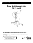
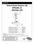
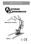
Download Manual de usuario
Transcript
User Manual Roze™Stand Assist Patient Lift FR Manuel de l'utilisateur ...................page 29 ES Manual del usario .........................página 57 NO Brukerhåndbok..............................side 85 DK Brugerhåndbog .............................side 113 DE Gebrauchsanleitung.................... seite 141 DEALER: This manual MUST be given to the user of the product. USER: BEFORE using this product, read this manual and save for future reference. For more information regarding Invacare products, parts, and services, please visit www.invacare.co.uk SYMBOL LEGEND WARNING DO NOT OPERATE THIS EQUIPMENT WITHOUT FIRST READING AND UNDERSTANDING THIS MANUAL. IF YOU ARE UNABLE TO UNDERSTAND THE WARNINGS, CAUTIONS AND INSTRUCTIONS CONTACT A QUALIFIED DEALER OR INVACARE TECHNICAL SUPPORT BEFORE ATTEMPTING TO USE THIS EQUIPMENT - OTHERWISE INJURY OR DAMAGE MAY RESULT. ACCESSORIES WARNING Invacare products are specifically designed and manufactured for use in conjunction with Invacare accessories. Accessories designed by other manufacturers have not been tested by Invacare and are not recommended for use with Invacare products. In certain instances, the use of other manufacturer’s slings may be possible. Please refer to Invacare bulletin PU001. A copy of the bulletin can be obtained from Invacare UK. Contact us on 01656 776222 or [email protected]. SYMBOL LEGEND "ATTENTION, see instructions for use". WARNING - ALWAYS be aware of the Lift Arms. Injury to the patient and/or assistant may occur. 2010 "Date of Manufacture" Device contains Lead Acid batteries. DO NOT dispose of batteries in normal household waste. They MUST be taken to a proper disposal site. Contact your local waste management company for information. WARNING - ALWAYS be aware of the Footrest, especially the patient’s position on the footrest. Injury to the patient and/or assistant may occur. Roze™Stand Assist Patient Lift 2 Part No. 1164940 TABLE OF CONTENTS TABLE OF CONTENTS SYMBOL LEGEND .............................................................................................. 2 SPECIAL NOTES ................................................................................................ 5 TECHNICAL SPECIFICATIONS ............................................................................ 6 PRODUCT PARAMETERS .................................................................................. 7 SECTION 1—GENERAL GUIDELINES ................................................................... 9 Weight Limitation ..................................................................................................................................................................9 Assembling the Lift.................................................................................................................................................................9 Using the Sling.........................................................................................................................................................................9 Operating the Lift...................................................................................................................................................................9 Lifting the Patient ................................................................................................................................................................ 10 Transferring the Patient..................................................................................................................................................... 10 Performing Maintenance.................................................................................................................................................... 10 SECTION 2—ASSEMBLY ................................................................................... 11 Assembling the Patient Lift................................................................................................................................................ 11 Assembling the Mast Assembly to the Base ............................................................................................................. 11 Assembling the Knee Pad to the Mast Assembly .................................................................................................... 11 Assembling the Foot Plate to the Mast Assembly................................................................................................... 11 Attaching the Battery Charger Mounting Bracket to the Wall ................................................................................ 12 Attaching the Battery Charger to the Mast Assembly ............................................................................................... 12 SECTION 3— OPERATION ............................................................................... 13 Operating the Patient Lift.................................................................................................................................................. 13 Locking/Unlocking the Rear Casters.......................................................................................................................... 13 Raising/Lowering the Patient Lift................................................................................................................................. 13 Closing/Opening the Legs ............................................................................................................................................. 13 Using the Emergency Stop............................................................................................................................................ 13 Activating a Mechanical Emergency Release ................................................................................................................. 14 Charging the Battery .......................................................................................................................................................... 14 SECTION 4—LIFTING THE PATIENT ................................................................. 15 Positioning the Stand Assist Lift....................................................................................................................................... 15 Lifting the Patient ................................................................................................................................................................ 16 Moving the Patient .............................................................................................................................................................. 18 SECTION 5—TRANSFERRING THE PATIENT ..................................................... 19 Transferring to a Commode............................................................................................................................................. 20 Transferring to a Wheelchair........................................................................................................................................... 21 Transferring to a Bed ......................................................................................................................................................... 21 SECTION 6—TROUBLESHOOTING .................................................................... 22 Part No. 1164940 3 Roze™Stand Assist Patient Lift TABLE OF CONTENTS TABLE OF CONTENTS SECTION 7—MAINTENANCE ........................................................................... 23 Maintenance Safety Inspection Checklist....................................................................................................................... 23 Cleaning the Sling and the Lift.......................................................................................................................................... 24 Detecting Wear and Damage........................................................................................................................................... 24 Lubricating the Lift .............................................................................................................................................................. 24 Replacing the Electric Actuator ....................................................................................................................................... 24 Replacing the Leg Actuators ............................................................................................................................................. 25 Adjusting the Knee Pad Height ........................................................................................................................................ 26 LIMITED WARRANTY ..................................................................................... 28 Roze™Stand Assist Patient Lift 4 Part No. 1164940 SPECIAL NOTES SPECIAL NOTES Signalȱwordsȱareȱusedȱinȱthisȱmanualȱandȱapplyȱtoȱhazardsȱorȱunsafeȱpracticesȱwhichȱcouldȱresultȱinȱpersonalȱinjuryȱorȱ propertyȱdamage.ȱReferȱtoȱtheȱtableȱbelowȱforȱdefinitionsȱofȱtheȱsignalȱwords. SIGNAL WORD MEANING DANGER Danger indicates an imminently hazardous situation which, if not avoided, will result in death or serious injury. WARNING Warning indicates a potentially hazardous situation which, if not avoided, could result in death or serious injury. CAUTION Caution indicates a potentially hazardous situation which, if not avoided, may result in property damage or minor injury or both. NOTICE THE INFORMATION CONTAINED IN THIS DOCUMENT IS SUBJECT TO CHANGE WITHOUT NOTICE. RADIO FREQUENCY INTERFERENCE Most electronic equipment is influenced by Radio Frequency Interference (RFI). CAUTION should be exercised with regard to the use of portable communication equipment in the area around such equipment. If RFI causes erratic behavior, PUSH the RED Emergency Stop Button IMMEDIATELY. DO NOT turn the Red Emergency Stop Button OFF while transmission is in progress. MAINTENANCE Maintenance MUST be performed ONLY by qualified personnel. Part No. 1164940 5 Roze™Stand Assist Patient Lift TECHNICAL SPECIFICATIONS TECHNICAL SPECIFICATIONS Roze™Stand Assist Patient Lift 6 Part No. 1164940 PRODUCT PARAMETERS PRODUCT PARAMETERS Maximum height capacity (k) 161 cm Lowest position (min. height) (l) 94 cm Internal width at maximum reach (q) 86.5 cm Total width (closed) external measure 67 cm Base height (clearance) 12 cm Base length 103,6 cm Overall height 124,7 cm Overall length 111,7 cm Overall width 66 cm Lifting area (height range) (m) 67 cm Minimum internal width (r) 53,8 cm Total width (open) internal measure 105 cm Total width (open) centre to centre of castors (p) 109 cm Turning radius 138 cm Height to upper edge of legs 12 cm Min. free height 4,5 cm Maximum reach at 60 cm (a) 17,5 cm Maximum reach from base (b) 41,4 cm Reach from base with legs spread to 70 cm (c) 22,2 cm Minimum Clearance of Base from the Floor (s) 3,7 cm Maximum Clearance of Base from the Floor (t) 12 cm Maximum External Length of the Base (u) 110,6 cm Maximum Internal Length of the Base (v) 62,4 cm Maximum External Width of Legs (y) 115,5 cm Minimum Internal Width of Legs (z) 104,5 cm Maximum Internal Width of Legs (w) 66,2 cm Minimum Internal Width of Legs (x) 53,4 cm Castor size (FRONT/REAR) 10 cm Sling Options Standing or Transfer Sling Material Polyester Maximum weight limitation (SWL) (patient + sling + lift arms) 200 kg (31 stone) Maximum patient weight 195 kg (30 stone) Total weight (weight out of carton) 53 kg/117 lbs Weight, Mast including battery 18,5 kg/40,8 lbs Weight, base, leg section 20,5 kg/45,2 lbs Weight, Knee Pad 7,5 kg/16,5 lbs Part No. 1164940 7 Roze™Stand Assist Patient Lift PRODUCT PARAMETERS Weight, Foot Plate 6 kg/13 lbs Operating forces of buttons Max. 5N Battery (voltage output) 24V DC mb max. 240VA (RCHBL) Charger Input (voltage supply) 100-240V AC ~ 50/60 Hz Charger Output/Charging Time 29.5V DC Max 6 hours Audio/Visual Low Battery Alarm Yes Motor Safety Devices Anti-Entrapment *Approx. Lifts per Charge (working ability) *100-200 Cycles per charge Max. current input Max. 400 mA Operating temperature 5° to 40° C Air humidity 20% to 90% @ 30 not condensing Sound pressure < 50 dB Atmospheric pressure 700 to 1060 hPa Protection class, control unit IPX4 Protection class, hand control IPX4 Protection class, motor IPX4 Insulation class II - type B Intermittens 10%, max, 2 minuttes/18 minuttes Battery capacity 2,9 Ah Manual emergency lowering Yes Electric emergency lowering/lifting Yes/Yes Expected lifetime 8 years UK Warranty Frame 3 years, Actuator/Motor 5 years, Battery 1 year *NOTE:ȱVariesȱdependingȱuponȱloadȱandȱstroke. Roze™Stand Assist Patient Lift 8 Part No. 1164940 SECTION 1—GENERAL GUIDELINES SECTION 1—GENERAL GUIDELINES WARNING SECTION 1 - GENERAL GUIDELINES contains important information for the safe operation and use of this product. Checkȱallȱpartsȱforȱshippingȱdamageȱbeforeȱusing.ȱInȱcaseȱofȱdamage,ȱDOȱNOTȱuseȱtheȱequipment.ȱContactȱtheȱDealerȱforȱ furtherȱinstructions. TheȱInvacareȱpatientȱliftȱisȱNOTȱaȱtransportȱdevice.ȱItȱisȱintendedȱtoȱtransferȱanȱindividualȱfromȱoneȱseatedȱsurfaceȱtoȱanotherȱ (suchȱasȱaȱbedȱtoȱaȱwheelchair). DOȱNOTȱattemptȱanyȱtransferȱwithoutȱapprovalȱofȱtheȱpatient’sȱphysician,ȱnurseȱorȱmedicalȱassistant.ȱThoroughlyȱreadȱtheȱ instructionsȱinȱthisȱOwner’sȱManual,ȱobserveȱaȱtrainedȱteamȱofȱexpertsȱperformȱtheȱliftingȱproceduresȱandȱthenȱperformȱtheȱ entireȱliftȱprocedureȱseveralȱtimesȱwithȱproperȱsupervisionȱandȱaȱcapableȱindividualȱactingȱasȱaȱpatient. Useȱtheȱslingȱthatȱisȱrecommendedȱbyȱtheȱindividual’sȱdoctor,ȱnurseȱorȱmedicalȱassistantȱforȱtheȱcomfortȱandȱsafetyȱofȱtheȱ individualȱthatȱisȱbeingȱlifted. Aȱcompetentȱpersonȱmustȱensureȱthatȱtheȱstrengthȱandȱstabilityȱofȱtheȱproductȱremainsȱadequateȱforȱallȱtasksȱifȱpartsȱareȱ replaced. Ifȱtheȱpatientȱliftȱisȱusedȱinȱtheȱareaȱofȱaȱshowerȱorȱbath,ȱensureȱthatȱtheȱpatientȱliftȱisȱwipedȱcleanȱofȱanyȱmoistureȱafterȱuse.ȱDOȱ NOTȱstoreȱtheȱliftȱinȱaȱdampȱareaȱorȱinȱaȱdampȱcondition.ȱPeriodicallyȱinspectȱallȱcomponentsȱofȱtheȱpatientȱliftȱforȱsignsȱofȱ corrosion.ȱReplaceȱallȱpartsȱthatȱareȱcorrodedȱorȱdamaged. Weight Limitation DOȱNOTȱexceedȱtheȱmaximumȱweightȱlimitationȱ(SWL)ȱofȱ200ȱkgȱ(31ȱstone).ȱMaximumȱpatientȱweightȱisȱ195ȱkgȱ(30ȱstone). Assembling the Lift DOȱNOTȱovertightenȱmountingȱhardware.ȱThisȱwillȱdamageȱmountingȱbrackets. Using the Sling IndividualsȱthatȱuseȱtheȱStandȱAssistȱSlingȱMUSTȱbeȱableȱtoȱsupportȱtheȱmajorityȱofȱtheirȱownȱweight,ȱotherwiseȱinjuryȱmayȱ occur. StandȱAssistȱSlings:ȱDOȱNOTȱuseȱtheȱstandȱassistȱslingȱinȱcombinationȱwithȱtheȱpatientȱliftȱasȱaȱtransportȱdevice.ȱItȱisȱ intendedȱtoȱtransferȱanȱindividualȱfromȱoneȱrestingȱsurfaceȱtoȱanotherȱ(suchȱasȱaȱbedȱtoȱaȱwheelchair). StandȱAssistȱSlings:ȱBeforeȱliftingȱtheȱpatient,ȱmakeȱsureȱtheȱbottomȱedgeȱofȱtheȱstandȱassistȱslingȱisȱpositionedȱonȱtheȱlowerȱ backȱofȱtheȱpatientȱandȱtheȱpatient’sȱarmsȱareȱoutsideȱtheȱstandȱassistȱsling. StandȱAssistȱSlings:ȱTheȱbeltȱMUSTȱbeȱsnug,ȱbutȱcomfortableȱonȱtheȱpatient,ȱotherwiseȱtheȱpatientȱcanȱslideȱoutȱofȱtheȱslingȱ duringȱtransfer,ȱpossiblyȱcausingȱinjury. TransferȱStandȱAssistȱSlings:ȱBeforeȱliftingȱtheȱpatient,ȱmakeȱsureȱtheȱbottomȱedgeȱofȱtheȱtransferȱslingȱisȱatȱtheȱbaseȱofȱtheȱ spineȱandȱtheȱpatient’sȱarmsȱareȱoutsideȱtheȱtransferȱsling. TransferȱStandȱAssistȱSlings:ȱDOȱNOTȱraiseȱtheȱpatientȱtoȱaȱfullȱstandingȱpositionȱwhileȱusingȱtheȱtransferȱsling,ȱotherwiseȱ injuryȱmayȱoccur. Afterȱeachȱlaunderingȱ(inȱaccordanceȱwithȱinstructionsȱonȱtheȱsling),ȱinspectȱsling(s)ȱforȱwear,ȱtears,ȱandȱlooseȱstitching. Bleached,ȱtorn,ȱcut,ȱfrayed,ȱorȱbrokenȱslingsȱareȱunsafeȱandȱcouldȱresultȱinȱinjury.ȱDiscardȱimmediately. DOȱNOTȱalterȱslings. Beȱsureȱtoȱcheckȱtheȱslingȱattachmentsȱeachȱtimeȱtheȱslingȱisȱremovedȱandȱreplaced,ȱtoȱensureȱthatȱitȱisȱproperlyȱattachedȱbeforeȱ theȱpatientȱisȱremovedȱfromȱaȱstationaryȱobjectȱ(bed,ȱchairȱorȱcommode). Ifȱtheȱpatientȱisȱinȱaȱwheelchair,ȱactivateȱtheȱwheelchairȱbrakesȱtoȱpreventȱtheȱchairȱfromȱmovingȱforwardsȱorȱbackwards. Considerationȱshouldȱbeȱtakenȱthatȱpreventsȱexposureȱtoȱdangerȱtoȱtheȱpersonȱbeingȱlifted,ȱandȱthatȱtheȱpersonȱcanȱbeȱfreedȱ withoutȱinjury. Part No. 1164940 9 Roze™Stand Assist Patient Lift SECTION 1—GENERAL GUIDELINES Mounting the Battery Makeȱsureȱthereȱisȱanȱaudibleȱclickȱwhenȱmountingȱbatteryȱonȱtheȱbatteryȱchargerȱtoȱconfirmȱproperȱmounting.ȱOtherwise,ȱ injuryȱorȱdamageȱmayȱoccur. Moving the Lift Useȱtheȱsteeringȱhandlesȱonȱtheȱmastȱtoȱpushȱorȱpullȱtheȱpatientȱlift. Operating the Lift and Lifting the Patient Ensureȱequipmentȱusedȱwithȱtheȱstandȱassistȱliftȱisȱofȱadequateȱstrengthȱtoȱliftȱtheȱloadȱ(e.g.ȱsling).ȱEnsureȱthatȱshouldȱtheȱ equipmentȱmalfunctionȱthatȱtheȱpersonȱbeingȱliftedȱisȱnotȱexposedȱtoȱdanger. Beforeȱpositioningȱtheȱlegsȱofȱtheȱstandȱassistȱliftȱaroundȱtheȱpatient,ȱmakeȱsureȱthatȱtheȱpatient’sȱfeetȱareȱoutȱofȱtheȱwayȱofȱtheȱfootȱ plate,ȱotherwiseȱinjuryȱmayȱoccur. Adjustmentsȱforȱsafetyȱandȱcomfortȱshouldȱbeȱmadeȱbeforeȱmovingȱtheȱpatient.ȱPatientȇsȱarmsȱshouldȱbeȱoutsideȱofȱtheȱslingȱ straps. Beforeȱliftingȱaȱpatientȱfromȱaȱstationaryȱobjectȱ(wheelchair,ȱcommodeȱorȱbed),ȱslightlyȱraiseȱtheȱpatientȱoffȱtheȱstationaryȱobjectȱ andȱcheckȱthatȱallȱslingȱattachmentsȱareȱsecure.ȱIfȱanyȱattachmentȱisȱnotȱcorrect,ȱlowerȱtheȱpatientȱandȱcorrectȱtheȱproblem,ȱthenȱ raiseȱtheȱpatientȱandȱcheckȱagain. Duringȱtransfer,ȱwithȱtheȱpatientȱsuspendedȱinȱaȱslingȱattachedȱtoȱtheȱlift,ȱDOȱNOTȱrollȱcasterȱbaseȱoverȱunevenȱsurfacesȱthatȱ wouldȱcreateȱanȱimbalanceȱofȱtheȱpatientȱliftȱandȱcouldȱcauseȱtheȱpatientȱliftȱtoȱtipȱover.ȱUseȱsteeringȱhandleȱonȱtheȱmastȱatȱALLȱ timesȱtoȱpushȱorȱpullȱtheȱpatientȱlift. InvacareȱrecommendsȱlockingȱtheȱrearȱswivelȱcastersȱONLYȱwhenȱpositioningȱorȱremovingȱtheȱslingȱ(standȱassistȱorȱtransfer)ȱfromȱ aroundȱtheȱpatient. InvacareȱdoesȱNOTȱrecommendȱlockingȱofȱtheȱrearȱcastersȱofȱtheȱpatientȱliftȱwhenȱliftingȱanȱindividual.ȱDoingȱsoȱcouldȱcauseȱtheȱ liftȱtoȱtipȱandȱendangerȱtheȱpatientȱandȱassistants.ȱInvacareȱDOESȱrecommendȱthatȱtheȱrearȱcastersȱbeȱleftȱunlockedȱduringȱliftingȱ proceduresȱtoȱallowȱtheȱpatientȱliftȱtoȱstabilizeȱitselfȱwhenȱtheȱpatientȱisȱinitiallyȱliftedȱfromȱaȱchair,ȱbedȱorȱanyȱstationaryȱobject. Transferring the Patient Beforeȱtransferring,ȱcheckȱthatȱtheȱproduct’sȱweightȱcapacityȱcanȱwithstandȱtheȱpatientȇsȱweight. WheelchairȱbrakesȱMUSTȱbeȱinȱaȱlockedȱpositionȱbeforeȱloweringȱtheȱpatientȱintoȱtheȱwheelchairȱforȱtransport. Performing Maintenance TheȱUKȱHealthȱandȱSafetyȱExecutive’sȱLiftingȱOperationsȱandȱLiftingȱEquipmentȱRegulationsȱ1998,ȱrequireȱanyȱequipmentȱthatȱisȱ usedȱinȱtheȱworkplaceȱtoȱliftȱaȱloadȱbeȱsubjectȱtoȱsafetyȱinspectionȱonȱaȱsixȱmonthlyȱbasis.ȱThisȱmustȱbeȱcarriedȱoutȱbyȱaȱsuitablyȱ trainedȱindividual.ȱPleaseȱreferȱtoȱtheȱHSEȱwebsiteȱforȱguidanceȱ(www.hse.gov.uk). Regularȱmaintenanceȱofȱpatientȱliftsȱandȱaccessoriesȱisȱnecessaryȱtoȱassureȱproperȱoperation.ȱItȱisȱtheȱresponsibilityȱofȱtheȱpersonȱ responsibleȱforȱtheȱpatientȱliftȱtoȱensureȱthatȱthisȱmaintenanceȱisȱcarriedȱout. Afterȱtheȱfirstȱ12ȱmonthsȱofȱoperation,ȱinspectȱallȱpivotȱpointsȱandȱfastenersȱforȱwear.ȱIfȱtheȱmetalȱisȱworn,ȱtheȱpartsȱMUSTȱbeȱ replaced.ȱPerformȱthisȱinspectionȱeveryȱsixȱmonthsȱthereafter. DOȱNOTȱovertightenȱmountingȱhardware.ȱThisȱwillȱdamageȱmountingȱbrackets. Castersȱandȱaxleȱboltsȱrequireȱinspectionsȱeveryȱsixȱmonthsȱtoȱcheckȱforȱtightnessȱandȱwear. Roze™Stand Assist Patient Lift 10 Part No. 1164940 SECTION 2—ASSEMBLY SECTION 2—ASSEMBLY Assembling the Patient Lift Assembling the Mast Assembly to the Base Mast Assembly NOTE:ȱTheȱmastȱassemblyȱmayȱbeȱremovedȱfromȱtheȱbaseȱforȱstorageȱ orȱtransporting.ȱTheȱmastȱassemblyȱMUSTȱbeȱproperlyȱsecuredȱtoȱ theȱbaseȱassemblyȱbeforeȱuse. DETAIL “A” Push tab down to LOCK. NOTE:ȱForȱthisȱprocedure,ȱreferȱtoȱFIGURE 2.1. 1. Putȱtheȱbaseȱonȱaȱlevelȱsurfaceȱsoȱallȱcastersȱmakeȱcontactȱ withȱtheȱfloor. 2. Lockȱtheȱrearȱcastersȱ(Detailȱ“A”). Top Knob Push tab UP to UNLOCK. 3. Unscrewȱtheȱtopȱknobȱandȱremoveȱitȱfromȱtheȱbase. 4. Loosenȱtheȱbottomȱknob,ȱbutȱleaveȱitȱscrewedȱintoȱtheȱ base. 5. Putȱtheȱtubeȱofȱtheȱmastȱassemblyȱintoȱtheȱholeȱinȱtheȱbase. 6. Whileȱsupportingȱtheȱmastȱassembly,ȱtightenȱtheȱbottomȱ plasticȱknob. 7. Caster Base Bottom Knob Screwȱtheȱtopȱplasticȱknobȱintoȱtheȱholeȱinȱtheȱbase. Assembling the Knee Pad to the Mast Assembly FIGURE 2.1 Assembling the Mast Assembly to the Base NOTE:ȱForȱthisȱprocedure,ȱreferȱtoȱFIGURE 2.2. NOTE:ȱTheȱkneeȱpadȱmayȱbeȱremovedȱfromȱtheȱpatientȱliftȱforȱ storageȱorȱtransporting.ȱTheȱkneeȱpadȱMUSTȱbeȱproperlyȱsecuredȱtoȱ theȱmastȱassemblyȱbeforeȱuse. 1. Pushȱtheȱkneeȱpadȱdownȱintoȱpositionȱonȱtheȱkneeȱpadȱ mountingȱbracketȱonȱtheȱmastȱassembly. 2. Putȱtheȱfixȱblockȱinȱplaceȱonȱtheȱkneeȱpadȱmountingȱ bracket. 3. Insertȱtheȱquickȱreleaseȱknobȱthroughȱtheȱmountingȱ bracket,ȱkneedȱpadȱandȱfixȱblock. 4. Tightenȱtheȱquickȱreleaseȱknob. Quick Release Knob Knee Pad Mounting Bracket Knee Pad Fix Block Assembling the Foot Plate to the Mast Assembly NOTE:ȱForȱthisȱprocedure,ȱreferȱtoȱFIGURE 2.3. 1. 2. 3. Rotateȱtheȱfootȱplateȱupȱandȱplaceȱtheȱhooksȱonȱtheȱfootȱplateȱ ontoȱtheȱtopȱmountingȱboltsȱinȱtheȱmastȱassembly. FIGURE 2.2 Assembling the Knee Pad to the Mast Assembly Rotateȱtheȱfootȱplateȱdownȱtowardsȱtheȱmastȱassembly.ȱTheȱ bottomȱofȱtheȱfootȱplateȱwillȱrestȱagainstȱtheȱbottomȱboltsȱonȱ theȱmastȱassembly.ȱ Mast Assembly Ensureȱthatȱtheȱfootȱplateȱisȱlevelȱandȱsecure. Foot Rest (shown in place) Top Mounting Bolt Bottom Mounting Bolt FIGURE 2.3 Assembling the Foot Plate to the Mast Assembly Part No. 1164940 11 Roze™Stand Assist Patient Lift SECTION 2—ASSEMBLY Attaching the Battery Charger Mounting Bracket to the Wall NOTE:ȱForȱthisȱprocedure,ȱreferȱtoȱFIGURE 2.4. 1. Placeȱtheȱbatteryȱchargerȱmountingȱbracketȱonȱtheȱwallȱatȱtheȱdesiredȱposition. 2. Withȱaȱpencil,ȱmarkȱtheȱmiddleȱholeȱposition. 3. Measureȱdownȱ6½ȱinches/16,5ȱcmȱfromȱtheȱpencilȱmarkȱandȱdrillȱoneȱmountingȱhole. 4. Installȱtheȱbottomȱmountingȱscrewȱuntilȱthereȱisȱanȱapproximateȱ1/8Ȭinchȱgapȱ/3ȱcmȱbetweenȱtheȱscrewȱheadȱandȱtheȱwall. 5. Putȱtheȱbatteryȱchargerȱmountingȱbracketȱontoȱtheȱbottomȱ mountingȱscrew. 6. Drillȱtheȱotherȱtwoȱmountingȱholes. 7. Screwȱtheȱmountingȱscrewsȱthroughȱtheȱbatteryȱchargerȱ mountingȱbracketȱandȱintoȱtheȱwall.ȱTightenȱsecurely. Mounting Bracket CAUTION Mounting Screws Make sure there is an audible click when mounting battery on the battery charger to confirm proper mounting. Otherwise, injury or damage may occur. 8. Putȱtheȱbatteryȱchargerȱinȱplaceȱonȱtheȱmountingȱbracket. 9. Plugȱtheȱbatteryȱchargerȱintoȱanȱelectricalȱoutlet. BOTTOM Mounting Screw NOTE:ȱAnȱLEDȱwillȱilluminateȱwhenȱpowerȱisȱappliedȱtoȱbatteryȱ charger. FIGURE 2.4 Attaching the Battery Charger Mounting Bracket to the Wall Attaching the Battery Charger to the Mast Assembly WARNING If the battery charger is attached to the mast assembly and is plugged into a wall outlet, make sure to unplug the battery charger from the wall outlet BEFORE using the patient lift. Failure to unplug the battery charger may result in injury or damage. Battery and Battery Charger shown in place on mast assembly NOTE:ȱForȱthisȱprocedure,ȱreferȱtoȱFIGURE 2.5. 1. Removeȱtheȱtwoȱmylarȱpiecesȱcoveringȱtheȱmountingȱ holesȱonȱtheȱbackȱofȱtheȱmastȱassembly. 2. Insertȱtheȱhookȱscrewsȱintoȱmountingȱholes. 3. Tightenȱtheȱhookȱscrews. 4. Mountȱtheȱbatteryȱchargerȱmountingȱbracketȱonȱtheȱhookȱ screws. 5. Chargeȱtheȱbattery.ȱReferȱtoȱChargingȱtheȱBatteryȱonȱ page 14. FIGURE 2.5 Attaching the Battery Charger to the Mast Assembly Roze™Stand Assist Patient Lift 12 Part No. 1164940 SECTION 3—OPERATION SECTION 3— OPERATION WARNING DO NOT attempt to transfer a patient without approval of a Healthcare Professional. A risk assessment must be carried out by a competent person prior to the lift being carried out. Thoroughly read the instructions in this owner’s manual, observe a trained team of experts performing the lifting procedures and then perform the entire lift procedure several times with proper supervision and a capable individual acting as a patient. Training on the operation of the lifter can be provided, please contact Invacare UK for further details on 01656 776222. The legs of the stand assist lift MUST be in the maximum open position for optimum stability and safety. If the patient is in a sling and it becomes necessary to move through a narrow passage, close the legs of the stand assist lift only as long as it takes to move through the passage. When the stand assist lift is through the passage, return the legs to the maximum open position. NOTE:ȱTheȱuseȱofȱtheȱpatientȱliftȱbyȱoneȱassistantȱshouldȱbeȱbasedȱonȱtheȱ evaluationȱofȱtheȱhealthȱcareȱprofessionalȱforȱeachȱindividualȱcase. Operating the Patient Lift DETAIL “A” LOCKING/UNLOCKING THE REAR CASTERS Push tab DOWN to LOCK NOTE:ȱForȱthisȱprocedure,ȱreferȱtoȱFIGURE 3.1. Locking/Unlocking the Rear Casters NOTE:ȱForȱthisȱprocedure,ȱreferȱtoȱDetailȱ“A”. • ToȱLockȱtheȱCaster: Pushȱtabȱdown. • ToȱUnlockȱtheȱCaster: Pushȱtabȱup. Caster Push tab UP to UNLOCK DETAIL “B” - HAND CONTROL DETAILS Raising/Lowering the Patient Lift NOTE:ȱForȱthisȱprocedure,ȱreferȱtoȱDetailȱ“B”. • ToȱRaiseȱtheȱPatientȱLift: Pressȱtheȱupȱ(Ï) buttonȱonȱtheȱhandȱcontrol. NOTE:ȱIfȱtheȱpatientȱliftȱisȱraisedȱtoȱtheȱhighestȱlevel,ȱitȱmayȱbeȱ necessaryȱtoȱpullȱdownȱgentlyȱonȱtheȱliftȱarmsȱbeforeȱtheȱmastȱwillȱbeginȱ toȱlower.ȱPullȱdownȱgentlyȱonȱbothȱarmsȱatȱtheȱsameȱtimeȱtoȱavoidȱ makingȱtheȱliftȱunstable. • ToȱLowerȱtheȱPatientȱLift: Pressȱtheȱdownȱbuttonȱ(Ð) onȱtheȱhandȱcontrol. Up Button Legs Open Button Down Button Legs Close Button Hand Control Closing/Opening the Legs NOTE:ȱForȱthisȱprocedure,ȱreferȱtoȱDetailȱ“B”. • ToȱCloseȱtheȱLegs: Pressȱtheȱcloseȱbuttonȱonȱtheȱhandȱcontrol. • ToȱOpenȱtheȱLegs: Pressȱtheȱopenȱbuttonȱonȱtheȱhandȱcontrol. DETAIL “C” - EMERGENCY STOP Emergency Button Using the Emergency Stop NOTE:ȱForȱthisȱprocedure,ȱreferȱtoȱDetailȱ“C”. • PushȱtheȱREDȱemergencyȱbuttonȱinȱtoȱstopȱtheȱliftȱarmsȱfromȱ raisingȱorȱlowering. • Toȱreset,ȱrotateȱtheȱemergencyȱbuttonȱclockwise. Push in to stop, turn clockwise to reset. FIGURE 3.1 Operating the Patient Lift Part No. 1164940 13 Roze™Stand Assist Patient Lift SECTION 3—OPERATION Activating a Mechanical Emergency Release Primary Emergency Release NOTE:ȱForȱthisȱprocedure,ȱreferȱtoȱFIGURE 3.2. Control Box NOTE:ȱThisȱprocedureȱwillȱbringȱtheȱboomȱdownȱorȱliftȱitȱupȱifȱtheȱhandȱ controlȱisȱnotȱfunctioningȱproperly. Toȱactivateȱtheȱprimaryȱemergencyȱrelease,ȱinsertȱaȱpenȱintoȱtheȱ holeȱlabeledȱEmergencyȱUpȱorȱEmergencyȱDownȱonȱtheȱcontrolȱ box. Secondary Emergency Release NOTE:ȱForȱthisȱprocedure,ȱreferȱtoȱFIGURE 3.3. NOTE:ȱAllȱpatientȱliftȱactuatorsȱareȱequippedȱwithȱaȱmechanicalȱ emergencyȱrelease.ȱTheȱmechanicalȱreleaseȱwillȱenableȱtheȱactuatorȱtoȱ retractȱwithoutȱpower. NOTE:ȱUseȱtheȱprimaryȱemergencyȱreleaseȱfirstȱbeforeȱusingȱtheȱ secondaryȱemergencyȱreleaseȱprocedure.ȱThisȱprocedureȱshouldȱonlyȱbeȱ usedȱifȱtheȱprimaryȱemergencyȱreleaseȱprocedureȱisȱnotȱfunctioningȱorȱisȱ unreachable. NOTE:ȱTheȱliftȱMUSTȱbeȱunderȱaȱloadȱforȱtheȱmechanicalȱreleaseȱtoȱ function. Emergency Up Hole Emergency Down Hole Maintenance Indicator (refer to page 23) Charger Cable connects here FIGURE 3.2 Control Box Details Toȱactivateȱtheȱsecondaryȱemergencyȱrelease,ȱpullȱupȱonȱtheȱREDȱ emergencyȱgripȱandȱpullȱdownȱonȱtheȱboomȱatȱtheȱsameȱtime. Charging the Battery NOTE:ȱThereȱareȱtwoȱdifferentȱmethodsȱtoȱchargeȱtheȱbattery.ȱOneȱ methodȱusesȱaȱpowerȱcordȱthatȱattachesȱtoȱtheȱcontrolȱbox,ȱtheȱotherȱ requiresȱtheȱbatteryȱtoȱbeȱmountedȱtoȱtheȱbatteryȱcharger.ȱFollowȱtheȱ appropriateȱprocedureȱtoȱchargeȱtheȱbatteryȱforȱyourȱpatientȱlift. Using a Power Cord to Charge the Battery NOTE:ȱForȱthisȱprocedure,ȱreferȱtoȱFIGURE 3.2. RED Emergency Grip CAUTION The emergency stop MUST NOT be activated otherwise it will be impossible to charge the battery. While charging takes place, the patient lift cannot be used. DO NOT attempt to move the patient lift without unplugging the power cord from the wall outlet. DO NOT attempt to use the patient lift if the battery housing is damaged. Replace a damaged battery housing before any further use. 1. Attachȱtheȱpowerȱcordȱtoȱtheȱcontrolȱbox. 2. Plugȱtheȱpowerȱcordȱintoȱaȱsocketȱoutlet. FIGURE 3.3 Secondary Emergency Release NOTE:ȱTheȱbatteryȱwillȱchargeȱinȱapproximatelyȱ4ȱhours.ȱChargingȱ mustȱbeȱdoneȱinȱaȱroomȱwithȱgoodȱairȱventilation. 3. Disconnectȱtheȱpowerȱcordȱfromȱtheȱsocketȱoutletȱafterȱtheȱ batteryȱhasȱbeenȱfullyȱcharged. Roze™Stand Assist Patient Lift 14 Part No. 1164940 SECTION 3—OPERATION Using the Battery Charger to Charge the Battery Battery NOTE:ȱForȱthisȱprocedure,ȱreferȱtoȱFIGURE 3.4. Handle NOTE:ȱInvacareȱrecommendsȱtheȱbatteryȱbeȱrechargedȱdailyȱtoȱprolongȱ (STEPS 1, 2, 4 and 5) batteryȱlife.ȱ Battery Charger NOTE:ȱAnȱaudibleȱalarmȱwillȱsoundȱwhenȱbatteryȱisȱlow. (STEP 3) 1. LiftȱUPȱonȱtheȱhandleȱonȱtheȱbackȱofȱtheȱbattery. 2. Control Box (STEP 6) Liftȱtheȱbatteryȱupȱandȱawayȱfromȱtheȱcontrolȱbox. CAUTION Make sure there is an audible click when mounting battery on the battery charger. Otherwise, injury or damage may occur. 3. Placeȱtheȱbatteryȱonȱtheȱbatteryȱcharger.ȱPushȱtheȱtopȱofȱtheȱ batteryȱagainstȱtheȱmountingȱbracketȱuntilȱthereȱisȱanȱ audibleȱclick. NOTE:ȱTheȱchargeȱLEDȱwillȱilluminate.ȱWhenȱcharged,ȱtheȱLEDȱwillȱ stopȱilluminating. NOTE:ȱItȱwillȱtakeȱapproximatelyȱfourȱhoursȱtoȱchargeȱaȱbatteryȱthatȱ requiresȱaȱfullȱcharge. 4. LiftȱUPȱonȱtheȱhandleȱonȱtheȱbackȱofȱtheȱbattery. 5. Liftȱtheȱbatteryȱupȱandȱawayȱfromȱtheȱbatteryȱcharger. An audible “click” will be heard when properly installed (STEPS 3 and 6) FIGURE 3.4 Using the Battery Charger to Charge the Battery CAUTION Make sure there is an audible click when mounting battery on the battery charger. Otherwise, injury or damage may occur. 6. Placeȱtheȱbatteryȱonȱtheȱcontrolȱbox.ȱPushȱtheȱtopȱofȱtheȱ batteryȱagainstȱtheȱmountingȱbracketȱuntilȱthereȱisȱanȱ audibleȱclick. Part No. 1164940 15 Roze™Stand Assist Patient Lift SECTION 4—LIFTING THE PATIENT SECTION 4—LIFTING THE PATIENT WARNING DO NOT exceed the maximum weight limitation (SWL) of 200 kg (31 stone). Maximum patient weight is 195 kg (30 stone). DO NOT attempt to any transfer without approval of a Healthcare Professional. ALWAYS keep hands and fingers clear of moving parts to avoid injury. Use the sling that is recommended by a Healthcare Professional for the comfort and safety of the individual that is being lifted. Individuals that use the stand assist sling MUST be able to support the majority of their own weight, otherwise injury may occur. Before lifting the patient, make sure the bottom edge of the stand assist sling is positioned on the lower back of the patient and the patient’s arms are outside the stand assist sling. The belt MUST be snug, but comfortable on the patient, otherwise the patient can slide out of the sling during transfer possibly causing injury. After EACH laundering (in accordance with laundering instructions on the sling), inspect the sling for wear, tears and loose stitching. Discard any patient sling that meets these criteria IMMEDIATELY. Bleached, torn, cut, frayed or broken slings are unsafe and their use could result in injury or damage. Discard any sling that meets these criteria IMMEDIATELY. DO NOT alter slings. DO NOT move the patient if the sling is not properly connected to the attachment points on the lift. Check that the sling is properly connected to the attachment points BEFORE lifting the patient. During transfer, with the patient suspended in the sling, DO NOT roll the base of the lift over any uneven surfaces that would cause the lift to become unstable. Use the steering handle on the mast assembly at all times to push or pull the stand assist lift. NOTE:ȱReferȱtoȱtheȱpatientȱslingȱbrochureȱforȱmoreȱinformation. Positioning the Stand Assist Lift NOTE:ȱForȱthisȱprocedure,ȱreferȱtoȱFIGURE 4.1ȱonȱpageȱ17. NOTE:ȱReferȱtoȱGeneralȱGuidelinesȱonȱpage 9ȱbeforeȱproceedingȱandȱobserveȱallȱwarningsȱindicated. NOTE:ȱBeforeȱpositioningȱtheȱlegsȱofȱtheȱStandȱAssistȱliftȱunderȱaȱbed,ȱmakeȱsureȱthatȱtheȱareaȱisȱclearȱofȱanyȱobstructions. WARNING The legs of the stand assist lift MUST be in the maximum open position for optimum stability and safety. If it is necessary to close the legs to maneuver the stand assist lift under a bed, close the legs only as long as it takes to position the stand assist lift over the patient and lift the patient off the surface of the bed. When the legs of the stand assist lift are no longer under the bed, return the legs to the maximum open position. 1. Pressȱtheȱlegsȱopenȱbuttonȱonȱtheȱhandȱcontrolȱtoȱopenȱtheȱlegsȱofȱtheȱstandȱassistȱliftȱtoȱtheȱmaximumȱopenȱposition. 2. Positionȱtheȱstandȱassistȱliftȱusingȱtheȱmastȱhandle. 3. Pressȱtheȱdownȱarrowȱbuttonȱonȱtheȱhandȱcontrolȱtoȱlowerȱtheȱliftȱarmsȱforȱeasyȱattachmentȱtoȱtheȱsling. Roze™Stand Assist Patient Lift 16 Part No. 1164940 SECTION 4—LIFTING THE PATIENT 4. Lowerȱtheȱliftȱforȱeasyȱattachmentȱofȱtheȱsling. UP Button DOWN Button Legs Open Button Legs Close Button Hand Control FIGURE 4.1 Hand Control Buttons Lifting the Patient WARNING DO NOT exceed the maximum weight limitation (SWL) of 200 kg (31 stone). Maximum patient weight is 195 kg (30 stone). Individuals that use the stand assist sling MUST be able to support the majority of their own weight, otherwise injury may occur. DO NOT lock the rear casters of the stand assist lift when lifting an individual. Locking the rear casters could cause the stand assist lift to tip and endanger the patient and assistants. Unlocking the rear casters during lifting procedures allows the lift to stabilize itself while the patient is initially lifted from a wheelchair, bed of any stationary object. DO NOT move the patient if the sling is not properly attached to the attachment points on the stand assist lift. Make sure that the sling is properly attached BEFORE lifting the patient. If any attachments are not properly in place, correct the problem. When the sling is elevated a few inches/cm off the stationary surface and before moving the patient, check again to make sure the sling and all attachments are securely in place. If any problem is found, lower the patient back onto the stationary surface and correct the problem - otherwise, injury or damage may occur. Adjustments for safety and comfort should be made before moving the patient. NOTE:ȱForȱthisȱprocedure,ȱreferȱtoȱFIGURE 4.2ȱonȱpageȱ18. NOTE:ȱTheȱpatientȱMUSTȱbeȱinȱaȱseatedȱpositionȱfirst.ȱUseȱtheȱheadȱsectionȱofȱtheȱbedȱtoȱgetȱtheȱpatientȱuprightȱthenȱmoveȱlegsȱoverȱtheȱsideȱ ofȱtheȱbed. 1. Instructȱtheȱpatientȱtoȱholdȱontoȱtheȱhandȱgripsȱonȱbothȱsidesȱofȱtheȱstandȱassistȱliftȱ(Detailȱ“A”ȱofȱFIGURE 4.2). 2. Instructȱtheȱpatientȱtoȱleanȱbackȱintoȱtheȱstandingȱorȱtransferȱsling. Part No. 1164940 17 Roze™Stand Assist Patient Lift SECTION 4—LIFTING THE PATIENT WARNING Stand Assist Slings - Before lifting the patient, make sure the bottom edge of the sling is positioned on the lower back of the patient and the patient’s arms are outside the sling. Transfer Stand Assist Slings - Before lifting the patient, make sure the bottom edge of the sling is at the base of the spine and the patient’s arms are outside the sling. 3. Ensureȱtheȱfollowing: A. Theȱpatient’sȱkneesȱareȱsecureȱagainstȱtheȱkneeȱpad. B. Theȱpatient’sȱfeetȱareȱproperlyȱpositionedȱonȱtheȱfootȱplate. C. Slings: • theȱbottomȱedgeȱofȱtheȱstandȱassistȱslingȱisȱpositionedȱonȱtheȱpatient’sȱlowerȱback. • theȱbottomȱedgeȱofȱtheȱtransferȱstandȱassistȱslingȱisȱatȱtheȱbaseȱofȱtheȱpatient’sȱspine. • theȱpatient’sȱarmsȱareȱoutsideȱtheȱsling. D. Theȱrearȱcastersȱareȱunlocked. E. Theȱlegsȱareȱinȱtheȱmaximumȱopenȱposition. WARNING If transferring a patient from a wheelchair, the wheelchair brakes MUST be in the locked position before lowering the patient into the wheelchair. Otherwise, injury may occur. 4. Ifȱtransferringȱfromȱaȱwheelchair,ȱengageȱtheȱbrakesȱonȱtheȱwheelchairȱ(Detailȱ“B”ȱofȱFIGURE 4.2). 5. PressȱtheȱUPȱarrowȱbuttonȱonȱtheȱhandȱcontrolȱtoȱraiseȱtheȱpatientȱaboveȱtheȱsurfaceȱ(bed,ȱwheelchairȱorȱcommode).ȱTheȱ patient’sȱweightȱwillȱbeȱfullyȱsupportedȱbyȱtheȱstandȱassistȱliftȱ(Detailȱ“C”ȱofȱFIGURE 4.2). NOTE:ȱTheȱlowerȱcenterȱofȱgravityȱprovidesȱstabilityȱmakingȱtheȱpatientȱfeelȱmoreȱsecureȱandȱtheȱliftȱeasierȱtoȱmove. DETAIL “B” - BRAKES DETAIL “A” - STAND ASSIST LIFT Brake Mast Handle Handgrip DETAIL “C” - LIFTING THE PATIENT Knee Pad Casters Sling Foot Plate FIGURE 4.2 Lifting the Patient Roze™Stand Assist Patient Lift 18 Part No. 1164940 SECTION 4—LIFTING THE PATIENT Moving the Patient WARNING The legs of the stand assist lift MUST be in the maximum open position for optimum stability and safety. If the patient is in a sling and it becomes necessary to move through a narrow passage, close the legs of the stand assist lift only as long as it takes to move through the passage. When the stand assist lift is through the passage, return the legs to the maximum open position. DO NOT, during transfer of a patient suspended in the lift sling, roll caster base over uneven surfaces that would create an imbalance of the lift. This could cause the lift to tip over. Use the mast handle at all times to push or pull the lift. 1. Ensureȱtheȱlegsȱofȱtheȱstandȱassistȱliftȱareȱinȱtheȱmaximumȱopenȱposition.ȱIfȱnot,ȱpressȱtheȱOPENȱLEGSȱbuttonȱonȱtheȱ handȱcontrolȱtoȱmoveȱtheȱlegsȱtoȱtheȱmaximumȱopenȱposition. 2. Moveȱtheȱstandȱassistȱliftȱawayȱfromȱtheȱsurfaceȱtheyȱwereȱliftedȱfrom. 3. Slowlyȱmoveȱtheȱpatientȱtoȱtheȱdesiredȱsurface. Part No. 1164940 19 Roze™Stand Assist Patient Lift SECTION 5—TRANSFERRING THE PATIENT SECTION 5—TRANSFERRING THE PATIENT WARNING DO NOT exceed the maximum weight limitation (SWL) of 200 kg (31 stone). Maximum patient weight is 195 kg (30 stone). DO NOT attempt to transfer a patient without approval of a Healthcare Professional. Thoroughly read the instructions in this owner’s manual, observe a trained team of experts performing the lifting procedures and then perform the entire lift procedure several times with proper supervision and a capable individual acting as a patient. Training can be provided. Please contact Invacare UK on 016567762222. DO NOT move the patient if the sling is not properly connected to the attachment points of the stand assist lift. Check that the sling is properly connected to the attachment points prior to lifting a patient. If any attachments are not properly in place, correct the problem. When the sling is elevated a few inches/cm off the stationary surface and before moving the patient, check again to make sure that all sling attachments are secure. If any attachments are not properly in place, lower the patient back onto the stationary surface and correct this problem - otherwise, injury or damage may occur. Adjustments for safety and comfort should be made before moving the patient. The patient's arms should be inside the straps. Use the sling that is recommended by a Healthcare Professional for the comfort and safety of the individual that is being lifted. DO NOT lock the rear casters of the stand assist lift when lifting an individual. Locking the rear casters could cause the stand assist lift to tip and endanger the patient and assistants. The legs of the stand assist lift MUST be in the maximum open position for optimum stability and safety. If the patient is in a sling and it becomes necessary to move through a narrow passage, close the legs of the stand assist lift only as long as it takes to move through the passage. When the stand assist lift is through the passage, return the legs to the maximum open position. If it is necessary to close the legs to maneuver the stand assist lift under a bed, close the legs only as long as it takes to position the stand assist lift over the patient and lift the patient off the surface of the bed. When the legs of the stand assist lift are no longer under the bed, return the legs to the maximum open position. Be sure to check the sling attachments each time the sling is removed and replaced to ensure that it is properly attached before the patient is removed from a surface. Theȱuseȱofȱoneȱassistantȱisȱbasedȱonȱtheȱevaluationȱofȱtheȱhealthȱcareȱprofessionalȱforȱeachȱindividualȱcase. Roze™Stand Assist Patient Lift 20 Part No. 1164940 SECTION 5—TRANSFERRING THE PATIENT Transferring to a Commode WARNING Invacare recommends locking the rear swivel casters only when positioning or removing the sling from around the patient. NOTE:ȱForȱthisȱprocedure,ȱreferȱtoȱFIGURE 5.1. 1. 2. 3. 4. 5. 6. Liftȱtheȱpatientȱfromȱtheȱsideȱofȱtheȱbed.ȱ PressȱtheȱUPȱbuttonȱonȱtheȱhandȱcontrolȱtoȱelevateȱtheȱ patientȱhighȱenoughȱtoȱclearȱtheȱarmsȱofȱtheȱcommodeȱchair.ȱ Theirȱweightȱwillȱbeȱsupportedȱbyȱtheȱstandȱassistȱlift. Guideȱtheȱpatientȱontoȱtheȱcommodeȱchair.ȱThisȱmayȱrequireȱ twoȱassistants. Pressȱtheȱdownȱarrowȱbuttonȱtoȱlowerȱtheȱpatientȱontoȱtheȱ commodeȱchair. Lockȱtheȱrearȱswivelȱcastersȱonȱtheȱstandȱassistȱlift. Dependingȱonȱtheȱstyleȱofȱslign,ȱperformȱoneȱofȱtheȱ following: • StandȱAssistȱSlingȱȬȱunhookȱtheȱstandȱassistȱslingȱfromȱ theȱattachmentȱpointsȱonȱtheȱstandȱassistȱlift. • TransferȱStandȱAssistȱSlingȱȬȱ i. Unhookȱtheȱtransferȱstandȱassistȱslingȱfromȱtheȱ bottomȱattachmentȱpointsȱonȱtheȱstandȱassistȱlift.ȱ ii. Liftȱupȱonȱtheȱpatient’sȱlegsȱandȱremoveȱtheȱthighȱ supportsȱfromȱunderneathȱtheȱpatient. FIGURE 5.1 Transferring to a Commode iii. Ifȱdesired,ȱunhookȱtheȱtransferȱstandȱassistȱslingȱ fromȱtheȱtopȱattachmentȱpointsȱonȱtheȱstandȱassistȱ lift. NOTE:ȱTheȱpatientȱcanȱremainȱinȱtheȱupperȱportionȱofȱtheȱtransferȱ standȱassistȱslingȱwhileȱusingȱtheȱcommode. 7. Instructȱorȱassistȱtheȱpatientȱinȱliftingȱtheirȱfeetȱoffȱtheȱfootȱ plate. 8. Removeȱtheȱslingȱfromȱaroundȱtheȱpatient. 9. Unlockȱtheȱrearȱcastersȱandȱpullȱtheȱstandȱassistȱliftȱawayȱ fromȱtheȱcommode. 10. Whenȱcomplete,ȱrecheckȱtheȱslingȱforȱcorrectȱattachments. Part No. 1164940 21 Roze™Stand Assist Patient Lift SECTION 5—TRANSFERRING THE PATIENT Transferring to a Wheelchair NOTE:ȱForȱthisȱprocedure,ȱreferȱtoȱFIGURE 5.2. 1. 2. 3. DETAIL “A” Ensureȱtheȱlegsȱofȱtheȱliftȱwithȱtheȱpatientȱinȱtheȱslingȱareȱinȱ theȱopenȱposition.ȱPressȱtheȱlegsȱopenȱbuttonȱuntilȱinȱ maximumȱopenȱposition. Moveȱtheȱwheelchairȱintoȱposition. Engageȱtheȱbrakesȱofȱtheȱwheelchairȱtoȱpreventȱmovementȱofȱ theȱchairȱ(Detailȱ“A”). Brake WARNING DO NOT place the patient in the wheelchair if the brakes are not engaged. The wheelchair brakes MUST be in a locked position before lowering the patient into the wheelchair for transport. Otherwise, injury may result. 4. 5. DETAIL “B” Positionȱtheȱpatientȱoverȱtheȱwheelchairȱ(Detailȱ“B”). Pressȱtheȱdownȱarrowȱbuttonȱandȱlowerȱtheȱpatientȱintoȱtheȱ wheelchair. WARNING Lock the rear swivel casters ONLY when positioning or removing the sling (stand assist or transfer stand assist) from around the patient. Otherwise, injury may occur. 6. 7. 8. Lockȱtheȱrearȱswivelȱcasters. Unhookȱtheȱslingȱfromȱallȱattachmentȱpointsȱonȱtheȱlift. Instructȱpatientȱtoȱliftȱtheirȱfeetȱoffȱtheȱfootȱplate.ȱAssistȱtheȱ patientȱifȱnecessary. 9. Removeȱtheȱslingȱfromȱaroundȱtheȱpatient. 10. Unlockȱtheȱrearȱcastersȱandȱpullȱtheȱstandȱassistȱliftȱawayȱ fromȱtheȱwheelchair. FIGURE 5.2 Transferring the Patient to a Wheelchair Transferring to a Bed NOTE:ȱTheȱlowerȱcenterȱofȱgravityȱprovidesȱstabilityȱmakingȱtheȱpatientȱfeelȱmoreȱsecureȱandȱtheȱliftȱeasierȱtoȱmove. 1. Positionȱtheȱpatientȱasȱfarȱoverȱtheȱbedȱasȱpossible. NOTE:ȱIfȱpatientȱisȱbeingȱtransferredȱfromȱaȱsurfaceȱthatȱisȱlowerȱthanȱtheȱbed,ȱpressȱtheȱupȱarrowȱbuttonȱtoȱraiseȱtheȱpatientȱaboveȱtheȱsurfaceȱ ofȱtheȱbed.ȱTheȱpatientȱshouldȱbeȱelevatedȱjustȱhighȱenoughȱtoȱclearȱtheȱbedȱwithȱtheirȱweightȱfullyȱsupportedȱbyȱtheȱlift. 2. Pressȱtheȱdownȱarrowȱbuttonȱandȱlowerȱtheȱpatientȱontoȱtheȱbed. WARNING Invacare recommends locking the rear swivel casters ONLY when positioning or removing the sling from around the patient. 3. Lockȱtheȱrearȱswivelȱcasters. 4. Unhookȱtheȱstandȱassistȱorȱtransferȱstandȱassistȱslingȱfromȱallȱattachmentȱpointsȱonȱtheȱstandȱassistȱlift. 5. Instructȱtheȱpatientȱtoȱliftȱtheirȱfeetȱoffȱofȱtheȱfootȱplate. NOTE:ȱAssistȱtheȱpatientȱifȱnecessary. 6. Removeȱtheȱstandȱassistȱorȱtransferȱstandȱassistȱfromȱaroundȱtheȱpatient. 7. Unlockȱtheȱrearȱcastersȱandȱpullȱtheȱstandȱassistȱliftȱawayȱfromȱtheȱbed. Roze™Stand Assist Patient Lift 22 Part No. 1164940 SECTION 6—TROUBLESHOOTING SECTION 6—TROUBLESHOOTING SYMPTOMS FAULTS Noisy or dry sound from pivots. Needs lubrication. Electric actuator fails to lift when button is pressed. Hand-control or actuator connector loose. SOLUTION Refer to Lubricating the Lift on page 25. Battery low. Charge batteries. Refer to Secondary Emergency Release on page 14. RED emergency stop button pressed IN. Rotate RED emergency stop button CLOCKWISE until it pops out. Battery not connected properly to control box. Reconnect the battery to the control box. Refer to Secondary Emergency Release on page 14. The connecting terminals are damaged. Electric actuator in need of service or load is too high. Replace the battery pack. Refer to Secondary Emergency Release on page 14. Refer to Replacing the Electric Actuator on page 25. Unusual noise from lift arm actuator. Actuator is worn or damaged or spindle is bent. Refer to Replacing the Electric Actuator on page 25. Lift arms will not lower in uppermost position. Lift arms require a minimum weight load to lower from the uppermost position. Pull down slightly on the lift arms. Legs don’t open and close properly. Leg actuators may be worn or damaged or spindle is bent. Refer to Replacing the Leg Actuators on page 26. NOTE:ȱIfȱproblemsȱareȱnotȱremediedȱbyȱtheȱsuggestedȱmeans,ȱpleaseȱcontactȱyourȱdealerȱorȱInvacare. Part No. 1164940 23 Roze™Stand Assist Patient Lift SECTION 7—MAINTENANCE SECTION 7—MAINTENANCE Maintenance Safety Inspection Checklist ITEM INITIALLY INSTITUTIONAL INSPECT/ADJUST MONTHLY THE BASE Inspect for missing hardware. Legs open/close with ease. Inspect casters and axle bolts for tightness and wear. Inspect casters for smooth swivel and roll. Inspect wheels are clear of debris. X X X X X X X X X X X X X X X THE MAST Mast MUST be securely assembled to lift arms. Inspect for bends or deflections. X X X X X X X X X X X X X X X X X X ELECTRIC ACTUATOR Check for wear or deterioration. (IF DAMAGED, CONTACT DEALER) Cycle to ensure smooth quiet operation. X X X X X X CLEANING Whenever necessary. X X X SLINGS CHECK ALL SLING ATTACHMENTS each time it is used to ensure proper connection and patient safety. Inspect sling material for wear. Inspect straps for wear. X X X X X X X X X THE LIFT ARMS AND LINKAGE Check all hardware and attachment points. Inspect for bends or deflections. Inspect bolted joints of lift arms for wear. Inspect to ensure that the lift arms are centered between the base legs. IN-HOME INSPECT EVERY SIX (6) MONTHS NOTE:ȱFollowȱtheȱmaintenanceȱproceduresȱdescribedȱinȱthisȱmanualȱtoȱkeepȱyourȱpatientȱliftȱinȱcontinuousȱservice. TheȱInvacareȱPatientȱLiftȱisȱdesignedȱtoȱprovideȱaȱmaximumȱofȱsafe,ȱefficientȱandȱsatisfactoryȱserviceȱwithȱminimumȱcareȱandȱ maintenance. AllȱpartsȱofȱtheȱInvacareȱLiftȱareȱmadeȱofȱtheȱbestȱgradesȱofȱsteel,ȱbutȱmetalȱtoȱmetalȱcontactȱwillȱwearȱafterȱconsiderableȱuse. Thereȱisȱnoȱadjustmentȱorȱmaintenanceȱofȱtheȱcasters,ȱotherȱthanȱcleaning,ȱlubricationȱandȱcheckingȱaxleȱandȱswivelȱboltsȱforȱ tightness.ȱRemoveȱallȱdebris,ȱetc.ȱfromȱtheȱwheelȱandȱswivelȱbearings.ȱIfȱanyȱpartsȱareȱworn,ȱreplaceȱtheseȱpartsȱIMMEDIATELY. Ifȱyouȱquestionȱtheȱsafetyȱofȱanyȱpartȱofȱtheȱlift,ȱcontactȱyourȱDealerȱIMMEDIATELY. TheȱUKȱHealthȱandȱSafetyȱExecutive’sȱLiftingȱOperationsȱandȱLiftingȱEquipmentȱRegulationsȱ1998ȱrequireȱanyȱequipmentȱ thatȱisȱusedȱinȱtheȱworkplaceȱtoȱliftȱaȱloadȱbeȱsubjectȱtoȱsafetyȱinspectionȱonȱaȱsixȱmonthlyȱbasis.ȱThisȱisȱtoȱbeȱcarriedȱoutȱbyȱ aȱsuitablyȱtrainedȱindividual.ȱPleaseȱreferȱtoȱtheȱHSEȱwebsiteȱforȱguidanceȱ(www.hse.gov.uk). Roze™Stand Assist Patient Lift 24 Part No. 1164940 SECTION 7—MAINTENANCE Cleaning the Sling and the Lift Theȱslingȱshouldȱbeȱwashedȱregularlyȱinȱwaterȱtemperatureȱnotȱexceedingȱ203°Fȱ(95°C)ȱandȱaȱbiologicalȱsolution.ȱAȱsoftȱ cloth,ȱdampenedȱwithȱwaterȱandȱaȱsmallȱamountȱofȱmildȱdetergent,ȱisȱallȱthatȱisȱneededȱtoȱcleanȱtheȱpatientȱlift.ȱTheȱliftȱcanȱ beȱcleanedȱwithȱnonȬabrasiveȱcleaners. Detecting Wear and Damage Itȱisȱimportantȱtoȱinspectȱallȱstressedȱparts,ȱsuchȱasȱslings,ȱliftingȱarmȱandȱanyȱpivotȱforȱslingsȱforȱsignsȱofȱcracking,ȱfraying,ȱ deformationȱorȱdeterioration.ȱReplaceȱanyȱdefectiveȱpartsȱIMMEDIATELYȱandȱensureȱthatȱtheȱliftȱisȱnotȱusedȱuntilȱrepairsȱ areȱmade. Lubricating the Lift TheȱInvacareȱliftȱisȱdesignedȱforȱminimumȱmaintenance.ȱHowever,ȱaȱsixȱmonthȱcheckȱandȱlubricationȱshouldȱensureȱ continuedȱsafetyȱandȱreliability. Keepȱliftȱandȱslingsȱcleanȱandȱinȱgoodȱworkingȱorder.ȱAnyȱdefectȱshouldȱbeȱnotedȱandȱreportedȱtoȱyourȱdealerȱasȱsoonȱasȱ possible. TheȱcastersȱMUSTȱswivelȱandȱrollȱsmoothly.ȱAȱlightȱgreaseȱ(waterproofȱautoȱlubricant)ȱmayȱbeȱappliedȱtoȱtheȱballȱbearingȱ swivelȱofȱtheȱcastersȱonceȱaȱyear.ȱApplyȱmoreȱfrequentlyȱifȱtheȱcastersȱareȱexposedȱtoȱextremeȱmoistȱconditions. Replacing the Electric Actuator NOTE:ȱForȱthisȱprocedure,ȱreferȱtoȱFIGURE 7.1ȱonȱpageȱ26. 1. Unplugȱtheȱelectricȱactuatorȱfromȱtheȱcontrolȱboxȱonȱtheȱmastȱassembly.ȱThreadȱtheȱactuatorȱleadȱthroughȱtheȱactuatorȱ leadȱroutingȱholeȱinȱtheȱmastȱassembly. 2. Removeȱtheȱhardwareȱthatȱsecuresȱtheȱtopȱofȱtheȱelectricȱactuatorȱtoȱtheȱliftȱarmȱactuatorȱmountingȱbracket. A. Removeȱtheȱrubberȱcapsȱfromȱtheȱnutȱandȱscrewȱthatȱattachȱtheȱelectricȱactuatorȱtoȱtheȱliftȱarmȱactuatorȱmountingȱ bracket. B. Removeȱtheȱscrew,ȱwasher,ȱbearing,ȱnylonȱwasher,ȱactuatorȱcap,ȱbushing,ȱnylonȱwasher,ȱbearing,ȱwasher,ȱflatȱwasherȱ andȱnut. NOTE:ȱTheȱactuatorȱcapȱwillȱbecomeȱlooseȱwhenȱtheȱattachingȱhardwareȱisȱremoved.ȱInspectȱtheȱactuatorȱcapȱforȱdamage.ȱReplaceȱtheȱ actuatorȱcapȱifȱdamageȱisȱfound. 3. Removeȱtheȱhardwareȱthatȱsecuresȱtheȱbottomȱofȱtheȱelectricȱactuatorȱtoȱtheȱmastȱassemblyȱactuatorȱmountingȱbracket. A. Removeȱtheȱrubberȱcapsȱfromȱtheȱnutȱandȱscrewȱthatȱattachȱtheȱelectricȱactuatorȱtoȱtheȱmastȱassemblyȱactuatorȱ mountingȱbracket. B. Removeȱtheȱscrew,ȱwasher,ȱbearing,ȱnylonȱwasher,ȱbushing,ȱnylonȱwasher,ȱbearing,ȱwasher,ȱflatȱwasher,ȱandȱnut. 4. Toȱreplaceȱtheȱelectricȱactuator,ȱreverseȱSTEPSȱ1Ȭ3. Part No. 1164940 25 Roze™Stand Assist Patient Lift SECTION 7—MAINTENANCE Actuator Cap Nylon Washers Flat Washer Cap Nut Washer Bearing Lift Arm Actuator Mounting Bracket Bearing TOP Washer Cap Nylon Washers Bushing Screw Actuator Lead Routing Hole Flat Washer Cap Bearing Bushing Nut Washer Cap Washer BOTTOM Bearing Screw Mast Assembly Actuator Mounting Bracket Electric Actuator FIGURE 7.1 Replacing the Electric Actuator Replacing the Leg Actuators NOTE:ȱForȱthisȱprocedure,ȱreferȱtoȱFIGURE 7.2ȱonȱpageȱ27. NOTE:ȱIfȱtheȱlegsȱofȱtheȱpatientȱliftȱdoȱnotȱopenȱandȱcloseȱproperly,ȱitȱmayȱbeȱnecessaryȱtoȱreplaceȱoneȱorȱbothȱofȱtheȱlegȱactuators.ȱ 1. 2. Testȱtheȱoperationȱofȱtheȱlegs: • PressȱtheȱCLOSEȱbuttonȱonȱtheȱhandȱcontrolȱtoȱcloseȱtheȱlegs. • PressȱtheȱOPENȱbuttonȱonȱtheȱhandȱcontrolȱtoȱopenȱtheȱlegs. Whileȱholdingȱonȱtoȱtheȱmastȱhandles,ȱcarefullyȱtipȱtheȱpatientȱliftȱbackȱuntilȱitȱrestsȱonȱtheȱfloor. NOTE:ȱItȱisȱnecessaryȱtoȱremoveȱbothȱsmallȱbaseȱcoversȱbeforeȱremovingȱtheȱlargeȱbaseȱcover. 3. Removeȱtheȱsixteenȱscrewsȱthatȱattachȱtheȱsmallȱbaseȱcoversȱtoȱtheȱbase. 4. Removeȱtheȱeightȱpanȱheadȱscrewsȱthatȱattachȱtheȱlargeȱbaseȱcoverȱtoȱtheȱbase. NOTE:ȱIfȱtheȱleftȱorȱtheȱrightȱlegȱofȱtheȱpatientȱliftȱdoesȱnotȱoperateȱproperly,ȱperformȱtheȱfollowingȱstepsȱonȱtheȱsideȱofȱtheȱbaseȱnecessaryȱ toȱreplaceȱtheȱactuator.ȱIfȱbothȱlegsȱdoȱnotȱoperateȱproperly,ȱperformȱthisȱreplacementȱprocedureȱonȱbothȱsidesȱofȱtheȱbase. 5. Locateȱandȱdisconnectȱtheȱlegȱactuatorȱleadȱwires.ȱ Roze™Stand Assist Patient Lift 26 Part No. 1164940 SECTION 7—MAINTENANCE NOTE:ȱTheȱactuatorȱleadȱwiresȱwillȱbeȱvisibleȱafterȱtheȱlargeȱbaseȱcoverȱisȱremoved. 6. Removeȱtheȱsocketȱheadȱscrewȱandȱwasherȱthatȱattachȱtheȱlegȱactuatorȱtoȱtheȱbase. 7. Atȱtheȱotherȱendȱofȱtheȱactuator,ȱremoveȱtheȱsocketȱheadȱscrewȱandȱnutȱthatȱattachȱtheȱlegȱactuatorȱtoȱtheȱlegȱbracket. 8. Ifȱnecessary,ȱrepeatȱSTEPSȱ5Ȭ7ȱonȱtheȱoppositeȱsideȱofȱtheȱbaseȱtoȱremoveȱtheȱotherȱlegȱactuator. 9. Toȱreplaceȱtheȱactuator(s),ȱreverseȱSTEPSȱ5Ȭ7. BOTTOM VIEW OF PATIENT LIFT Caster Pan head screw (eight screws attach the large base cover) Leg Screw (eight screws attach each small base cover) Large Base Cover Small Base Cover Mast Handles FIGURE 7.2 Replacing the Leg Actuators Adjusting the Knee Pad Height Knee Pad NOTE:ȱForȱthisȱprocedure,ȱreferȱtoȱFIGURE 7.3. 1. Whileȱsupportingȱtheȱkneeȱpad,ȱdisengageȱtheȱquickȱ releaseȱknobȱonȱtheȱsideȱofȱtheȱkneeȱpadȱmountingȱ bracket. 2. Chooseȱaȱheightȱadjustmentȱthatȱwillȱbeȱcomfortableȱforȱ theȱpatientȱandȱwillȱprovideȱtheȱnecessaryȱsupport.ȱ Engageȱtheȱquickȱreleaseȱknobȱintoȱpositionȱuntilȱtheȱkneeȱ padȱisȱsecureȱinȱplace. Quick Release Knob CLOSE NOTE:ȱWhenȱadjustedȱproperly,ȱtheȱpatient’sȱkneeȱwillȱmakeȱ contactȱatȱtheȱcenterȱofȱtheȱkneeȱpad. FIGURE 7.3 Adjusting the Knee Pad Height Part No. 1164940 27 Roze™Stand Assist Patient Lift CUSTOMER SALES, SERVICE AND WARRANTY INFORMATION CUSTOMER SALES, SERVICE AND WARRANTY INFORMATION United Kingdom Invacare Ltd, Pencoed Technology Park, Bridgend CF35 5HZ Tel: 01656 776222 Fax: 01656 776220 www.invacare.co.uk, [email protected] Ireland Invacare Ireland Ltd, Unit 5 Seatown Business Campus, Seatown Road, Swords, County Dublin - Ireland Tel: (353) 1 810 7084 Fax: (353) 1 810 7085 www.invacare.co.uk, [email protected] France Invacare France Opération, Route de Saint Roch, 37230 Fondettes Tel: (33) (0) 2 47 62 64 66 Fax: (33) (0) 2 47 42 12 24 www.invacare.fr, [email protected] Belgium & Luxemburg Invacare nv, Autobaan 22, B-8210 Loppem, Brügge Tel: (32) (0) 50 83 10 10 Fax: (32) (0) 50 83 10 11 www.invacare.be, [email protected] Switzerland Mobitec Rehab AG, Benkenstrasse 260, CH-4108 Witterswil Tel: (41) (0) 61 487 70 80 Fax: (41) (0) 61 487 70 81 [email protected], [email protected] Duetschland and Eastern Europe Invacare Aquatec GmbH, Alemannenstraße 10, D-88316 Isny Tel: (49) (0) 75 62 7 00 0 Fax: (49) (0) 75 62 7 00 66 www.invacare-aquatec.com, [email protected] Norge Invacare AS, Grenesvingen 9, Postboks 6230, Etterstad, N-0603 Oslo Tel: (47) (0) 22 57 95 00 Fax: (47) (0) 22 57 95 01 [email protected], [email protected] Italia Invacare Mecc San s.r.l., Via dei Pini 62, I-3016 Thiene (VI) Tel: (39) 0445 38 00 59 Fax: (39) 0445 38 00 34 www.invacare.it, [email protected] Denmark INVACARE A/S Sdr. Ringej 37 DK-2605 Brøndby Tel: (45) 36 90 00 00 Fax: (45) 36 90 00 01 www.invacare.dk, [email protected] España Invacare SA, c/Areny s/n, Poligon Industrial de Celrà, E-17460 Celrà (Girona) Tel: (34) (0) 972 49 32 00 Fax: (34) (0) 972 49 32 20 www.invacare.es, [email protected] Roze™Stand Assist Patient Lift 28 Part No. 1164940 Manual del usuario Grúa de bipedestación Roze™ DISTRIBUIDOR: Este manual DEBE ser entregado al usuario del producto. USUARIO: ANTES de usar este producto, lea este manual y consérvelo como referencia para el futuro. Para obtener más información sobre los productos, partes y servicios de Invacare, visite el sitio www.invacare.es LEYENDA DE SÍMBOLOS ADVERTENCIA ANTES DE USAR ESTE EQUIPO, LEA Y COMPRENDA CABALMENTE LAS INSTRUCCIONES DE ESTE MANUAL. SI NO ENTIENDE LAS ADVERTENCIAS, PRECAUCIONES E INSTRUCCIONES, COMUNÍQUESE CON UN DISTRIBUIDOR CALIFICADO O PERSONAL DE ASISTENCIA TÉCNICA ANTES DE INSTALAR EL EQUIPO, YA QUE DE LO CONTRARIO PODRÍAN PRODUCIRSE LESIONES FÍSICAS O DAÑOS MATERIALES. ADVERTENCIA SOBRE ACCESORIOS Los productos Invacare están específicamente diseñados y fabricados para usarse con accesorios Invacare. Invacare no ha sometido a prueba los accesorios diseñados por otros fabricantes, por lo que no recomienda usar dichos accesorios con productos Invacare. LEYENDA DE SÍMBOLOS "ATENCIÓN, consulte las instrucciones de utilización" "Fecha de fabricación" ADVERTENCIA - SIEMPRE esté consciente de los brazos de la grúa. El paciente y/o asistente podrían sufrir lesiones. 2010 El dispositivo contiene baterías de plomo-ácido. NO deseche las baterías como desechos comunes. DEBE llevarlas a un sitio de eliminación de desechos adecuado. Para obtener más información, comuníquese con la empresa de gestión de desechos de su localidad. ADVERTENCIA - SIEMPRE esté consciente del reposapiés, especialmente la posición del paciente en dicha área. El paciente y/o asistente podrían sufrir lesiones. Grúa de bipedestación Roze™ 58 No. de parte 1164940 CONTENIDO CONTENIDO LEYENDA DE SÍMBOLOS .................................................................................. 58 NOTAS ESPECIALES ........................................................................................ 61 ESPECIFICACIONES TÉCNICAS ........................................................................ 62 PARÁMETROS DEL PRODUCTO ....................................................................... 63 SECCIÓN 1—PAUTAS GENERALES ................................................................... 65 Límite de peso...................................................................................................................................................................... 65 Montaje de la grúa............................................................................................................................................................... 65 Utilización de la eslinga ...................................................................................................................................................... 65 Operación de la grúa.......................................................................................................................................................... 65 Elevación del paciente ........................................................................................................................................................ 66 Traslado del paciente ......................................................................................................................................................... 66 Tareas de mantenimiento.................................................................................................................................................. 66 SECCIÓN 2—MONTAJE .................................................................................... 67 Montaje de la grúa de bipedestación .............................................................................................................................. 67 Montaje del mástil a la base.......................................................................................................................................... 67 Montaje del soporte de rodillas al mástil .................................................................................................................. 67 Montaje del reposapiés al mástil ................................................................................................................................. 67 Instalación del cargador de pared de las baterías ........................................................................................................ 68 Instalación del cargador de la batería al mástil............................................................................................................. 68 SECCIÓN 3—OPERACIÓN ................................................................................ 69 Operación de la grúa de bipedestación.......................................................................................................................... 69 Bloqueo/desbloqueo de las ruedas traseras ............................................................................................................. 69 Elevación/descenso de la grúa de bipedestación ..................................................................................................... 69 Cierre/apertura de las patas......................................................................................................................................... 69 Utilización de la parada de emergencia ..................................................................................................................... 69 Activación de desconexión mecánica de emergencia................................................................................................. 70 Recarga de la batería .......................................................................................................................................................... 70 Utilización de un cable de alimentación para cargar la batería ............................................................................ 70 Utilización del cargador para recargar la batería .................................................................................................... 71 SECCIÓN 4—ELEVACIÓN DEL PACIENTE .......................................................... 72 Posicionamiento de la grúa ............................................................................................................................................... 72 Elevación del paciente ........................................................................................................................................................ 73 Movimiento del paciente ................................................................................................................................................... 75 SECCIÓN 5—TRASLADO DEL PACIENTE ........................................................... 76 Traslado a una silla inodora .............................................................................................................................................. 77 Traslado a una silla de ruedas........................................................................................................................................... 78 Traslado a una cama ........................................................................................................................................................... 78 SECCIÓN 6—SOLUCIÓN DE PROBLEMAS .......................................................... 79 No. de parte 1164940 59 Grúa de bipedestación Roze™ CONTENIDO CONTENIDO SECCIÓN 7—MANTENIMIENTO ....................................................................... 80 Lista de comprobación para la inspección de mantenimiento de seguridad ......................................................... 80 Limpieza de la eslinga y la grúa......................................................................................................................................... 81 Detección de desgaste y daños........................................................................................................................................ 81 Lubricación de la grúa ........................................................................................................................................................ 81 Reemplazo del pistón eléctrico........................................................................................................................................ 81 Reemplazo de pistones de las patas................................................................................................................................ 82 Ajuste de la altura del soporte de rodillas .................................................................................................................... 83 SERVICIO AL CLIENTE Y GARANTÍAS .............................................................. 84 Grúa de bipedestación Roze™ 60 No. de parte 1164940 NOTAS ESPECIALES NOTAS ESPECIALES Enȱesteȱmanualȱseȱutilizanȱpalabrasȱclaveȱqueȱindicanȱprácticasȱpeligrosasȱoȱinsegurasȱqueȱpodríanȱprovocarȱlesionesȱ personalesȱoȱdañosȱaȱlaȱpropiedad.ȱConsulteȱlaȱsiguienteȱtablaȱparaȱverȱlasȱdefinicionesȱdeȱlasȱpalabrasȱclave. PALABRA CLAVE SIGNIFICADO PELIGRO Indica una situación inminentemente peligrosa que, de no evitarse, provocará lesiones graves o letales. ADVERTENCIA Indica una situación potencialmente peligrosa que, de no evitarse, podría causar lesiones graves o letales. PRECAUCIÓN Indica una situación potencialmente peligrosa que, de no evitarse, puede provocar daños a la propiedad o lesiones leves (o ambos). AVISO LA INFORMACIÓN CONTENIDA EN ESTE DOCUMENTO ESTÁ SUJETA A CAMBIOS SIN PREVIO AVISO. INTERFERENCIA DE RADIOFRECUENCIA La mayoría de los equipos electrónicos sufren los efectos de la interferencia de radiofrecuencia (IRF). Se debe tener PRECAUCIÓN respecto a la utilización de equipo de comunicación portátil en el área que rodea dicho equipo. Si la IRF provoca una conducta irregular, PRESIONE INMEDIATAMENTE el botón de parada de emergencia ROJO. NO APAGUE el botón de parada de emergencia rojo si la transmisión está en curso. MANTENIMIENTO SÓLO personal calificado DEBE efectuar tareas de mantenimiento. No. de parte 1164940 61 Grúa de bipedestación Roze™ ESPECIFICACIONES TÉCNICAS ESPECIFICACIONES TÉCNICAS Orientación del recorrido Grúa de bipedestación Roze™ 62 No. de parte 1164940 PARÁMETROS DEL PRODUCTO PARÁMETROS DEL PRODUCTO Capacidad máxima de altura (k) 161 cm Posición más baja (altura mín.) (l) 94 cm Ancho interno a alcance máximo (q) 86.5 cm Ancho total (cerrada), medición externa 67 cm Altura de base (espaciado) 12 cm Largo de base 103.6 cm Altura general 124.7 cm Largo general 111.7 cm Ancho general 66 cm Área de elevación (margen de altura) (m) 67 cm Ancho interno mínimo (r) 53.8 cm Ancho total (abierto), medición interna 105 cm Ancho total (abierto), centro a centro de ruedas (p) 109 cm Radio de giro 138 cm Altura a borde superior de patas 12 cm Altura libre mín 4.5 cm Alcance máximo a 60 cm (a) 17.5 cm Alcance máximo desde base (b) 41.4 cm Alcance desde base con patas extendidas a 70 cm (c) 22.2 cm Espacio mínimo del piso a la base (s) 3.7 cm Espacio máximo del piso a la base (t) 12 cm Largo de base externo máximo (u) 110.6 cm Largo de base interno máximo (v) 62.4 cm Ancho de patas externo máximo (y) 115.5 cm Ancho de patas interno mínimo (z) 104.5 cm Ancho de patas interno máximo (w) 66.2 cm Ancho de patas interno mínimo (x) 53.4 cm Tamaño de ruedas (DELANTERAS/TRASERAS) 10 cm Opciones de eslinga Transferencia o traslado Material de eslinga Poliéster Capacidad de elevación máxima (SWL) (paciente + eslinga + los brazos) 200 Kg Peso total (fuera de la caja) 53 kg/117 lbs Peso, mástil incluyendo batería 18.5 kg/40.8 lbs Peso, base, SECCIÓN de pata 20.5 kg/45.2 lbs Peso, soporte de rodillas 7.5 kg/16.5 lbs Peso, reposapiés No. de parte 1164940 6 kg/13 lbs 63 Grúa de bipedestación Roze™ PARÁMETROS DEL PRODUCTO Fuerzas de operación de botones Máx. 5N Batería (voltaje de salida) 24V DC mb máx. 240VA (RCHBL) Entrada del cargador (suministro de voltaje) 100-240V AC ~ 50/60 Hz Rendimiento del cargador/tiempo de carga 29.5V DC Max 6 horas Alarma de batería baja audio/visual Sí Dispositivos de seguridad del motor Antiatrapamiento *Elevaciones por carga aprox. (capacidad operativa) *100-200 ciclos por carga Entrada de corriente máx. Máx. 400 mA Temperatura de operación: 5° a 40° C Humedad atmosférica 20% a 90% @ 30 sin condensación Presión sonara < 50 dB Presión atmosférica 700 a 1060 hPa Clase de protección, unidad de control IPX4 Clase de protección, mando IPX4 Clase de protección, motor IPX4 Clase de aislamiento II - tipo B Intermitentes 10%, máx, 2 minutos/18 minutos Capacidad de batería 2.9 Ah Descenso de emergencia manual Sí Elevación/descenso de emergencia eléctrico Sí/Sí Vida útil prevista 8 años *NOTA:ȱVaríaȱdependiendoȱdeȱlaȱcargaȱyȱutilización. Grúa de bipedestación Roze™ 64 No. de parte 1164940 SECCIÓN 1—PAUTAS GENERALES SECCIÓN 1—PAUTAS GENERALES ADVERTENCIA SECCIÓN 1 - Las PAUTAS GENERALES contienen información importante para operar y usar este producto de forma segura. Anteȱdeȱusarȱelȱequipo,ȱreviseȱtodasȱlasȱpartesȱporȱsiȱsufrieronȱdañosȱduranteȱelȱenvío.ȱSiȱpresentanȱdaños,ȱNOȱuseȱlaȱunidad.ȱ Comuníqueseȱconȱsuȱdistribuidorȱparaȱobtenerȱmayoresȱinstrucciones. LaȱgrúaȱdeȱbipedestaciónȱInvacareȱNOȱesȱunȱdispositivoȱdeȱtransporte.ȱEstáȱdiseñadaȱparaȱtrasladarȱunȱindividuoȱdesdeȱunaȱ superficieȱdeȱreposoȱaȱotraȱ(porȱejemploȱdesdeȱunaȱcamaȱaȱunaȱsillaȱdeȱruedas). NOȱrealiceȱningúnȱtrasladoȱdeȱpacientesȱsinȱlaȱaprobaciónȱdelȱdoctor,ȱprofesionalȱdeȱenfermeríaȱoȱasistenteȱmédico.ȱLeaȱ completamenteȱlasȱinstruccionesȱenȱesteȱmanualȱdelȱusuario,ȱobserveȱaȱunȱequipoȱcalificadoȱdeȱexpertosȱefectuarȱlosȱ procedimientosȱdeȱincorporaciónȱyȱluegoȱrealiceȱtodoȱelȱprocedimientoȱdeȱincorporaciónȱvariasȱvecesȱconȱlaȱsupervisiónȱadecuadaȱ yȱunȱindividuoȱdebidamenteȱdesignadoȱqueȱsimuleȱserȱunȱpaciente. Utiliceȱlaȱeslingaȱrecomendadaȱporȱelȱdoctor,ȱprofesionalȱdeȱenfermeríaȱoȱasistenteȱmédicoȱdelȱpacienteȱparaȱlaȱcomodidadȱyȱ seguridadȱdelȱindividuoȱqueȱvaȱaȱserȱlevantado. Siȱlaȱgrúaȱdeȱbipedestaciónȱseȱusaȱenȱelȱáreaȱdeȱunaȱduchaȱoȱbaño,ȱcercióreseȱdeȱeliminarȱtodaȱhumedadȱconȱunȱpañoȱtrasȱlaȱ utilización.ȱNOȱguardeȱlaȱgrúaȱenȱunȱáreaȱoȱentornosȱhúmedos.ȱInspeccioneȱperiódicamenteȱtodosȱlosȱcomponentesȱdeȱlaȱgrúaȱenȱ buscaȱdeȱseñasȱdeȱcorrosión.ȱReemplaceȱtodasȱlasȱpartesȱqueȱpresentenȱcorrosiónȱoȱdaños. Límite de peso NOȱexcedaȱelȱlímiteȱdeȱpesoȱmáximoȱdeȱ200ȱkgȱ(SWL). Montaje de la grúa NOȱaprieteȱexcesivamenteȱlosȱanclajesȱdeȱmontaje,ȱyaȱqueȱelloȱdañaráȱlosȱsoportesȱdeȱmontaje. Utilización de la eslinga LosȱindividuosȱqueȱusanȱlaȱeslingaȱdeȱtransferenciaȱDEBENȱserȱcapacesȱdeȱsoportarȱlaȱmayorȱparteȱdeȱsuȱpropioȱpeso,ȱdeȱloȱ contrarioȱseȱpuedenȱproducirȱlesiones. Eslingasȱdeȱtransferencia:ȱNOȱuseȱlaȱeslingaȱdeȱtransferenciaȱenȱconjuntoȱconȱlaȱgrúaȱdeȱbipedestaciónȱcomoȱunȱdispositivoȱdeȱ transporte.ȱLaȱgrúaȱestáȱdiseñadaȱparaȱtrasladarȱunȱindividuoȱdesdeȱunaȱsuperficieȱdeȱreposoȱaȱotraȱ(porȱejemploȱdesdeȱunaȱcamaȱ aȱunaȱsillaȱdeȱruedas). Eslingasȱdeȱtransferencia:ȱAntesȱdeȱlevantarȱalȱpaciente,ȱcercióreseȱdeȱqueȱelȱbordeȱinferiorȱdeȱlaȱeslingaȱdeȱtransferenciaȱestéȱ situadoȱenȱlaȱregiónȱlumbarȱdelȱpacienteȱyȱqueȱlosȱbrazosȱdelȱmismoȱesténȱfueraȱdeȱdichaȱeslinga. Eslingasȱdeȱtransferencia:ȱLaȱcorreaȱDEBEȱquedarȱceñida,ȱperoȱcómodaȱenȱelȱpaciente,ȱyaȱqueȱdeȱloȱcontrarioȱpuedeȱresbalarseȱdeȱ laȱeslingaȱduranteȱelȱtraslado,ȱprovocandoȱposiblesȱlesiones. Eslingasȱdeȱtraslado:ȱAntesȱdeȱlevantarȱalȱpaciente,ȱcercióreseȱdeȱqueȱelȱbordeȱinferiorȱdeȱlaȱeslingaȱdeȱtrasladoȱestéȱenȱlaȱbaseȱdeȱ laȱcolumnaȱvertebralȱdelȱpacienteȱyȱqueȱlosȱbrazosȱdelȱmismoȱesténȱfueraȱdeȱdichaȱeslinga. Eslingasȱdeȱtraslado:ȱNOȱlevanteȱalȱpacienteȱaȱunaȱposiciónȱcompletamenteȱdeȱpieȱmientrasȱutiliceȱlasȱeslingasȱdeȱtraslado,ȱyaȱqueȱ podríanȱproducirseȱlesiones. Trasȱcadaȱlavadoȱ(conformeȱaȱlasȱinstruccionesȱdeȱlaȱeslinga),ȱinspeccioneȱqueȱlaȱoȱlasȱeslingasȱnoȱpresentenȱdesgaste,ȱrasgadurasȱ oȱcosturasȱsueltas. Lasȱeslingasȱdecoloradas,ȱdesgastadas,ȱconȱcortes,ȱdeshilachadasȱoȱrotasȱsonȱinsegurasȱyȱpodríanȱprovocarȱlesiones.ȱDeȱserȱasí,ȱ deséchelasȱinmediatamente. NOȱmodifiqueȱlasȱeslingas. Reviseȱlosȱaccesoriosȱdeȱlaȱeslingaȱcadaȱvezȱqueȱseȱretireȱyȱseȱcoloqueȱaȱfinȱdeȱgarantizarȱqueȱestáȱcorrectamenteȱafianzadaȱantesȱ deȱretirarȱalȱpacienteȱdeȱunȱobjetoȱestacionarioȱ(cama,ȱsillaȱoȱsillaȱinodora). Siȱelȱpacienteȱestáȱenȱunaȱsillaȱdeȱruedas,ȱaccioneȱsusȱfrenosȱparaȱprevenirȱqueȱlaȱsillaȱseȱmuevaȱhaciaȱadelanteȱoȱatrás. Operación de la grúa Cercióreseȱdeȱescucharȱunȱchasquidoȱalȱinstalarȱlaȱbateríaȱenȱelȱcargadorȱaȱfinȱdeȱconfirmarȱsuȱmontajeȱadecuado,ȱyaȱqueȱdeȱ loȱcontrarioȱseȱpodríanȱproducirȱdañosȱoȱlesiones. Useȱlosȱasiderosȱparaȱempujarȱoȱtirarȱdeȱlaȱgrúa. No. de parte 1164940 65 Grúa de bipedestación Roze™ SECCIÓN 1—PAUTAS GENERALES Elevación del paciente Antesȱdeȱposicionarȱlasȱpatasȱdeȱlaȱgrúaȱcercaȱdelȱpaciente,ȱcercióreseȱdeȱqueȱlosȱpiesȱdelȱindividuoȱesténȱfueraȱdelȱtrayectoȱdelȱ reposapiés,ȱyaȱqueȱdeȱloȱcontrarioȱpodríanȱproducirseȱlesiones. Realiceȱlosȱajustesȱdeȱseguridadȱyȱcomodidadȱpertinentesȱantesȱdeȱmoverȱelȱpaciente.ȱLosȱbrazosȱdelȱindividuoȱdebenȱestarȱfueraȱ deȱlasȱtirasȱdeȱlasȱeslingas. Antesȱdeȱlevantarȱaȱunȱpacienteȱdesdeȱunȱobjetoȱestacionarioȱ(sillaȱdeȱruedas,ȱsillaȱinodoraȱoȱcama),ȱeléveloȱlevementeȱdesdeȱdichoȱ objetoȱyȱcompruebeȱqueȱesténȱafianzadosȱtodosȱlosȱaccesoriosȱdeȱlaȱeslinga.ȱSiȱalgúnȱaccesorioȱnoȱestáȱcolocadoȱcorrectamente,ȱ bajeȱalȱpacienteȱyȱcorrijaȱelȱproblema,ȱyȱluegoȱvuelvaȱaȱlevantarloȱyȱrevisarȱqueȱestéȱtodoȱenȱorden. Duranteȱelȱtraslado,ȱconȱelȱpacienteȱsuspendidoȱenȱunaȱeslingaȱconectadaȱaȱlaȱgrúa,ȱNOȱdesliceȱlaȱbaseȱconȱruedasȱporȱsuperficiesȱ irregularesȱqueȱpodríanȱdesequilibrarȱlaȱgrúaȱyȱprovocarȱqueȱvuelque.ȱSIEMPREȱutiliceȱlosȱasiderosȱdelȱmástilȱparaȱempujarȱoȱtirarȱ deȱlaȱgrúaȱdeȱbipedestación. InvacareȱrecomiendaȱfrenarȱlasȱruedasȱgiratoriasȱtraserasȱÚNICAMENTEȱalȱcolocarȱoȱretirarȱlaȱeslingaȱ(deȱtransferenciaȱoȱ traslado)ȱalȱpaciente. InvacareȱNOȱrecomiendaȱfrenarȱlasȱruedasȱtraserasȱdeȱlaȱgrúaȱdeȱbipedestaciónȱalȱalzarȱaȱunaȱpersona,ȱyaȱqueȱelloȱpodríaȱhacerȱ queȱlaȱgrúaȱvuelqueȱponiendoȱenȱriesgoȱalȱpacienteȱyȱaȱsusȱcuidadores.ȱInvacareȱSIEMPREȱrecomiendaȱdejarȱdesbloqueadasȱlasȱ ruedasȱtraserasȱduranteȱlosȱprocedimientosȱdeȱincorporaciónȱparaȱpermitirȱqueȱlaȱgrúaȱseȱestabiliceȱporȱellaȱmismaȱalȱelevarȱalȱ pacienteȱdesdeȱunaȱsilla,ȱcamaȱoȱcualquierȱotroȱobjetoȱestacionario. Traslado del paciente Antesȱdeȱefectuarȱelȱtraslado,ȱcompruebeȱqueȱelȱproductoȱtengaȱlaȱcapacidadȱsuficienteȱparaȱsoportarȱelȱpesoȱdelȱpaciente. Antesȱdeȱcolocarȱalȱpacienteȱenȱunaȱsillaȱdeȱruedasȱparaȱtransportarlo,ȱlosȱfrenosȱdeȱlasȱruedasȱdeȱlaȱsillaȱDEBENȱestarȱactivados. Tareas de mantenimiento Seȱleȱdebeȱdarȱmantenimientoȱregularȱaȱlaȱgrúaȱdeȱbipedestaciónȱyȱlosȱaccesoriosȱparaȱgarantizarȱunȱfuncionamientoȱadecuado. Despuésȱdeȱlosȱprimerosȱ12ȱmesesȱdeȱoperación,ȱreviseȱtodosȱlosȱpuntosȱdeȱgiroȱyȱsujetadoresȱenȱbuscaȱdeȱdesgaste.ȱSiȱhayȱpartesȱ metálicasȱdeterioradas,ȱreemplácelasȱINMEDIATAMENTE.ȱPosteriormente,ȱrealiceȱestaȱinspecciónȱcadaȱseisȱmeses. NOȱajusteȱexcesivamenteȱlosȱanclajesȱdeȱmontaje,ȱyaȱqueȱelloȱdañaráȱlosȱsoportesȱdeȱmontaje. Lasȱruedasȱyȱlosȱpernosȱdeȱejeȱdebenȱinspeccionarseȱcadaȱseisȱmesesȱparaȱcomprobarȱqueȱesténȱapretadosȱyȱqueȱnoȱpresentenȱ desgaste. Grúa de bipedestación Roze™ 66 No. de parte 1164940 SECCIÓN 2—MONTAJE SECCIÓN 2—MONTAJE Montaje de la grúa de bipedestación Montaje del mástil a la base Conjunto del mástil NOTA:ȱEsȱposibleȱretirarȱelȱmástilȱdeȱlaȱbaseȱparaȱfinesȱdeȱ almacenamientoȱoȱtransporte.ȱElȱmástilȱDEBEȱafianzarseȱ debidamenteȱaȱlaȱbaseȱantesȱdeȱusarȱlaȱunidad. DETALLE “A” BAJE la lengüeta para BLOQUEAR. NOTA:ȱParaȱesteȱprocedimiento,ȱconsulteȱlaȱFIGURA 2.1. 1. Coloqueȱlaȱbaseȱenȱunaȱsuperficieȱniveladaȱdeȱmaneraȱqueȱ todasȱlasȱruedasȱtoquenȱelȱpiso. 2. Bloqueeȱlasȱruedasȱtraserasȱ(DetalleȱȈAȈ). 3. Destornilleȱlaȱpalomillaȱsuperiorȱyȱretírelaȱdeȱlaȱbase. 4. Aflojeȱlaȱpalomillaȱinferior,ȱperoȱdéjelaȱatornilladaȱaȱlaȱ base. 5. Inserteȱelȱtuboȱdelȱconjuntoȱdelȱmástilȱenȱelȱorificioȱdeȱlaȱ base. 6. Sujetandoȱelȱconjuntoȱdelȱmástil,ȱajusteȱlaȱpalomillaȱ plástica. 7. Atornilleȱlaȱpallomillaȱplásticaȱsuperiorȱenȱelȱorificioȱdeȱlaȱ base. Palomilla superior SUBA la lengüeta para DESBLOQUEAR. Rueda Base Palomilla inferior FIGURA 2.1 Montaje del mástil a la base Montaje del soporte de rodillas al mástil NOTA:ȱParaȱesteȱprocedimiento,ȱconsulteȱlaȱFIGURA 2.2. NOTA:ȱEsȱposibleȱretirarȱelȱsoporteȱdeȱrodillasȱdeȱlaȱgrúaȱdeȱ bipedestaciónȱparaȱfinesȱdeȱalmacenamientoȱoȱtransporte.ȱElȱsoporteȱ deȱrodillasȱDEBEȱafianzarseȱdebidamenteȱalȱmástilȱantesȱdeȱusarȱlaȱ unidad. 1. Bajeȱelȱsoporteȱdeȱrodillasȱ(tambiénȱdenominadoȱ rodillera)ȱaȱlaȱposiciónȱcorrespondienteȱenȱelȱsoporteȱdeȱ montajeȱdeȱdichaȱrodilleraȱenȱelȱmástil. 2. Coloqueȱelȱbloqueȱdeȱfijaciónȱenȱelȱsoporteȱdeȱmontajeȱ paraȱrodillera. 3. Introduzcaȱlaȱpalomillaȱdeȱliberaciónȱrápidaȱporȱelȱ soporteȱdeȱmontaje,ȱrodilleraȱyȱbloqueȱdeȱfijación. 4. Ajusteȱlaȱpalomillaȱdeȱliberaciónȱrápida. Montaje del reposapiés al mástil Palomilla de liberación rápida Soporte de montaje para rodillera Rodillera Bloque de fijación FIGURA 2.2 Montaje del soporte de rodillas al mástil NOTA:ȱParaȱesteȱprocedimiento,ȱconsulteȱlaȱFIGURA 2.3. 1. Gireȱelȱreposapiésȱhaciaȱarribaȱyȱcoloqueȱlosȱganchosȱdelȱ mismoȱenȱlosȱpernosȱdeȱmontajeȱsuperioresȱdelȱconjuntoȱ delȱmástil. 2. Gireȱelȱreposapiésȱhaciaȱabajoȱenȱdirecciónȱalȱconjuntoȱdelȱ mástil.ȱLaȱparteȱinferiorȱdelȱreposapiésȱquedaráȱposadaȱenȱ losȱpernosȱinferioresȱdelȱconjuntoȱdelȱmástil. 3. Cercióreseȱdeȱqueȱelȱreposapiésȱestéȱniveladoȱyȱseguro. Conjunto del mástil Tornillo de montaje superior Reposapiés (instalado en su lugar) Tornillo de montaje inferior FIGURA 2.3 Montaje del reposapiés al mástil No. de parte 1164940 67 Grúa de bipedestación Roze™ SECCIÓN 2—MONTAJE Instalación del cargador de pared de las baterías NOTA:ȱParaȱesteȱprocedimiento,ȱconsulteȱlaȱFIGURA 2.4. 1. Coloqueȱenȱelȱmuroȱelȱcargadorȱparedȱdeȱlasȱbateríasȱenȱlaȱposiciónȱdeseada. 2. Marqueȱlaȱposiciónȱdelȱorificioȱintermedioȱconȱunȱlápiz. 3. Midaȱ6½ȱpulgadas/16.5ȱcentímetrosȱhaciaȱabajoȱdesdeȱlaȱ marcaȱdelȱlápizȱyȱtaladreȱunȱorificioȱdeȱmontaje. 4. Instaleȱelȱtornilloȱdeȱmontajeȱinferiorȱhastaȱqueȱquedeȱunaȱ distanciaȱaproximadaȱdeȱ1/8ȱdeȱpulgadaȱ/0,3ȱcentímetrosȱ entreȱlaȱcabezaȱdelȱtornilloȱyȱelȱmuro. Soporte de montaje 5. Coloqueȱelȱcargadorȱdeȱparedȱdeȱlasȱbateríasȱenȱelȱtornilloȱ deȱmontajeȱinferior. Tornillos de montaje 6. Taladreȱlosȱotrosȱdosȱorificiosȱdeȱmontaje. 7. Inserteȱlosȱtornillosȱdeȱmontajeȱenȱelȱcargadorȱdeȱparedȱdeȱ lasȱbateríasȱyȱenȱelȱmuro.ȱApriételosȱfirmemente. PRECAUCIÓN Tornillo de montaje INFERIOR Cerciórese de escuchar un chasquido al instalar la batería en el cargador a fin de confirmar su montaje adecuado, ya que de lo contrario se podrían producir daños o lesiones. 8. Coloqueȱelȱcargadorȱdeȱlaȱbateríaȱenȱelȱsoporteȱdeȱmontaje. 9. Enchufeȱelȱcargadorȱdeȱlaȱbateríaȱenȱunaȱtomaȱeléctrica. FIGURA 2.4 Instalación del cargador de pared de las baterías NOTA:ȱSeȱencenderáȱunȱindicadorȱLEDȱcuandoȱrecibaȱ alimentaciónȱelȱcargadorȱdeȱlaȱbatería. Instalación del cargador de la batería al mástil Batería y cargador en su lugar correspondiente en el mástil ADVERTENCIA Si el cargador de la batería está instalado en el mástil y enchufado en un toma de corriente de pared, cerciórese de desconectar el cargador de ésta ANTES de usar la grúa de bipedestación. Si no desconecta el cargador de la batería se pueden producir lesiones físicas o daños materiales. NOTA:ȱParaȱesteȱprocedimiento,ȱconsulteȱlaȱFIGURA 2.5. 1. Retireȱlasȱdosȱpiezasȱplásticasȱbrillantesȱqueȱcubrenȱlosȱ orificiosȱdeȱmontajeȱenȱlaȱparteȱposteriorȱdelȱmástil. 2. Introduzcaȱlosȱtornillosȱdeȱganchoȱenȱlosȱorificiosȱdeȱ montaje. 3. Ajústelosȱfirmemente. 4. Coloqueȱelȱsoporteȱdeȱmontajeȱdelȱcargadorȱenȱlosȱ tornillosȱdeȱgancho. 5. Cargueȱlaȱbatería.ȱConsulteȱlaȱsecciónȱRecargaȱdeȱlaȱbateríaȱ enȱlaȱpágina 70. Grúa de bipedestación Roze™ FIGURA 2.5 Instalación del cargador de la batería al mástil 68 No. de parte 1164940 SECCIÓN 3—OPERACIÓN SECCIÓN 3—OPERACIÓN ADVERTENCIA NO intente trasladar a un paciente sin la aprobación del doctor, profesional de enfermería o asistente médico. Lea completamente las instrucciones en este manual del usuario, observe a un equipo calificado de expertos efectuar los procedimientos de incorporación y luego realice todo el procedimiento de incorporación varias veces con la supervisión adecuada y un individuo debidamente designado que simule ser un paciente. Las patas de la grúa de bipedestación DEBEN estar en su posición de apertura máxima para brindar estabilidad y seguridad óptimas. Si el paciente está en una eslinga y es preciso trasladarlo por un pasillo estrecho, cierre las patas de la grúa sólo lo necesario para que quepa por el pasillo. Una vez que la grúa salga del pasillo, regrese las patas a su posición de apertura máxima. NOTA:ȱLaȱutilizaciónȱdeȱlaȱgrúaȱporȱparteȱdeȱunȱsoloȱasistenteȱdebeȱ DETALLE “A” - BLOQUEO/DESBLOQUEO DE LAS basarseȱenȱlaȱevaluaciónȱqueȱrealiceȱelȱfacultativoȱenȱcadaȱcasoȱparticular. RUEDAS TRASERAS BAJE la lengüeta para BLOQUEAR Operación de la grúa de bipedestación NOTA:ȱParaȱesteȱprocedimiento,ȱconsulteȱlaȱFIGURA 3.1. Bloqueo/desbloqueo de las ruedas traseras NOTA:ȱParaȱesteȱprocedimiento,ȱconsulteȱlaȱDetalleȱ“A”. • Paraȱbloquearȱlaȱrueda:ȱ Bajeȱlaȱlengüeta. • Paraȱdesbloquearȱlaȱrueda:ȱ Subaȱlaȱlengüeta. Rueda SUBA la lengüeta para DESBLOQUEAR DETALLE “B” - DETALLES DEL MANDO Elevación/descenso de la grúa de bipedestación NOTA:ȱParaȱesteȱprocedimiento,ȱconsulteȱlaȱDetalleȱ“B”. Botón ascendente • Paraȱsubirȱlaȱgrúaȱdeȱbipedestación: Pulseȱelȱbotónȱ(Ï) enȱelȱmando NOTA:ȱSiȱlaȱgrúaȱseȱlevantaȱhastaȱelȱmáximoȱnivel,ȱpuedeȱqueȱseaȱ necesarioȱpresionarȱsuavementeȱlosȱbrazosȱdeȱlaȱgrúaȱantesȱdeȱqueȱ comienceȱaȱdescenderȱelȱmástil.ȱPresioneȱsuavementeȱambosȱbrazosȱalȱ mismoȱtiempoȱparaȱevitarȱqueȱlaȱgrúaȱseȱtorneȱinestable. Botón para abrir patas Botón descendente Botón para cerrar patas Mando • Paraȱbajarȱlaȱgrúaȱdeȱbipedestación: Pulseȱelȱbotónȱdescendenteȱ(Ð) enȱelȱmando. Cierre/apertura de las patas NOTA:ȱParaȱesteȱprocedimiento,ȱconsulteȱlaȱDetalleȱ“B”. DETALLE “C” - PARADA DE EMERGENCIA • Paraȱcerrarȱlasȱpatas: Pulseȱelȱbotónȱdeȱcierreȱenȱelȱmando. • Paraȱabrirȱlasȱpatas: Pulseȱelȱbotónȱdeȱaperturaȱenȱelȱmando. Botón de emergencia Utilización de la parada de emergencia Presione para detener, gire en sentido horario para reajustar. NOTA:ȱParaȱesteȱprocedimiento,ȱconsulteȱlaȱDetalleȱ“C”. • PresioneȱelȱbotónȱdeȱemergenciaȱROJOȱparaȱimpedirȱqueȱ subanȱoȱbajenȱlosȱbrazosȱdeȱlaȱgrúa. • Paraȱvolverȱalȱajusteȱinicial,ȱgireȱelȱbotónȱdeȱemergenciaȱenȱ sentidoȱhorario. FIGURA 3.1 Operación de la grúa de bipedestación No. de parte 1164940 69 Grúa de bipedestación Roze™ SECCIÓN 3—OPERACIÓN Activación de desconexión mecánica de emergencia Desconexión de emergencia primaria NOTA:ȱParaȱesteȱprocedimiento,ȱconsulteȱlaȱFIGURA 3.2. NOTA:ȱEsteȱprocedimientoȱbajaráȱoȱsubiráȱelȱbrazoȱsiȱelȱmandoȱnoȱestáȱ funcionandoȱdebidamente. Paraȱactivarȱlaȱdesconexiónȱdeȱemergenciaȱprimaria,ȱintroduzcaȱ laȱpuntaȱdeȱunȱbolígrafoȱenȱelȱorificioȱrotuladoȱȈEmergencyȱUpȈȱ oȱȈEmergencyȱDownȈȱenȱlaȱcajaȱdeȱcontrol. Desconexión de emergencia secundaria NOTA:ȱParaȱesteȱprocedimiento,ȱconsulteȱlaȱFIGURA 3.3. NOTA:ȱTodosȱlosȱpistonesȱdeȱgrúasȱvienenȱequipadosȱconȱunȱ mecanismoȱdeȱemergencia.ȱLaȱdesconexiónȱmecánicaȱpermitiráȱqueȱelȱ pistónȱseȱretraigaȱsinȱsuministroȱeléctrico. NOTA:ȱUtiliceȱprimeroȱlaȱdesconexiónȱdeȱemergenciaȱprimariaȱantesȱdeȱ laȱsecundaria,ȱyaȱqueȱéstaȱdebeȱutilizarseȱúnicamenteȱsiȱelȱprocedimientoȱ primarioȱnoȱfuncionaȱoȱesȱinaccesible. NOTA:ȱLaȱgrúaȱDEBEȱtenerȱunaȱcargaȱoȱpesoȱparaȱqueȱfuncioneȱelȱ desengancheȱmecánico. Paraȱactivarȱlaȱdesconexiónȱdeȱemergenciaȱsecundaria,ȱsubaȱlaȱ piezaȱROJAȱdelȱpistónȱyȱsimultáneamenteȱbajeȱelȱbrazo. Caja de control Orificio de emergencia ascendente Orificio de emergencia descendente Indicador de mantenimiento (consulte la página 81) Cable del cargador se conecta aquí FIGURA 3.2 Detalles de la caja de control Recarga de la batería NOTA:ȱPuedeȱutilizarȱdosȱmétodosȱdiferentesȱparaȱcargarȱlaȱbatería.ȱUnȱ métodoȱutilizaȱunȱcableȱdeȱalimentaciónȱqueȱseȱconectaȱaȱlaȱcajaȱdeȱ control,ȱmientrasȱqueȱelȱotroȱrequiereȱqueȱlaȱbateríaȱseȱinstaleȱenȱelȱ cargador.ȱSigaȱelȱprocedimientoȱadecuadoȱparaȱcargarȱlaȱbateríaȱdeȱlaȱ grúaȱdeȱbipedestación. Utilización de un cable de alimentación para cargar la batería Pieza ROJA del pistón NOTA:ȱParaȱesteȱprocedimiento,ȱconsulteȱlaȱFIGURA 3.2. PRECAUCIÓN NO DEBE activar la parada de emergencia, pues en tal caso será imposible cargar la batería. No es posible usar la grúa mientras se realice el procedimiento de carga. NO intente mover la grúa sin antes desenchufar el cable de alimentación de la toma de corriente de pared. NO intente usar la grúa si la cubierta la batería está dañada. Reemplace la cubierta de la batería antes de usar la unidad. 1. Conecteȱelȱcableȱdeȱalimentaciónȱaȱlaȱcajaȱdeȱcontrol. 2. Enchufeȱelȱcableȱdeȱalimentaciónȱenȱlaȱtomaȱdeȱcorriente. FIGURA 3.3 Desconexión de emergencia secundaria NOTA:ȱLaȱbateríaȱseȱcargaráȱaproximadamenteȱenȱ4ȱhoras.ȱElȱ procedimientoȱdeȱcargaȱdebeȱefectuarseȱenȱunȱlugarȱconȱbuenaȱ ventilaciónȱdeȱaire. 3. Desconecteȱelȱcableȱdeȱalimentaciónȱdeȱlaȱtomaȱdeȱ corrienteȱunaȱvezȱqueȱlaȱbateríaȱseȱhayaȱcargadoȱ completamente. Grúa de bipedestación Roze™ 70 No. de parte 1164940 SECCIÓN 3—OPERACIÓN Utilización del cargador para recargar la batería Batería NOTA:ȱParaȱesteȱprocedimiento,ȱconsulteȱlaȱFIGURA 3.4. NOTA:ȱInvacareȱrecomiendaȱcargarȱdiariamenteȱlaȱbateríaȱparaȱ prolongarȱsuȱvidaȱútil.ȱ Manija (PASOS 1, 2, 4 y 5) NOTA:ȱCuandoȱlaȱbateríaȱtengaȱunaȱbajaȱcargaȱseȱescucharáȱunaȱ alarmaȱsonora. 1. SUBAȱlaȱmanijaȱsituadaȱenȱlaȱparteȱposteriorȱdeȱlaȱbatería. 2. Levanteȱlaȱbateríaȱhastaȱretirarlaȱdeȱlaȱcajaȱdeȱcontrol. Caja de control (PASO 6) Cargador de batería (PASO 3) PRECAUCIÓN Cerciórese de escuchar un chasquido al instalar la batería en el cargador, ya que de lo contrario se podrían producir daños o lesiones. 3. Coloqueȱlaȱbateríaȱenȱelȱcargador.ȱEmpujeȱlaȱparteȱsuperiorȱ deȱlaȱbateríaȱhaciaȱelȱsoporteȱdeȱmontajeȱhastaȱescucharȱunȱ chasquido. NOTA:ȱSeȱencenderáȱelȱindicadorȱLEDȱdeȱcarga.ȱUnaȱvezȱqueȱseȱcargueȱ laȱbatería,ȱelȱindicadorȱLEDȱdejaráȱdeȱiluminarse. NOTA:ȱTardaráȱaproximadamenteȱcuatroȱhorasȱcargarȱunaȱbateríaȱ completamenteȱagotada. 4. 5. Se escuchará un chasquido cuando se instale correctamente (PASOS 3 y 6) SUBAȱlaȱmanijaȱsituadaȱenȱlaȱparteȱposteriorȱdeȱlaȱbatería. FIGURA 3.4 Utilización del cargador para recargar la batería Levanteȱlaȱbateríaȱhastaȱretirarlaȱdelȱcargador. PRECAUCIÓN Cerciórese de escuchar un chasquido al instalar la batería en el cargador, ya que de lo contrario se podrían producir daños o lesiones. 6. Coloqueȱlaȱbateríaȱenȱlaȱcajaȱdeȱcontrol.ȱEmpujeȱlaȱparteȱ superiorȱdeȱlaȱbateríaȱhaciaȱelȱsoporteȱdeȱmontajeȱhastaȱ escucharȱunȱchasquido. No. de parte 1164940 71 Grúa de bipedestación Roze™ SECCIÓN 4—ELEVACIÓN DEL PACIENTE SECCIÓN 4—ELEVACIÓN DEL PACIENTE ADVERTENCIA NO exceda el límite de peso máximo de 200 kg (SWL). NO realice ningún traslado de pacientes sin la aprobación del doctor, profesional de enfermería o asistente médico. SIEMPRE mantenga las manos y dedos lejos de las piezas móviles para evitar lesiones. Use la eslinga recomendada por el doctor, profesional de enfermería o asistente médico del paciente para la comodidad y seguridad del individuo que va a ser levantado. Los individuos que usan la eslinga de transferencia DEBEN ser capaces de soportar la mayor parte de su propio peso, de lo contrario se pueden producir lesiones. Antes de levantar al paciente, cerciórese de que el borde inferior de la eslinga de transferencia esté situado en la región lumbar del paciente y que los brazos del mismo estén fuera de dicha eslinga. El cinturón DEBE quedar ceñido, pero cómodo en el paciente, ya que de lo contrario puede resbalarse de la eslinga durante el traslado, provocando posibles lesiones. Tras CADA lavado (conforme a las instrucciones de limpieza de la eslinga), inspeccione que la eslinga no presente desgaste, rasgaduras o costuras sueltas. Deseche INMEDIATAMENTE cualquier eslinga que no esté en buen estado. Las eslingas decoloradas, desgastadas, con cortes, deshilachadas o rotas son inseguras y podrían provocar lesiones o daños. Deseche INMEDIATAMENTE cualquier eslinga que no esté en buen estado. NO modifique las eslingas. NO mueva el paciente si la eslinga no está debidamente afianzada a los puntos de conexión de la grúa de bipedestación. Compruebe que la eslinga esté afianzada correctamente a los puntos de conexión ANTES de levantar al paciente. Durante el traslado, con el paciente suspendido en la eslinga, NO deslice la base de la unidad por superficies irregulares que podrían desequilibrar la grúa. Siempre utilice los asideros del mástil para empujar o tirar de la grúa. NOTA:ȱEncontraráȱmayorȱinformaciónȱenȱelȱfolletoȱdeȱlaȱeslingaȱparaȱpacientes. Posicionamiento de la grúa NOTA:ȱParaȱesteȱprocedimiento,ȱconsulteȱlaȱFIGURA 4.1ȱenȱlaȱpáginaȱ73. NOTA:ȱAntesȱdeȱproceder,ȱconsulteȱlasȱPAUTASȱGENERALESȱenȱlaȱpágina 65ȱyȱacateȱtodasȱlasȱadvertenciasȱindicadas. NOTA:ȱAntesȱdeȱposicionarȱlasȱpatasȱdeȱlaȱgrúaȱdebajoȱdeȱunaȱcama,ȱcompruebeȱqueȱelȱáreaȱestéȱlibreȱdeȱobstrucciones. ADVERTENCIA Las patas de la grúa de bipedestación DEBEN estar en su posición de apertura máxima para brindar estabilidad y seguridad óptimas. Si es preciso cerrar las patas de la grúa para maniobrarla debajo de la cama, ciérrelas sólo lo necesario para situarla sobre el paciente y levantar a éste último de la superficie de la cama. Una vez que las patas de la grúa hayan salido de debajo de la cama, regréselas a su posición de apertura máxima. Grúa de bipedestación Roze™ 72 No. de parte 1164940 SECCIÓN 4—ELEVACIÓN DEL PACIENTE 1. Pulseȱelȱbotónȱparaȱabrirȱlasȱpatasȱenȱelȱmandoȱdeȱlaȱgrúaȱhastaȱdejarlasȱenȱsuȱposiciónȱdeȱaperturaȱmáxima. 2. Posicioneȱlaȱgrúaȱusandoȱlosȱasiderosȱdelȱmástil. 3. Pulseȱelȱbotónȱdeȱflechaȱdescendenteȱenȱelȱmandoȱparaȱbajarȱlosȱbrazosȱdeȱlaȱgrúaȱaȱfinȱdeȱinstalarȱfácilmenteȱlaȱeslinga. 4. Bajeȱlaȱgrúaȱparaȱconectarȱmásȱfácilmenteȱlaȱeslinga. Botón ASCENDENTE Botón DESCENDENTE Botón para abrir patas Botón para cerrar patas Mando FIGURA 4.1 Botones del mando Elevación del paciente ADVERTENCIA NO exceda el límite de peso máximo de 200 kg (SWL). Los individuos que usan la eslinga de transferencia DEBEN ser capaces de soportar la mayor parte de su propio peso, de lo contrario se pueden producir lesiones. NO frene las ruedas de la grúa de bipedestación cuando incorpore a una persona, ya que ello podría hacer que la grúa vuelque poniendo en riesgo al paciente y a sus cuidadores. Desbloquear las ruedas traseras durante los procedimientos de elevación permite que la grúa se estabilice al levantar inicialmente al paciente desde una silla de ruedas, cama o cualquier otro objeto estacionario. NO mueva el paciente si la eslinga no está debidamente afianzada a los puntos de conexión de la grúa. Cerciórese de que la eslinga esté debidamente afianzada ANTES de levantar al paciente. Si algún accesorio no está debidamente en su lugar, corrija el problema. Cuando la eslinga se alza unas cuantas pulgadas/centímetros respecto a la superficie estacionaria y antes de mover al paciente, vuelva a comprobar que estén en su lugar todos los accesorios de dicha eslinga. Si se detecta cualquier problema, vuelva a bajar nuevamenta al paciente a la superficie estacionaria y corrija el problema, ya que de lo contrario se pueden producir daños o lesiones. Realice los ajustes de seguridad y comodidad pertinentes antes de mover al paciente. NOTA:ȱParaȱesteȱprocedimiento,ȱconsulteȱlaȱFIGURA 4.2ȱenȱlaȱpáginaȱ74. NOTA:ȱElȱpacienteȱDEBEȱestarȱinicialmenteȱenȱposiciónȱsentada.ȱUtiliceȱelȱplanoȱsuperiorȱdeȱlaȱcamaȱparaȱcolocarȱalȱpacienteȱenȱposiciónȱdeȱ incorporaciónȱyȱluegoȱhagaȱpasarȱsusȱpiernasȱporȱencimaȱdelȱcostadoȱdeȱlaȱcama. 1. Indiqueȱalȱpacienteȱqueȱsujeteȱlosȱasiderosȱdeȱlosȱdosȱladosȱdeȱlaȱgrúaȱ(DetalleȱȈAȈȱdeȱFIGURAȱ4.2). 2. Indiqueȱalȱpacienteȱqueȱseȱinclineȱhaciaȱatrásȱenȱlaȱeslingaȱdeȱtransferenciaȱoȱdeȱtraslado. No. de parte 1164940 73 Grúa de bipedestación Roze™ SECCIÓN 4—ELEVACIÓN DEL PACIENTE ADVERTENCIA Eslingas de transferencia - Antes de levantar al paciente, cerciórese de que el borde inferior de la eslinga de transferencia esté situado en la región lumbar del paciente y que los brazos del mismo estén fuera de la eslinga. Eslingas de traslado - Antes de levantar al paciente, cerciórese de que el borde inferior de la eslinga de traslado esté en la base de la columna vertebral del paciente y que los brazos del mismo estén fuera de la eslinga. 3. Compruebeȱloȱsiguiente: A. Lasȱrodillasȱdelȱpacienteȱesténȱbienȱaseguradasȱcontraȱlaȱrodillera. B. Losȱpiesȱdelȱpacienteȱesténȱposicionadosȱdebidamenteȱenȱelȱreposapiés. C. Lasȱeslingas: • EslingasȱdeȱtransferenciaȱȬȱelȱbordeȱinferiorȱdeȱlaȱeslingaȱdeȱtransferenciaȱestéȱsituadoȱenȱlaȱregiónȱlumbarȱdelȱ paciente. • EslingasȱdeȱtrasladoȱȬȱelȱbordeȱinferiorȱdeȱlaȱeslingaȱdeȱtrasladoȱestéȱenȱlaȱbaseȱdeȱlaȱcolumnaȱvertebralȱdelȱpaciente. • CualquierȱestiloȱdeȱeslingaȱȬȱlosȱbrazosȱdelȱpacienteȱesténȱfueraȱdeȱlaȱeslinga. D. Lasȱruedasȱtraserasȱesténȱdesbloqueadas. E. Lasȱpatasȱdeȱlaȱgrúaȱesténȱenȱsuȱposiciónȱdeȱaperturaȱmáxima. ADVERTENCIA Si va a trasladar a un paciente desde una silla de ruedas, los frenos de las ruedas de la silla DEBEN estar activados antes de colocar al paciente en dicho dispositivo, ya que de lo contrario se pueden producir lesiones. 4. Siȱvaȱaȱtrasladarȱaȱunȱpacienteȱdesdeȱunaȱsillaȱdeȱruedas,ȱactiveȱlosȱfrenosȱdeȱlasȱruedasȱdeȱlaȱsillaȱ(DetalleȱȈBȈȱdeȱFIGURAȱ4.2). 5. PulseȱelȱbotónȱdeȱflechaȱASCENDENTEȱenȱelȱmandoȱparaȱlevantarȱalȱpacienteȱsobreȱlaȱsuperficieȱ(cama,ȱsillaȱdeȱruedasȱoȱsillaȱ inodora).ȱLaȱgrúaȱesȱcapazȱdeȱsoportarȱcompletamenteȱelȱpesoȱdelȱpacienteȱ(DetalleȱȈCȈȱdeȱFIGURAȱ4.2). NOTA:ȱElȱcentroȱdeȱgravedadȱinferiorȱconfiereȱestabilidadȱpermitiendoȱqueȱelȱpacienteȱseȱsientaȱmásȱseguroȱyȱqueȱseaȱmásȱfácilȱmoverȱlaȱgrúa. DETALLE “B” - FRENO DE LA RUEDA Freno de la rueda DETALLE “A” - GRÚA DE BIPEDESTACIÓN Asideros del mástil Brazos DETALLE “C” - ELEVACIÓN DEL PACIENTE Rodillera Ruedas Eslinga Reposapiés FIGURA 4.2 Elevación del paciente Grúa de bipedestación Roze™ 74 No. de parte 1164940 SECCIÓN 4—ELEVACIÓN DEL PACIENTE Movimiento del paciente ADVERTENCIA Las patas de la grúa de bipedestación DEBEN estar en su posición de apertura máxima para brindar estabilidad y seguridad óptimas. Si el paciente está en una eslinga y es preciso trasladarlo por un pasillo estrecho, cierre las patas de la grúa sólo lo necesario para que quepa por el pasillo. Una vez que la grúa salga del pasillo, regrese las patas a su posición de apertura máxima. Durante el traslado de un paciente suspendido en la eslinga, NO deslice la base con ruedas por superficies irregulares que podrían desequilibrar la grúa, ya que ello podría hacer que vuelque la unidad. Siempre use los asideros del mástil para empujar o tirar de la grúa. 1. Compruebeȱqueȱlasȱpatasȱdeȱlaȱgrúaȱesténȱenȱsuȱposiciónȱdeȱaperturaȱmáxima.ȱDeȱnoȱserȱasí,ȱpulseȱelȱbotónȱparaȱabrirȱ lasȱpatasȱenȱelȱmandoȱaȱfinȱdeȱmoverlasȱaȱsuȱposiciónȱdeȱaperturaȱmáxima. 2. Muevaȱlaȱgrúaȱlejosȱdeȱlaȱsuperficieȱdesdeȱdondeȱseȱlevantóȱalȱpaciente. 3. Muevaȱlentamenteȱalȱpacienteȱaȱlaȱsuperficieȱdeseada. No. de parte 1164940 75 Grúa de bipedestación Roze™ SECCIÓN 5—TRASLADO DEL PACIENTE SECCIÓN 5—TRASLADO DEL PACIENTE ADVERTENCIA NO exceda el límite de peso máximo de 200 kg (SWL). NO intente trasladar a ningún paciente sin la aprobación del doctor, profesional de enfermería o asistente médico. NO mueva el paciente si la eslinga no está debidamente afianzada a los puntos de conexión de la grúa. Compruebe que la eslinga esté afianzada correctamente a los puntos de conexión antes de levantar al paciente. Si algún accesorio no está debidamente en su lugar, corrija el problema. Cuando la eslinga se alza unas cuantas pulgadas/centímetros respecto a la superficie estacionaria y antes de mover al paciente, vuelva a comprobar que estén en su lugar todos los accesorios de dicha eslinga. Si algún accesorio no está debidamente en su lugar, vuelva a bajar al paciente a la superficie estacionaria y corrija el problema, ya que de lo contrario se pueden producir daños o lesiones. Realice los ajustes de seguridad y comodidad pertinentes antes de mover el paciente. Los brazos del individuo deben estar dentro de las tiras. Use la eslinga recomendada por el doctor, profesional de enfermería o asistente médico del paciente para la comodidad y seguridad del individuo que va a ser levantado. NO frene las ruedas de la grúa de bipedestación cuando eleve a una persona. Ya que ello podría hacer que la grúa vuelque poniendo en riesgo al paciente y a sus cuidadores. Las patas de la grúa de bipedestación DEBEN estar en su posición de apertura máxima para brindar estabilidad y seguridad óptimas. Si el paciente está en una eslinga y es preciso trasladarlo por un pasillo estrecho, cierre las patas de la grúa sólo lo necesario para que quepa por el pasillo. Una vez que la grúa salga del pasillo, regrese las patas a su posición de apertura máxima. Si es preciso cerrar las patas de la grúa para maniobrarlo debajo de la cama, ciérrelas sólo lo necesario para situarlo sobre el paciente y levantar a éste último de la superficie de la cama. Una vez que las patas de la grúa hayan salido de debajo de la cama, regréselas a su posición de apertura máxima. Cerciórese de revisar los accesorios de la eslinga cada vez que ésta se retire y vuelva a colocar a fin de garantizar que esté debidamente afianzada antes de retirar al paciente de una superficie. Laȱutilizaciónȱdeȱunȱsoloȱasistenteȱseȱbasaȱenȱlaȱevaluaciónȱqueȱrealiceȱelȱfacultativoȱdeȱcadaȱcasoȱenȱparticular. Grúa de bipedestación Roze™ 76 No. de parte 1164940 SECCIÓN 5—TRASLADO DEL PACIENTE Traslado a una silla inodora ADVERTENCIA Invacare recomienda frenar las ruedas giratorias traseras sólo al colocar o retirar la eslinga del paciente. NOTA:ȱParaȱesteȱprocedimiento,ȱconsulteȱlaȱFIGURA 5.1. 1. Levanteȱalȱpacienteȱdelȱladoȱdeȱlaȱcama. 2. PulseȱelȱbotónȱASCENDENTEȱenȱelȱmandoȱparaȱlevantarȱalȱ pacienteȱloȱsuficienteȱcomoȱparaȱquedarȱporȱencimaȱdeȱlosȱ brazosȱdeȱlaȱsillaȱinodora.ȱLaȱgrúaȱesȱcapazȱdeȱsoportarȱelȱ pesoȱdelȱpaciente. 3. Guíeȱalȱpacienteȱhaciaȱlaȱsillaȱinodora.ȱElloȱpuedeȱrequerirȱlaȱ colaboraciónȱdeȱdosȱasistentes. 4. Pulseȱelȱbotónȱdeȱflechaȱdescendenteȱparaȱbajarȱalȱpacienteȱ hastaȱlaȱsillaȱinodora. 5. Freneȱlasȱruedasȱgiratoriasȱtraserasȱdeȱlaȱgrúaȱdeȱ bipedestación. 6. Sigaȱunoȱdeȱlosȱsiguientesȱprocedimientos: • EslingaȱdeȱtransferenciaȱdeȱlosȱpuntosȱȬȱdesengancheȱlaȱ eslingaȱdeȱtransferenciaȱenȱlosȱpuntosȱdeȱconexiónȱdeȱlaȱ grúa. • EslingaȱdeȱtrasladoȱȬȱ FIGURA 5.1 Traslado a una silla inodora i. Desengancheȱlaȱeslingaȱdeȱtrasladoȱdeȱlosȱpuntosȱdeȱ conexiónȱinferioresȱdeȱlaȱgrúa. ii. Levanteȱlasȱpiernasȱdelȱpacienteȱyȱretireȱlosȱapoyosȱ deȱmuslosȱdelȱindividuo. iii. Siȱloȱdesea,ȱdesengancheȱlaȱeslingaȱdeȱtrasladoȱdeȱ losȱpuntosȱdeȱconexiónȱsuperioresȱdeȱlaȱgrúa. NOTA:ȱElȱpacienteȱpuedeȱpermanecerȱenȱlaȱporciónȱsuperiorȱdeȱlaȱ eslingaȱdeȱtrasladoȱmientrasȱutiliceȱlaȱsillaȱinodora. 7. Indiqueȱoȱayudeȱalȱpacienteȱaȱlevantarȱsusȱpiesȱdelȱ reposapiés. 8. Retireȱlaȱeslingaȱdelȱpaciente. 9. Desbloqueeȱlasȱruedasȱtraserasȱyȱaparteȱlaȱgrúaȱdeȱlaȱsillaȱ inodora. 10. Unaȱvezȱqueȱfinalice,ȱvuelvaȱaȱrevisarȱqueȱtodasȱlasȱunionesȱ deȱlaȱeslingaȱesténȱenȱorden. No. de parte 1164940 77 Grúa de bipedestación Roze™ SECCIÓN 5—TRASLADO DEL PACIENTE Traslado a una silla de ruedas NOTA:ȱParaȱesteȱprocedimiento,ȱconsulteȱlaȱFIGURA 5.2. 1. Compruebeȱqueȱlasȱpatasȱdeȱlaȱgrúaȱconȱelȱpacienteȱ suspendidoȱenȱlaȱeslingaȱesténȱenȱsuȱposiciónȱdeȱapertura.ȱ Pulseȱelȱbotónȱparaȱabrirȱlasȱpatasȱhastaȱdejarlasȱenȱsuȱ posiciónȱdeȱaperturaȱmáxima. 2. Coloqueȱlaȱsillaȱdeȱruedasȱenȱelȱlugarȱadecuado. 3. Accioneȱlosȱfrenosdeȱlasȱruedasȱdeȱlaȱsillaȱdeȱruedasȱparaȱ evitarȱsuȱdesplazamientoȱ(DetalleȱȈAȈ). DETALLE “A” Freno de la rueda ADVERTENCIA NO coloque al paciente en la silla de ruedas sin antes activar los frenos. Antes de colocar al paciente en una silla de ruedas para transportarlo, los frenos de las ruedas de la silla DEBEN estar activados, ya que de lo contrario se pueden producir lesiones. 4. 5. DETALLE “B” Posicioneȱalȱpacienteȱporȱencimaȱdeȱlaȱsillaȱdeȱruedasȱ (DetalleȱȈBȈ). Pulseȱelȱbotónȱdescendenteȱparaȱbajarȱalȱpacienteȱaȱlaȱsillaȱdeȱ ruedas. ADVERTENCIA Frene las ruedas giratorias traseras SÓLO al colocar o retirar la eslinga (de transferencia o traslado) del paciente, ya que de lo contrario se pueden producir lesiones. 6. 7. Freneȱlasȱruedasȱgiratoriasȱtraseras. Desengancheȱlaȱeslingaȱdeȱtodosȱlosȱpuntosȱdeȱconexiónȱdeȱ laȱgrúa. 8. Indiqueȱalȱpacienteȱqueȱlevanteȱsusȱpiesȱdelȱreposapiés.ȱ Ayúdeloȱsiȱfueraȱnecesario. 9. Retireȱlaȱeslingaȱdelȱpaciente. 10. Desbloqueeȱlasȱruedasȱtraserasȱyȱaparteȱlaȱgrúaȱdeȱlaȱsillaȱdeȱ ruedas. FIGURA 5.2 Traslado a una silla de ruedas Traslado a una cama NOTA:ȱElȱcentroȱdeȱgravedadȱinferiorȱconfiereȱestabilidadȱpermitiendoȱqueȱelȱpacienteȱseȱsientaȱmásȱseguroȱyȱqueȱseaȱmásȱfácilȱmoverȱlaȱgrúa. 1. Coloqueȱalȱpacienteȱloȱmásȱcentradoȱposibleȱenȱlaȱcama. NOTA:ȱSiȱvaȱaȱtrasladarȱalȱpacienteȱdesdeȱunaȱsuperficieȱqueȱseaȱmásȱbajaȱqueȱlaȱcama,ȱpulseȱelȱbotónȱdeȱflechaȱascendenteȱparaȱlevantarȱalȱ individuoȱporȱsobreȱlaȱsuperficieȱdeȱlaȱcama.ȱDebeȱelevarȱalȱpacienteȱsóloȱloȱnecesarioȱparaȱqueȱnoȱtoqueȱlaȱcamaȱyȱqueȱsuȱpesoȱseaȱsostenidoȱ totalmenteȱporȱlaȱgrúa. 2. Pulseȱelȱbotónȱdeȱflechaȱdescendenteȱparaȱbajarȱalȱpacienteȱhastaȱlaȱcama. ADVERTENCIA Invacare recomienda bloquear las ruedas giratorias traseras SÓLO al colocar o retirar la eslinga del paciente. 3. Freneȱlasȱruedasȱgiratoriasȱtraseras. 4. Desengancheȱlaȱeslingaȱdeȱtransferenciaȱoȱtrasladoȱenȱtodosȱlosȱpuntosȱdeȱconexiónȱdeȱlaȱgrúa. 5. Indiqueȱalȱpacienteȱqueȱlevanteȱsusȱpiesȱdelȱreposapiés. NOTA:ȱAyúdeloȱsiȱfueraȱnecesario. 6. Retireȱlaȱeslingaȱdeȱtransferenciaȱoȱtrasladoȱdelȱpaciente. 7. Desbloqueeȱlasȱruedasȱtraserasȱyȱaparteȱlaȱgrúaȱdeȱlaȱcama. Grúa de bipedestación Roze™ 78 No. de parte 1164940 SECCIÓN 6—SOLUCIÓN DE PROBLEMAS SECCIÓN 6—SOLUCIÓN DE PROBLEMAS SÍNTOMAS FALLAS Ruido o sonido de resequedad en los puntos de giro. Necesita lubricación. El pistón eléctrico no sube cuando se pulsa el botón. Conector suelto en el mando o pistón. SOLUCIÓN Consulte la sección Lubricación de la grúa en la página 81. Batería baja. Se ha presionado el botón de parada de emergencia ROJO. Cargue las baterías. Consulte la sección Desconexión de emergencia secundaria en la página 70. Gire el botón de parada de emergencia ROJO en SENTIDO HORARIO hasta que salte. La batería no está debidamente conectada a la caja de control. Los terminales de conexión están dañados. Vuelva a conectar la batería a la caja de control. Consulte la sección Desconexión de emergencia secundaria en la página 70. El pistón eléctrico necesita mantenimiento o la carga es demasiado alta. Reemplace el paquete de la batería. Consulte la sección Desconexión de emergencia secundaria en la página 70. Consulte la sección Reemplazo del pistón eléctrico en la página 81. Ruido inusual en el pistón de la grúa. El pistón está desgastado o dañado, o el eje está doblado. Consulte la sección Reemplazo del pistón eléctrico en la página 81. Los brazos de la grúa no descienden desde la posición más alta. Los brazos de la grúa requieren una carga mínima de peso para bajar desde la posición más alta. Presione con las manos levemente los brazos de la grúa. Las patas no abren ni cierran debidamente. Puede que los pistones estén desgastados o dañados, o el husillo eje esté doblado. Consulte la sección Reemplazo de pistones de las patas en la página 82. NOTA:ȱSiȱnoȱsolucionaȱlosȱproblemasȱconȱlosȱmétodosȱsugeridos,ȱcomuníqueseȱconȱsuȱdistribuidorȱoȱInvacare. No. de parte 1164940 79 Grúa de bipedestación Roze™ SECCIÓN 7—MANTENIMIENTO SECCIÓN 7—MANTENIMIENTO Lista de comprobación para la inspección de mantenimiento de seguridad INICIALMENTE ARTÍCULO BASE Inspeccione si hay anclajes faltantes. Patas se abren/cierran con facilidad. Revise si las ruedas y pernos de eje están apretados y presentan desgaste. Revise que las ruedas giren y rueden suavemente. Revise que no haya suciedad en las ruedas. INSPECCIÓN / INSPECCIÓN AJUSTE DOMÉSTICA CADA INSTITUCIONAL SEIS (6) MESES CADA MES X X X X X X X X X X X X X X X X X X X X X X X X X X X X X X X X X PISTÓN ELÉCTRICO Revise si hay desgaste o deterioro. (SI ESTÁ DAÑADO, COMUNÍQUESE CON EL DISTRIBUIDOR) Acciónelo para confirmar que funciona suavemente. X X X X X X LIMPIEZA Cada vez que sea necesario. X X X ESLINGAS REVISE TODAS LAS CONEXIONES DE LA ESLINGA cada vez que se use para garantizar una correcta colocación y seguridad del paciente. Revise si hay desgaste en el material de la eslinga. Revise si hay desgaste en las correas. X X X X X X X X X EL MÁSTIL DEBE estar instalado firmemente a los brazos de la grúa. Revise en busca de dobleces o torceduras. BRAZOS Y UNIONES DE LA GRÚA Revise todos los anclajes y puntos de conexión. Revise en busca de dobleces o torceduras. Revise si hay desgaste en las juntas apernadas de los brazos de la grúa. Revise que los brazos de la grúa estén centrados entre las patas de la base. NOTA:ȱSigaȱlosȱprocedimientosȱdeȱmantenimientoȱdescritosȱenȱesteȱmanualȱparaȱmantenerȱlaȱgrúaȱenȱóptimasȱcondiciones. LaȱgrúaȱInvacareȱestáȱdiseñadaȱparaȱbrindarȱmáximaȱseguridad,ȱeficaciaȱyȱservicioȱsatisfactorioȱconȱunȱcuidadoȱyȱmantenimientoȱ mínimos. SiȱbienȱtodasȱlasȱpartesȱdeȱlaȱgrúaȱInvacareȱestánȱfabricadasȱdeȱaceroȱdeȱlaȱmejorȱcalidad,ȱseȱproduciráȱdesgasteȱporȱelȱcontactoȱdeȱ metalȱcontraȱmetalȱtrasȱunȱusoȱconsiderable. Noȱesȱnecesarioȱrealizarȱajustesȱoȱmantenimientoȱaȱlasȱruedas,ȱaparteȱdeȱlaȱlimpieza,ȱlubricaciónȱyȱrevisarȱqueȱlosȱpernosȱgiratoriosȱ yȱejeȱesténȱapretados.ȱElimineȱtodaȱsuciedadȱdeȱlasȱruedasȱyȱcojinetes.ȱSiȱalgunaȱparteȱestáȱdesgastada,ȱreemplácelaȱ INMEDIATAMENTE. Siȱtieneȱalgunaȱinquietudȱsobreȱlaȱseguridadȱdeȱalgunaȱdeȱlasȱpartesȱdeȱlaȱgrúa,ȱcomuníqueseȱINMEDIATAMENTEȱconȱsuȱ distribuidor. Grúa de bipedestación Roze™ 80 No. de parte 1164940 SECCIÓN 7—MANTENIMIENTO Limpieza de la eslinga y la grúa Debeȱlavarȱlaȱeslingaȱregularmenteȱenȱaguaȱcuyaȱtemperaturaȱnoȱexcedaȱ203°Fȱ(95°C),ȱconȱunȱproductoȱdeȱlimpiezaȱ biológico.ȱTodoȱloȱqueȱnecesitaȱparaȱlimpiarȱlaȱgrúaȱdeȱbipedestaciónȱesȱunȱpañoȱsuave,ȱhumedecidoȱconȱaguaȱyȱunaȱ pequeñaȱcantidadȱdeȱdetergenteȱsuave.ȱEsȱposibleȱlavarȱlaȱgrúaȱconȱlimpiadoresȱnoȱabrasivos. Detección de desgaste y daños Esȱimportanteȱinspeccionarȱtodosȱlosȱcomponentesȱclave,ȱtalesȱcomoȱeslingas,ȱbrazoȱdeȱelevaciónȱyȱcualquierȱpuntoȱgiratorioȱ deȱlasȱeslingasȱenȱbuscaȱdeȱfisuras,ȱdeshilachamiento,ȱdeformaciónȱoȱdeterioro.ȱReemplaceȱINMEDIATAMENTEȱcualquierȱ parteȱdefectuosaȱyȱcercióreseȱdeȱnoȱutilizarȱlaȱgrúaȱsinȱantesȱefectuarȱlasȱreparaciones. Lubricación de la grúa LaȱgrúaȱInvacareȱestáȱdiseñadaȱparaȱnecesitarȱunȱmantenimientoȱmínimo.ȱSinȱembargo,ȱlaȱunidadȱdebeȱinspeccionarseȱyȱ lubricarseȱcadaȱseisȱmesesȱparaȱgarantizarȱunȱfuncionamientoȱseguroȱyȱconfiableȱprolongado. Mantengaȱlasȱeslingasȱlimpiasȱyȱenȱbuenȱestado.ȱDebeȱindicarȱaȱsuȱdistribuidorȱcualquierȱdefectoȱqueȱdetecteȱtanȱprontoȱ comoȱseaȱposible. LasȱruedasȱDEBENȱgirarȱyȱrodarȱsuavemente.ȱSeȱpuedeȱaplicarȱgrasaȱlivianaȱ(lubricanteȱdeȱautomóvilȱimpermeable)ȱunaȱ vezȱalȱañoȱaȱlosȱcojinetesȱȱdeȱlasȱruedas.ȱApliqueȱdeȱformaȱmásȱfrecuenteȱsiȱlasȱruedasȱestánȱexpuestasȱaȱcondicionesȱextremasȱ deȱhumedad. Reemplazo del pistón eléctrico NOTA:ȱParaȱesteȱprocedimiento,ȱconsulteȱlaȱFIGURA 7.1ȱenȱlaȱpáginaȱ82. 1. Desconecteȱelȱpistónȱeléctricoȱdeȱlaȱcajaȱdeȱcontrolȱsituadaȱenȱelȱmástil.ȱPaseȱelȱcableȱdelȱpistónȱporȱelȱorificioȱguíaȱdelȱ mismoȱenȱelȱmástil. 2. Retireȱlosȱanclajesȱqueȱsujetanȱlaȱparteȱsuperiorȱdelȱpistónȱeléctricoȱalȱsoporteȱdeȱmontajeȱdelȱpistónȱdelȱbrazoȱdeȱlaȱgrúa. A. Retireȱlosȱtaponesȱdeȱcauchoȱdeȱlaȱtuercaȱyȱtornilloȱqueȱconectanȱelȱpistónȱeléctricoȱalȱsoporteȱdeȱmontajeȱdelȱpistónȱ delȱbrazoȱdeȱlaȱgrúa. B. Retireȱelȱtornillo,ȱarandela,ȱcojinete,ȱarandelaȱdeȱnailon,ȱtapónȱdelȱpistón,ȱbuje,ȱarandelaȱdeȱnailon,ȱcojinete,ȱ arandela,ȱarandelaȱplanaȱyȱtuerca. NOTA:ȱElȱtapónȱdelȱpistónȱseȱsoltaráȱalȱretirarȱelȱanclajeȱdeȱconexión.ȱReviseȱsiȱhayȱdañosȱenȱelȱtapónȱdelȱpistón.ȱReempláceloȱsiȱdetectaȱ algúnȱdaño. 3. Retireȱlosȱanclajesȱqueȱsujetanȱlaȱparteȱinferiorȱdelȱpistónȱeléctricoȱalȱsoporteȱdeȱmontajeȱdelȱpistónȱdelȱmástil. A. Retireȱlosȱtaponesȱdeȱcauchoȱdeȱlaȱtuercaȱyȱtornilloȱqueȱconectanȱelȱpistónȱeléctricoȱalȱsoporteȱdeȱmontajeȱdelȱpistónȱ delȱmástil. B. Retireȱelȱtornillo,ȱarandela,ȱcojinete,ȱarandelaȱdeȱnailon,ȱbuje,ȱarandelaȱdeȱnailon,ȱcojinete,ȱarandela,ȱarandelaȱplanaȱ yȱtuerca. 4. Paraȱvolverȱaȱcolocarȱelȱpistónȱeléctrico,ȱinviertaȱlosȱPASOSȱ1ȱalȱ3. No. de parte 1164940 81 Grúa de bipedestación Roze™ SECCIÓN 7—MANTENIMIENTO Tapón del pistón Arandelas de nailon Arandela plana Tapón Tuerca Arandela Cojinete Soporte de montaje del pistón del brazo de la grúa PARTE Cojinete SUPERIOR Arandela Tapón Arandela Arandelas plana Buje de nailon Tornillo Orificio guía del conductor del pistón Tapón Cojinete Buje Tuerca Arandela Tapón Arandela PARTE INFERIOR Cojinete Tornillo Soporte de montaje del pistón del mástil Pistón eléctrico FIGURA 7.1 Reemplazo del pistón eléctrico Reemplazo de pistones de las patas NOTA:ȱParaȱesteȱprocedimiento,ȱconsulteȱlaȱFIGURA 7.2ȱenȱlaȱpáginaȱ83. NOTA:ȱSiȱlasȱpatasȱdeȱlaȱgrúaȱnoȱseȱabrenȱniȱcierranȱdebidamente,ȱpuedeȱqueȱseaȱnecesarioȱreemplazarȱunoȱoȱambosȱpistonesȱdeȱlasȱpatas.ȱ 1. 2. Pruebeȱlaȱoperaciónȱdeȱlasȱpatas: • PulseȱelȱbotónȱCLOSEȱenȱelȱmandoȱparaȱcerrarȱlasȱpatas. • PulseȱelȱbotónȱOPENȱenȱelȱmandoȱparaȱabrirȱlasȱpatas. Mientrasȱsostieneȱlosȱasiderosȱdelȱmástil,ȱvolteeȱcuidadosamenteȱlaȱparteȱposteriorȱdeȱlaȱgrúaȱhastaȱdejarlaȱenȱelȱpiso. NOTA:ȱEsȱnecesarioȱretirarȱambasȱcubiertasȱpequeñasȱdeȱlaȱbaseȱantesȱdeȱretirarȱlaȱcubiertaȱgrande. 3. Retireȱlosȱdieciséisȱtornillosȱqueȱconectanȱlasȱcubiertasȱpequeñasȱaȱlaȱbase. 4. Retireȱlosȱochoȱtornillosȱdeȱcabezaȱplanaȱqueȱconectanȱlaȱcubiertaȱgrandeȱaȱlaȱbase. NOTA:ȱSiȱlaȱpataȱizquierdaȱoȱderechaȱdeȱlaȱgrúaȱnoȱfuncionaȱdebidamente,ȱrealiceȱlosȱsiguientesȱpasosȱenȱelȱcostadoȱdeȱlaȱbaseȱparaȱ reemplazarȱelȱpistón.ȱSiȱambasȱpatasȱnoȱfuncionanȱdebidamente,ȱrealiceȱesteȱprocedimientoȱdeȱreemplazoȱenȱambosȱcostadosȱdeȱlaȱbase. 5. Localiceȱyȱdesconecteȱlosȱcablesȱdelȱpistón.ȱ Grúa de bipedestación Roze™ 82 No. de parte 1164940 SECCIÓN 7—MANTENIMIENTO NOTA:ȱLosȱcablesȱdelȱpistónȱquedaránȱaȱlaȱvistaȱtrasȱretirarȱlaȱcubiertaȱgrandeȱdeȱlaȱbase. 6. Retireȱelȱtornilloȱdeȱcabezaȱhuecaȱyȱlaȱarandelaȱqueȱconectanȱelȱpistónȱdeȱlaȱpataȱaȱlaȱbase. 7. Enȱelȱotroȱextremoȱdelȱpistón,ȱretireȱelȱtornilloȱdeȱcabezaȱhuecaȱyȱtuercaȱqueȱconectanȱelȱpistónȱdeȱlaȱpataȱalȱsoporteȱdeȱ laȱmisma. 8. Siȱesȱnecesario,ȱrepitaȱlosȱPASOSȱ5ȱalȱ7ȱenȱelȱcostadoȱopuestoȱdeȱlaȱbaseȱparaȱretirarȱelȱotroȱpistónȱdeȱpata. 9. Paraȱvolverȱaȱcolocarȱelȱoȱlosȱpistones,ȱinviertaȱlosȱPASOSȱ5ȱalȱ7. VISTA INFERIOR DE LA GRÚA Rueda Tornillo de cabeza plana (ocho tornillos conectan la cubierta grande de la base) Pata Tornillo (ocho tornillos conectan cada cubierta pequeña de la base) Cubierta grande de la base Cubierta pequeña de la base Asideros del mástil FIGURA 7.2 Reemplazo de pistones de las patas Ajuste de la altura del soporte de rodillas Rodillera NOTA:ȱParaȱesteȱprocedimiento,ȱconsulteȱlaȱFIGURA 7.3. 1. 2. Mientrasȱsostieneȱelȱsoporteȱdeȱrodillas,ȱdesengancheȱlaȱ palomillaȱdeȱliberaciónȱrápidaȱenȱelȱcostadoȱdelȱsoporteȱ deȱmontajeȱparaȱrodillera. Palomilla de liberación rápida Elijaȱunȱajusteȱdeȱalturaȱqueȱseaȱcómodoȱparaȱelȱpacienteȱyȱ queȱsuministreȱelȱapoyoȱnecesario.ȱEngancheȱlaȱpalomillaȱ deȱliberaciónȱrápidaȱenȱelȱlugarȱcorrespondienteȱhastaȱfijarȱ elȱsoporteȱdeȱrodillas. CLOSE NOTA:ȱCuandoȱestéȱajustadaȱcorrectamente,ȱlaȱrodillaȱdelȱ pacienteȱtocaráȱelȱcentroȱdelȱsoporteȱdeȱrodillas. FIGURA 7.3 Ajuste de la altura del soporte de rodillas No. de parte 1164940 83 Grúa de bipedestación Roze™ SERVICIO AL CLIENTE Y GARANTÍAS SERVICIO AL CLIENTE Y GARANTÍAS Reino Unido Invacare Ltd, Pencoed Technology Park, Bridgend CF35 5HZ Tel: 01656 776222 Fax: 01656 776220 www.invacare.co.uk, [email protected] Irlanda Invacare Ireland Ltd, Unit 5 Seatown Business Campus, Seatown Road, Swords, County Dublin - Ireland Tel: (353) 1 810 7084 Fax: (353) 1 810 7085 www.invacare.co.uk, [email protected] Francia Invacare France Opération, Route de Saint Roch, 37230 Fondettes Tel: (33) (0) 2 47 62 64 66 Fax: (33) (0) 2 47 42 12 24 www.invacare.fr, [email protected] Bélgica y Luxemburgo Invacare nv, Autobaan 22, B-8210 Loppem, Brügge Tel: (32) (0) 50 83 10 10 Fax: (32) (0) 50 83 10 11 www.invacare.be, [email protected] Suiza Mobitec Rehab AG, Benkenstrasse 260, CH-4108 Witterswil Tel: (41) (0) 61 487 70 80 Fax: (41) (0) 61 487 70 81 [email protected], [email protected] Alemania y Europa Oriental Invacare Aquatec GmbH, Alemannenstraße 10, D-88316 Isny Tel: (49) (0) 75 62 7 00 0 Fax: (49) (0) 75 62 7 00 66 www.invacare-aquatec.com, [email protected] Noruega Invacare AS, Grenesvingen 9, Postboks 6230, Etterstad, N-0603 Oslo Tel: (47) (0) 22 57 95 00 Fax: (47) (0) 22 57 95 01 [email protected], [email protected] Italia Invacare Mecc San s.r.l., Via dei Pini 62, I-3016 Thiene (VI) Tel: (39) 0445 38 00 59 Fax: (39) 0445 38 00 34 www.invacare.it, [email protected] Dinamarca INVACARE A/S Sdr. Ringej 37 DK-2605 Brøndby Tel: (45) 36 90 00 00 Fax: (45) 36 90 00 01 www.invacare.dk, [email protected] España Invacare SA, c/Areny s/n, Poligon Industrial de Celrà, E-17460 Celrà (Girona) Tel: (34) (0) 972 49 32 00 Fax: (34) (0) 972 49 32 20 www.invacare.es, [email protected] Grúa de bipedestación Roze™ 84 No. de parte 1164940