1
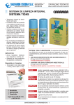
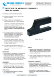
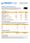
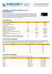
DETECTOR DE FUGAS
MANUAL DEL USUARIO
®
SALVADOR ESCODA S.A.
www.salvadorescoda.com
Provença, 392 pl. 1 y 2
08025 BARCELONA
Tel. 93 446 27 80
Fax 93 456 90 32
CATÁLOGO TÉCNICO
MANUALES, CATÁLOGOS Y HOJAS TÉCNICAS: EN NUESTRA WEB
Detector de fugas de refrigerante semi-conductor SLD-300
Contenidos:
1. Descripción general . . . . . . . . . . . . . . . . . . . . . . . . . . . . . . . . . . . . . . .
2. Características principales . . . . . . . . . . . . . . . . . . . . . . . . . . . . . . . . . .
3. Colocación y carga de las baterías . . . . . . . . . . . . . . . . . . . . . . . . . . . .
4. Características de funcionamiento . . . . . . . . . . . . . . . . . . . . . . . . . . . .
4.1 Indicador de tensión de la batería . . . . . . . . . . . . . . . . . . . . . . . . . .
4.2 Circuito automático/ Característica de reinicio . . . . . . . . . . . . . . . .
4.3 Ajuste de sensibilidad . . . . . . . . . . . . . . . . . . . . . . . . . . . . . . . . . . .
4.4 Indicador de estado del sensor . . . . . . . . . . . . . . . . . . . . . . . . . . . .
4.5 Alarmas visuales /auditivas – Modo mudo . . . . . . . . . . . . . . . . . . .
5. Funcionamiento. . . . . . . . . . . . . . . . . . . . . . . . . . . . . . . . . . . . . . . . . . .
6. Método de detección . . . . . . . . . . . . . . . . . . . . . . . . . . . . . . . . . . . . . . .
7. Mantenimiento. . . . . . . . . . . . . . . . . . . . . . . . . . . . . . . . . . . . . . . . . . . .
pág. 2
pág. 2
pág. 3
pág. 4
pág. 4
pág. 4
pág. 5
pág. 5
pág. 5
pág. 5
pág. 6
pág. 7
1. DESCRIPCIÓN GENERAL
SLD- 300 ofrece la mayor sensibilidad y la respuesta más rápida de un detector de refrigerante portátil disponible
en el mercado. Se consigue a través del empleo de un sensor semiconductor de alta sensibilidad combinado con
un circuito controlado a través de un microprocesador sofisticado.
Además del rendimiento supremo y ventajas funcionales, ofrece una forma diseñada única para proporcionar
gran facilidad de uso y comodidad.
2. CARACTERÍSTICAS PRINCIPALES
•
•
•
•
•
Tipo de sensor: sensor semi-conductor
Sensibilidad mínima: 2g/año (R134a)
Tiempo de respuesta: <2s
Temperatura ambiental: 0°C – 50°C; humedad: < 80% RH (no condensada)
Aplicación de refrigerante: Responderá a todos los refrigerantes halogenados, incluidos cloro y flúor. Esto
incluye, pero no se limita a:
CFCs
p.ej. R12, R11, R500, R503, etc
HCFCs p.ej. R22, R123, R124, R502, etc.
HFCs
•
•
•
•
•
•
•
•
2
p.ej. R134a, R404a, R410a, R125, etc.
Método display: luz indicadora LED roja y azul
Reinicio una pulsación y sensibilidad ajustable siete niveles
La bomba mecánica responde inmediatamente y extrae de los gases de interferencia
Indicador nivel de batería
Indicación de fallo del sensor
Baterías recargables 3.7 V/Li/2200 mAh
Diseño único
Sensor inoxidable flexible
MANUAL DE USUARIO DETECTOR FUGAS SLD-300
®
SALVADOR ESCODA S.A.
www.salvadorescoda.com
Provença, 392 pl. 1 y 2
08025 BARCELONA
Tel. 93 446 27 80
Fax 93 456 90 32
CATÁLOGO TÉCNICO
MANUALES, CATÁLOGOS Y HOJAS TÉCNICAS: EN NUESTRA WEB
Partes del detector:
1. Tecla de encendido / apagado
2. Tecla de sensibilidad: alta / baja
3. Reinicio
4. Alarma
5. Indicador de tensión batería
6. Indicador visual del tamaño de fuga
7. Sensor
8. Sonda flexible
9. Entrada cargador (hembra)
10. Pack de batería
3. COLOCACIÓN Y CARGA DE LAS BATERÍAS
Extraiga la batería e introdúzcala en el compartimento de baterías del detector, teniendo en cuenta la orientación
correcta (vea Fig. 2).
Aviso: para evitar daños personales, no utilice este
detector de fugas en una atmósfera explosiva o
combustible. El sensor y la sonda miden las condiciones
atmosféricas y
medioambientales. Funciona con
temperaturas altas. El resultado es una mezcla de aire
caliente y gas combustible que puede explotar.
Precaución: para evitar daños en el equipo, cargue las
baterías sólo en temperaturas entre 10°C y 40°C. Cargar
las baterías fuera del rango de esta temperatura puede
causar daños permanentes a la batería.
En modo apagado:
Una vez el pack de baterías se ha instalado, conecte el cargador de batería en una salida en la pared y conecte el
JACK del cargador a la unidad (vea Fig. 3). Cuando esté correctamente conectado, el primer LED indicará el
estado de la carga.
Azul intermitente: batería cargando
Azul permanente: batería cargada por completo
Consejo: si se carga en modo apagado, el detector de fugas no se pone en marcha.
En el estado encendido:
Conecte el cargador, las siete luces azules de indicación LED serán constantes.
Nota: se sugiere cargar baterías cuando el detector esté apagado.
Si las baterías son nuevas o están descargadas totalmente deben cargarse por completo en aproximadamente
seis horas. Una vez el LED indique que la batería está cargada, la unidad está lista para funcionar.
MANUAL DE USUARIO DETECTOR FUGAS SLD-300
3
®
SALVADOR ESCODA S.A.
www.salvadorescoda.com
Provença, 392 pl. 1 y 2
08025 BARCELONA
Tel. 93 446 27 80
Fax 93 456 90 32
CATÁLOGO TÉCNICO
MANUALES, CATÁLOGOS Y HOJAS TÉCNICAS: EN NUESTRA WEB
4. CARACTERÍSTICAS DE FUNCIONAMIENTO:
Esta unidad incluye características de funcionamiento destinadas a aumentar el rendimiento y simplificar la
interfaz del usuario. Vea Fig. 1 para familiarizarse con los indicadores y controles de teclado.
4.1 Indicador de tensión de las baterías
El indicador de tensión de la batería permite al usuario comprobar el nivel de batería en todo momento. El primer
LED en la parte inferior es un indicador de estado de batería “inteligente” y permanecerá encendido siempre que
la unidad esté encendida y haya completado el calentamiento. El LED iluminará en uno de los tres colores para
indicar la batería del nivel de tensión de batería:
Si el LED es azul, las baterías están completamente cargadas
Si el LED es morado, las baterías tienen suficiente tensión para funcionar
Si el LED es rojo, las baterías deben recargarse inmediatamente para evitar un rendimiento con errores o
interrupción del funcionamiento
4.2 Característica de circuito automático o de reinicio
La característica de la unidad Circuito Automático y de reinicio que establece la unidad para ignorar
concentraciones ambientales de refrigerante.
El circuito automático- una vez la unidad se enciende y calienta, ésta se autoajusta automáticamente para
“ignorar” el nivel de refrigerante. Solamente en caso de que el nivel de concentración sea superior a este nivel, la
alarma se disparará.
Nota: Ya que esta característica hace que la unidad no tenga en cuenta el refrigerante en el extremo del
sensor después de completar el calentamiento, la unidad debería encenderse y calentarse con aire frío.
La característica reinicio: el reinicio de la unidad durante el funcionamiento hace una función similar; programa
el circuito para ignorar el nivel de refrigerante. Cada vez que pulsa (y suelta) la tecla de reinicio, la unidad ajusta su
rango para detectar el nivel por encima de la concentración estándar. Al aproximarse a una fuga grande y
pulsando “RESET” cada vez que se indica una detección completa, el usuario puede encontrar el origen de la
fuga. De igual modo, la unidad puede cambiarse a aire fresco y reiniciar para obtener sensibilidad máxima.
Reiniciar la unidad cuando no hay refrigerante (aire fresco) permite detectar cualquier nivel por encima de cero. Si
necesita reiniciar la unidad, pulse la tecla de reinicio. Cada vez que pulse esta tecla, todos los LEDs mostrarán el
color morado durante 3 segundos para confirmar la acción de reinicio.
4.3 Ajuste de sensibilidad
La unidad tiene siete niveles de ajuste de sensibilidad. Cuando encienda la unidad, estará configurada en la
posición de sensibilidad más baja.
Para cambiar el grado de sensibilidad de la unidad, pulse la tecla “Sensitivity” y el LED se iluminará en azul. El
número de LEDs iluminados indicará el nivel de sensibilidad. Por ejemplo, si hay 5 luces LED, representa que la
sensibilidad del detector está ajustada en el quinto nivel. La sensibilidad de siete niveles puede ajustarse a la
circulación en tiempo real.
El sonido de BIP estándar también es una indicación del nivel de sensibilidad:
- en sensibilidad ALTA, la unidad emite BIPS de alta frecuencia y en sensibilidad baja, la unidad emite BIPS de
baja frecuencia.
4
MANUAL DE USUARIO DETECTOR FUGAS SLD-300
®
SALVADOR ESCODA S.A.
www.salvadorescoda.com
Provença, 392 pl. 1 y 2
08025 BARCELONA
Tel. 93 446 27 80
Fax 93 456 90 32
CATÁLOGO TÉCNICO
MANUALES, CATÁLOGOS Y HOJAS TÉCNICAS: EN NUESTRA WEB
4.4 Indicador del estado del sensor
El circuito de la unidad puede diagnosticar automáticamente e indicar el estado del sensor. Siempre que se
encienda la unidad, el circuito automáticamente percibe la condición del sensor y puede detectar defectos en
éste.
La indicación del sensor defectuoso:
Si el circuito detecta que el sensor está defectuoso o no hay sensor, los siete LEDs parpadearán en rojo y azul
alternativamente, y emitirán un BIP de alta frecuencia.
4.5 Alarmas visibles/auditiva- modo mudo
Las unidades disponen de dos características de indicaciones de alarmas primarias (sonido de alarma interno y
siete LEDs visuales rojos). Cuando detecte la fuga, los LEds se iluminarán en rojo. El número de luces de la parte
inferior indican el nivel de fuga.
Puede elegir activar tanto las alarmas visuales como auditivas o utilizar sólo las visuales. Cuando encienda la
unidad, ambas se activan. Si quiere cancelar la alarma auditiva, pulse la tecla de alarma. El altavoz interno
quedará en silencio. La fuga será indicada únicamente por el LED de la pantalla. Pulse la tecla Alarma
nuevamente y se reactivará el altavoz interno.
5.1 Pulse y suelte la tecla ON/OFF para encender la unidad.
5.2 El detector empezará a calentarse. El LED se ilumina en morado, desde abajo. El tiempo de calentamiento es
alrededor de 60 segundos.
5.3 Después del calentamiento, la luz de la parte de abajo estará encendida (indicador de tensión de batería) y
emitirá bips constantes, indicando que la unidad está lista para su uso. El primer LED muestra la tensión de
batería, como se menciona más arriba.
5.4. Ajuste el nivel de sensibilidad según la demanda del usuario, tal y como se describe en la Sección de Ajuste
de Sensibilidad.
5.5 Inicio de la búsqueda de fugas: Mueva el extremo de la sonda hacia la fuga sospechada. El sensor flexible
puede proporcionar acceso a áreas menos accesibles.
NOTA: Si la unidad ya ha prestado servicio antes, compruebe que el extremo de la sonda no está obstruido
con suciedad, grasa, etc.
5.6 Si detecta un refrigerante, la unidad comienza a emitir la alarma (el tono audible será cada vez más rápido y se
encenderá el LED). Cuanta más concentración detectada haya, mayor será la alarma, y se encenderán más
luces LED.
5.7 Si la alarma ocurre antes de encontrar el origen de la fuga, puede usar la tecla Reset, tal y como se describe en
la sección de “Reinicio de características”. La unidad puede reiniciarse tantas veces como sea necesario
encontrar el origen de la fuga. Se recomienda esperar unos diez segundos para detectar la fuga después de
haber pulsado la tecla de reinicio.
MANUAL DE USUARIO DETECTOR FUGAS SLD-300
5
®
SALVADOR ESCODA S.A.
www.salvadorescoda.com
Provença, 392 pl. 1 y 2
08025 BARCELONA
Tel. 93 446 27 80
Fax 93 456 90 32
CATÁLOGO TÉCNICO
MANUALES, CATÁLOGOS Y HOJAS TÉCNICAS: EN NUESTRA WEB
En cuanto al método de detección, vea la Figura 4.
6.1 Examen visual del sistema de refrigeración: Las áreas con manchas aceitosas y sucias, válvulas nodo,
resistencias, conectores o tuberías son las áreas con más probabilidades de fuga.
6.2 Inicio de la detección de fugas en la junta a una velocidad de 1cm/s. La distancia entre el extremo del sensor y
la junta debe ser entre 1 y 3 cm.
6.3 Cuando se dispara una alarma, puede indicar que la fuga está cerca. Compruebe el área alrededor y vea si la
alarma se repite. Si se confirma la fuga, encuentre el origen de la fuga desplazando el detector lentamente.
Además, puede encontrar la fuga apartando el detector de la zona de fuga y reiniciando la unidad, ajustar el
nivel de sensibilidad más bajo y repetir el proceso mencionado. Una vez confirmado, haga una marca
alrededor de la fuga y repita este paso para confirmar la fuga.
6.5 Una fuga en la resistencia del evaporador es más difícil de detectar que otras áreas porque el extremo del
sensor alcanza con dificultad la resistencia del evaporador entero. La mayoría de las resistencias de
evaporador están compuestas de módulos y se instalan en un espacio cerrado con ventilador para
intercambio de calor.
El sistema del ventilador debe encenderse durante 10 segundos, y después apagar el ventilador. Espere 10- 15
minutos al evaporador, después use el detector para detectar la salida del condensado (asegúrese de que el
extremo sensor no esté en contacto con el condensado) o para detectar el aire dentro de la cámara de
evaporación. La mayoría de halógenos son más ligeros que el aire y es probable que se acumulen en el punto más
alto de un espacio cerrado. En caso de fuga en la resistencia del evaporador, la alarma señalará fuga aunque es
difícil reparar un evaporador ubicando con certeza la fuga. En la mayoría de casos, debe sustituirse la resistencia
entera.
6
MANUAL DE USUARIO DETECTOR FUGAS SLD-300
®
SALVADOR ESCODA S.A.
www.salvadorescoda.com
Provença, 392 pl. 1 y 2
08025 BARCELONA
Tel. 93 446 27 80
Fax 93 456 90 32
CATÁLOGO TÉCNICO
MANUALES, CATÁLOGOS Y HOJAS TÉCNICAS: EN NUESTRA WEB
Notas antes de la detección de la fuga:
1) Para detectar fugas en el sistema de refrigeración, el sistema debe tener una presión de funcionamiento
normal, o al menos alcanzar parcialmente un mínimo de 50 PSI. La baja temperatura ambiental (inferior a 59 °F
o 15°C) puede reducir la presión que requiere el sistema y provocar que la fuga tarde más en ser detectada. De
no detectarse ninguna fuga, no significa que no existe fuga de gas. Compruebe la presión antes de llegar a una
conclusión.
2) Las áreas en las que se producen fugas suelen estar cubiertas de contaminantes como el aceite o suciedad del
compresor. Asegúrese de que el extremo del sensor no entre en contacto con estos contaminantes.
3) La función de la unidad es detectar el cambio relativo del refrigerante en el extremo del sensor. Encontrar la
fuente de la fuga necesita ajustar manualmente la sensibilidad y que un técnico reinicie el detector.
4) En áreas en las que la atmósfera está contaminada con refrigerante halógeno, pulse la tecla reinicio para
“ignorar” la fuga en el entorno. Asegúrese de no mover el extremo del sensor lejos del entorno contaminado
mientras reinicia el detector.
5) En áreas con viento, el refrigerante halógeno de fuga puede ser diluido rápidamente o extraído del origen de la
fuga. El técnico puede usar una protección contra el viento para aislar el área de fuga o apagar el ventilador
temporalmente.
6) Para evitar una falsa alarma, evite que el extremo del sensor tenga humedad o algún disolvente. Además, el
tornillo del sensor debe estar firmemente ajustado.
Es importante un mantenimiento adecuado a fin de alargar la vida de servicio del detector y mejorar su
rendimiento.
Aviso: Desconecte la corriente eléctrica antes de extraer la carcasa del sensor.
Mantenga el extremo del sensor limpio: use algodón o aire seco para limpiar el escudo del extremo del sensor
si éste se ha contaminado. En ese caso, remoje el extremo del sensor completamente en alcohol durante unos
minutos y luego use aire comprimido para secar, o séquelo con un trozo de tela.
Nota: No use disolventes como gasolina, aceite mineral, aguarrás, ya que estos solventes pueden crear una capa
fina en el sensor y reducir la sensibilidad del detector y hacer que el detector más lento a la hora de responder a
una fuga.
Ponga el detector y el sensor en un lugar seco y limpio; quite las baterías si no usa el detector durante un largo
periodo de tiempo.
MANUAL DE USUARIO DETECTOR FUGAS SLD-300
7
LEAK DETECTOR
OWNER'S MANUAL
®
SALVADOR ESCODA S.A.
www.salvadorescoda.com
Provença, 392 pl. 1 y 2
08025 BARCELONA
Tel. 93 446 27 80
Fax 93 456 90 32
CATÁLOGO TÉCNICO
MANUALES, CATÁLOGOS Y HOJAS TÉCNICAS: EN NUESTRA WEB
SLD-300 Semi-Conductive Refrigerant Leak Detector
Contents:
1. General Description . . . . . . . . . . . . . . . . . . . . . . . . . . . . . . . . . . . . . . .
2. Main Features . . . . . . . . . . . . . . . . . . . . . . . . . . . . . . . . . . . . . . . . . . . .
3. Installing and Charging Batteries . . . . . . . . . . . . . . . . . . . . . . . . . . . . .
4. operating features . . . . . . . . . . . . . . . . . . . . . . . . . . . . . . . . . . . . . . . . .
4.1 Battery Voltage Indicator . . . . . . . . . . . . . . . . . . . . . . . . . . . . . . . . .
4.2 Automatic circuit / Reset feature . . . . . . . . . . . . . . . . . . . . . . . . . . .
4.3 Sensitivity Adjustment . . . . . . . . . . . . . . . . . . . . . . . . . . . . . . . . . . .
4.4 Sensor Status Indicator . . . . . . . . . . . . . . . . . . . . . . . . . . . . . . . . . .
4.5 Audible / Visual Alarms – Mute Feature . . . . . . . . . . . . . . . . . . . . .
5. Operation. . . . . . . . . . . . . . . . . . . . . . . . . . . . . . . . . . . . . . . . . . . . . . . .
6. Detection method . . . . . . . . . . . . . . . . . . . . . . . . . . . . . . . . . . . . . . . . .
7. Maintenance . . . . . . . . . . . . . . . . . . . . . . . . . . . . . . . . . . . . . . . . . . . . .
page. 8
page. 8
page. 9
page. 10
page. 10
page. 10
page. 11
page. 11
page. 11
page. 11
page. 12
page. 13
1. GENERAL DESCRIPTION
SLD-300 offers the greatest sensitivity and fastest response of any portable refrigerant detector available. This is
achieved through the employment of a high sensitive semi-conductive sensor combined with a sophisticated
microprocessor-controlled circuit. In addition to the supreme performance and functional advantages, it offers an
unique designed shape to provide greater ease of use and comfort.
2. MAIN FEATURES
•
•
•
•
•
•
•
Sensor type: Semi-conductive sensor
Minimum Sensitivity: 2g/yr (R134a)
Response time: <2s
Warm up time: <60s
Ambient Environment:
Temperature: 0°C - 50°C; humidity: <80%RH (non condensing)
Application of refrigerant: It will respond to all halogenated (including Chlorine of Fluorine) refrigerants. This
includes, but is not limited to:
CFCs
HCFCs
HFCs
•
•
•
•
•
•
•
•
e.g.R12,R11,R500,R503 etc.
e.g.R22,R123,R124,R502 etc.
e.g.R134a,R404a,R410a,R125 etc.
Display method: Red and blue LED indicator lights
One-touch reset and seven-level adjustable sensitivity
True mechanical pump provides instant response and fast clearing of interference gases
Battery level indication
Sensor failure indication
3.7V /Li /2200mAh rechargeable batteries
Unique shape design
Flexible stainless probe
SLD-300 LEAK DETECTOR OWNER'S MANUAL
9
®
SALVADOR ESCODA S.A.
www.salvadorescoda.com
Provença, 392 pl. 1 y 2
08025 BARCELONA
Tel. 93 446 27 80
Fax 93 456 90 32
CATÁLOGO TÉCNICO
MANUALES, CATÁLOGOS Y HOJAS TÉCNICAS: EN NUESTRA WEB
Parts diagram:
1. On / Off key
2. Sensitivity high / low key
3. Reset key
4. Alarm key
5. Battery voltage indicator (1st LED)
6. Visual leak size indicators (1st-7th LEDs)
7. Sensor
8. Flexible probe
9. Charger input jack
10. Li-lion Battery pack
3. INSTALLING AND CHARGING BATTERIES
Take out the battery pack and insert it to the detector’s battery compartment, noting the correct orientation.
(see Fig 2)
Warning: to prevent personal injury, do not use this leak
detector in an explosive or combustible atmosphere.
Ambient atmosphere is drawn through the probe and
sensor, which operate at a very high temperature.
The resulting hot mixture of air and combustible gas could
explode.
Caution: to prevent equipment damage, charge batteries
only in temperatures between 10°C and 40°C.
Charging batteries outside this temperature range may
cause permanent damage to the batteries.
Charging batteries
Under the status of power off:
Once the battery pack has been installed, plug the battery charger into a wall outlet and connect the charger jack to
the unit (see Fig 3). When it is correctly connected, the first LED will indicate charging status:
Flashing blue = battery charging
Constant blue = battery fully charged
TIP: if it is charged under the status of power off, the leak detector will not be started.
Under the status of power on:
Plug in the charger, seven blue LED indicator lights will be on one by one in circulation during the process of
charging.
When fully charged, the seven blue LED indicator lights will be constant on.
Note: It is suggested to charge batteries when the detector is turned off.
New or completely discharged batteries will take approximately six hours to be fully charged. When the LED
indicates that the batteries are fully charged, plug off the charger, and the unit is ready for operation
10
SLD-300 LEAK DETECTOR OWNER'S MANUAL
®
SALVADOR ESCODA S.A.
www.salvadorescoda.com
Provença, 392 pl. 1 y 2
08025 BARCELONA
Tel. 93 446 27 80
Fax 93 456 90 32
CATÁLOGO TÉCNICO
MANUALES, CATÁLOGOS Y HOJAS TÉCNICAS: EN NUESTRA WEB
4. OPERATING FEATURES:
This unit includes operating features designed to increase usability and simplify user Interface.
Please refer to Fig 1 to familiarize yourself with the indicators and keypad controls as you proceed through this
section.
4.1 Battery Voltage Indicator:
The Battery Voltage Indicator allows the user to see the battery level at all times.
The first LED from the bottom is an “intelligent” battery status indicator and remains on whenever the unit is
powered on and completes the warm-up. The LED will illuminate in one of three colours to indicate the battery
voltage level:
If the LED is blue, the batteries are fully charged
If the LED is purple, the batteries have enough voltage to operate
If the LED is red, the batteries should be immediately recharged to prevent erratic performance or failure of
detection.
4.2 Automatic Circuit/Reset feature:
The unit features Automatic Circuit and Reset functions that set the unit to ignore ambient concentrations of
refrigerant.
Automatic circuit - Upon initial power-on and completion of the warm-up, the unit automatically sets itself to ignore
the level of refrigerant present at the tip. Only a level, or concentration, greater than this level will cause an alarm.
Note: Since this feature causes the unit to ignore any refrigerant present at the sensor tip after warm-up is
completed, the unit should be powered on and allowed to warm up in fresh air.
Reset feature - Resetting the unit during operation performs a similar function; it programs the circuit to ignore the
level of refrigerant present at the tip. Each time the Reset key is pressed (and released), the unit sets its threshold
for detection to a level above the current concentration being detected. By moving closer to a large leak, and
pressing Reset each time a full detection is indicated, the user can pinpoint the source of the leakage. Similarly, the
unit can be moved to fresh air and reset for maximum sensitivity.
Resetting the unit with no refrigerant present (fresh air) causes any level above zero to be detected. If need to reset
the unit, press the Reset key. Each time the Reset key is pressed, all LEDs briefly show purple for about three
seconds to provide a visual confirmation of the reset action.
4.3 Sensitivity Adjustment
The unit provides seven levels of sensitivity adjustment. When the unit is switched on, it is set to the lowest
sensitivity position.
To change the sensitivity of the unit, press the Sensitivity key, and the LEDs light in blue. The number of lighted LED
will indicate the level of sensitivity. For example, if five LED light, it represents that the sensitivity of detector has
been adjusted to the fifth level. Seven level sensitivity could be real-time adjusted in circulation.
The standard beeping tone is also an indication of sensitivity level:
- In HIGH sensitivity, the unit emits high frequency BEEPING, and in LOW sensitivity the unit emits low frequency
BEEPING.
SLD-300 LEAK DETECTOR OWNER'S MANUAL
11
®
SALVADOR ESCODA S.A.
www.salvadorescoda.com
Provença, 392 pl. 1 y 2
08025 BARCELONA
Tel. 93 446 27 80
Fax 93 456 90 32
CATÁLOGO TÉCNICO
MANUALES, CATÁLOGOS Y HOJAS TÉCNICAS: EN NUESTRA WEB
4.4 Sensor Status Indicator
The unit’s circuit has the ability to automatically diagnose and indicate the sensor’s Status.
Whenever the unit is turned on, the circuit automatically senses the condition of the sensor and can detect a failed
or missing sensor.
Failed Sensor Indication:
If the circuit detects a failed or missing sensor, all seven LED fast flash in red and blue alternatively, and beep a high
frequency alarm together.
4.5 Audible / Visual alarms – Mute feature
The unit features two primary alarm indications – an internal speaker audible alarm and seven red LEDs visual
alarm. When detect the leakage, LEDs will light in red. The number of lighted LEDs from bottom up indicate the
level of leakage.
You may choose to activate both the audible and visual alarms, or use only the visual Alarm. Upon power-on, the
unit will activate both. If you wish to cancel the audible alarm, press the Alarm key, it mutes the internal speaker,
and the leakage will be indicated solely by the LED display Press the Alarm Key again, at any time, to reactivate the
internal speaker.
5.1 Press and release the ON/OFF Key to switch the unit on
5.2 The detector will start the warm-up. The LEDs begin cycling in purple, from the bottom up. The warm-up time is
about 60 seconds.
5.3 After warm-up, the first light from the bottom(battery voltage indicator)will be on and the speak beeps at a
steady rate, indicating that the unit is ready for use. The first LED displays the battery voltage, as mentioned
above.
5.4 Set the sensitivity level according to user’s demand, as described in the Sensitivity Adjustment Section.
5.5 Begin searching for leaks Move the probe tip toward the suspected leak. The flexible probe may be shaped to
provide access to hard-to-reach areas.
NOTE: If the unit has previously been in service, verify the probe tip is not obstructed with dirt, grease, etc.
5.6 If a refrigerant is detected, the unit will begin to alarm – the audible tone will quicken and the LEDs will light.
The larger of the detected concentration, the greater it alarms, and more LEDs will light.
5.7 If an alarm occurs before the leak source is pinpointed, the Reset Key may be used to pinpoint the leak, as
described in the Reset Features section.
The unit may be reset as many times as necessary to pinpoint the leak source. It is suggested to wait for about ten
seconds to detect the leakage after pressing rest key.
12
SLD-300 LEAK DETECTOR OWNER'S MANUAL
®
SALVADOR ESCODA S.A.
www.salvadorescoda.com
Provença, 392 pl. 1 y 2
08025 BARCELONA
Tel. 93 446 27 80
Fax 93 456 90 32
CATÁLOGO TÉCNICO
MANUALES, CATÁLOGOS Y HOJAS TÉCNICAS: EN NUESTRA WEB
6. DETECTION METHOD:
As for the detection method, please see Figure 4
6.1. Visually exam the refrigeration system. The oily and dirty spots, node valves, coils, connectors, or pipelines
are the areas most likely to leak gases.
6.2. Start leak detecting at the joint at a speed of 1cm /s and the distance between sensor tip and the joint should be
1-3 cm.
6.3. When an alarm is triggered, it may indicate that the leakage is close by. Detect around that area again and see
if the alarm is repeatable. If a leak is confirmed, pinpoint the leak source by moving slowly from no-leaking
(no-alarm) area to the leaking area from different directions.
Besides, you could also pinpoint the leakage by moving the detector away from the leaking area and reset the
unit, adjusting the sensitivity lower and repeating the above process.
Once confirmed, mark around the leakage and continue detecting the whole line of the system.
6.4. Additional work may be needed to eliminate possible ambiguity, such as, other contaminants at the spot may
also make the detector work abnormally. Please clean the leaking area with dry cloth and blow clean dry air to
the leaking area and repeat step 3 above to confirm the leak.
6.5. Leak on evaporator coil is more difficult to detect than other areas because it is difficult for sensor tip to access
to the whole evaporator coil. Most evaporator coils are composed of modules and are installed in a closed
space with fan for heat exchange.
The system with the fan should be turned on for 10 seconds and then turn off the fan, wait 10-15 minutes at the
evaporator, then use detector to detect the outlet of the condensate (make sure the sensor tip doesn’t touch with
the condensate),or detect the air inside the evaporator chamber.
Most halogens are lighter than the air and likely to accumulate at the highest spot in the closed space.
An alarm may indicate a leak at the evaporator coil, but it is hard to repair evaporator by pinpointing the precise leak
location. In most cases, the whole coil has to be replaced.
SLD-300 LEAK DETECTOR OWNER'S MANUAL
13
®
SALVADOR ESCODA S.A.
www.salvadorescoda.com
Provença, 392 pl. 1 y 2
08025 BARCELONA
Tel. 93 446 27 80
Fax 93 456 90 32
CATÁLOGO TÉCNICO
MANUALES, CATÁLOGOS Y HOJAS TÉCNICAS: EN NUESTRA WEB
NOTES BEFORE LEAKAGE DETECTION:
1) In order to detect leakage in a refrigeration system, the system must have normal operating pressure, or at least
partially reaches to minimum 50 PSI. Low environmental temperature (lower than 59 or 15°C) may lower the
system required pressure and may make the leakage less likely to be detected. No leak detected does not
mean the system does not have gas leakage. Check the pressure before making the conclusion.
2) Leaking areas are usually covered with contaminants such as compressor oil or dirt, be careful not to make the
sensor tip contact with these contaminants.
3) The function of the detector is to detect refrigerant’s relative change at the sensor tip.
Pinpointing the leakage source needs to manually adjust the sensitivity and reset the detector by the
technician.
4) In areas where the atmosphere is contaminated with halogen refrigerant, press reset key to ignore the leakage
in the background.
Make sure not move the sensor tip away from the contaminated background while resetting the detector.
5) In windy area, the leaking halogen refrigerant may be quickly diluted or removed from the leakage source.
The technician may use a wind shield to isolate the leak area or temporarily turn off the fan.
6) To avoid false alarm, prevent the sensor tip against any moisture or other solvent. Besides, the screw of the
sensor should be tightened up.
Proper maintenance is important and may extend the service life and improve the performance of your detector.
Warning: Turn the power off before clearing the shell of sensor.
Keep the sensor tip clean: Use cotton cloth or dry air to clean the shield on the sensor tip if it gets contaminated. If
the sensor tip itself is contaminated, soak the tip in absolute alcohol for a few minutes, and then use compressed
air to blow it dry, or dry it with cloth.
Note: Never use strong solvents such as Gasoline, mineral oil, turpentine, these solvents may coat the sensor with
a thin film and reduce the sensitivity of the detector and make the detector slow to respond to a leak.
Put the detector and the sensor in a dry and clean place; remove the batteries if the detector is not used for a long
time.
14
SLD-300 LEAK DETECTOR OWNER'S MANUAL