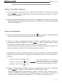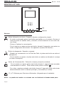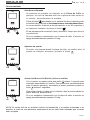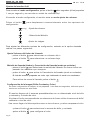
1
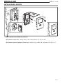
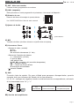
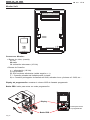
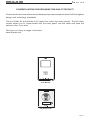
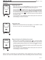
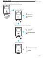
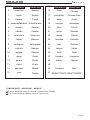
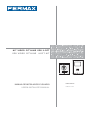
KIT VIDEO CITYLINE VDS iLOFT VDS VIDEO CITYLINE iLOFT KIT MANUAL DE INSTALADOR Y USUARIO USER& INSTALLER’S MANUAL E S PA Ñ O L ENGLISH VDS VDS iLoft iLoft Kit Kit Pag 2 VDS VDS iLoft iLoft Kit Kit ¡ENHORABUENA POR DISPONER DE UN PRODUCTO DE CALIDAD! Fermax electrónica desarrolla y fabrica equipos de prestigio que cumplen los más altos estándares de diseño y tecnología. El Kit video iLoft, incluye el monitor de videoportero iLoft, manos libres y con patalla a todo color que le permitirá comunicarse con la placa de calle, ver la persona que le está llamando y abrirle la puerta de entrada si así lo desea. Esperamos disfrute de sus funcionalidades. www.fermax.com Monitor iLoft Placa de calle City Pag 3 VDS VDS iLoft iLoft Kit Kit «Kit Video Cityline iLOFT» Este documento técnico lo edita FERMAX ELECTRONICA S.A.E. con carácter informativo, y se reserva el derecho a modificar características de los productos que en él se refieren en cualquier momento y sin previo aviso. Estos cambios vendrán reflejados en posteriores ediciones del mismo. Cod. 97411EIc V06_11 Pag 4 ESPAÑOL VDS VDS iLoft iLoft Kit Kit INDICE SECCION I - MANUAL DEL INSTALADOR .................................................................. 7 Instalación: Alimentador ...................................................................................................... 8 Placa de calle .................................................................................................. 8 Monitor .............................................................................................................. 9 Descripción y ajustes de los equipos: Placa de calle .................................................................................................. 10 Monitor iLoft ...................................................................................................... 12 Características Técnicas de los equipos ........................................................ 13 Esquema de cableado ......................................................................................... 14 Ampliaciones ........................................................................................................ 15 Programación de los equipos: Monitor iLoft.Programación ADS .................................................................... 16 SECCION II - MANUAL DE USUARIO ......................................................................... 19 Monitor iLoft .......................................................................................................... 20 Controles .......................................................................................................... 20 Funcionamiento ............................................................................................... 21 Ajustes del monitor ......................................................................................... 22 Pag 5 VDS VDS iLoft iLoft Kit Kit Pag 6 VDS VDS iLoft iLoft Kit Kit Sección I - Manual del Instalador Pag 7 VDS VDS iLoft iLoft Kit Kit INSTALACIÓN DEL ALIMENTADOR Instalación en carril DIN Montaje Fijación con tornillos Desmontaje MA DE 50-6 0 Hz. +1 IN SP AIN 50V A MA 8V 12 V X. 1. 5A 1A FU EN TE A KIT LIME DIG NTAC ITA ION L INSTALACIÓN PLACA DE CALLE 1 2 1 5.5.70m 7f ee t A MARI A LORC 3 Pag 8 4 VDS VDS iLoft iLoft Kit Kit INSTALACIÓN DEL MONITOR 0m t 1.6 fee 5 2 . 5 (*) F2 0m t 1.6 fee 5 5.2 F1 T A+ Ct - L + M V V (*) M (*) Quitar la etiqueta electrostática de protección. Dimensiones monitor (Alto x Ancho x Prof .): 197 x 131 x 60 mm / 7,7” x 5,1” x 2,3” Dimensiones caja de empotrar de Fermax (Alto x Ancho x Prof.): 158 x 108 x 45 mm / 6,2” x 4,2” x 1,7” Pag 9 VDS VDS iLoft iLoft Kit Kit DESCRIPCIÓN DE LOS EQUIPOS Placa de calle G) H) JP4 CN2 MASTER SLAVE LEDS ON LEDS OFF CT OUT CT IN CN1 PACK EXTENSION SW1 PROG PAN & TILT 10 DL2 SW1 DL2 CN2 TARJETERO TAG HOLDER E) + AUDIO IDIOMA LANGUAGE EXIT 18V DC CN3 STATUS A B C D E ON A) B) C) D) JP2 JP3 JP4 MIC VDS CN1 JP2 JP3 I) AMPLIFICADOR - VERSTÄRKER AMPLIFICATEUR - AMPLIFIER J) CAM - L V M +12 C NO NC BS - S CT K) L) CN3 ALIMENTACION F) C POWER SUPPLY - + 18 Vdc CN7 NO VERSION : M) NC MONITOR TEST A) Puentes de configuración: JP2 : Selección Placa Principal / Placa Secundaria. Configuración por defecto: Placa Principal Placa Principal Placa Secundaria Leds ON Leds OFF JP3 : Leds iluminación cámara JP4 : Activación cámara/salida auxiliar CT: salida 11 Vdc CT: entrada Conectar 12 Vdc para activar permanentemente cámara + leds B) CN1: Conexión módulo de extensión de llamadas o hasta 3 pulsadores. C) CN2: Conexión iluminación tarjeteros y pulsadores. L+ / L-: Luz tarjetero o pulsador. CP: Común de pulsadores. D) DL2: Led de diagnóstico. Si existe un cortocircuito entre + y L, al llamar desde placa emite una serie de destellos cortos. E) Enfoque de telecámara: 10º Pan&Tilt (±10º) 10º 10º Pag 10 10º VDS VDS iLoft iLoft Kit Kit F) CN7: Video test monitor Conector de test y programación de monitores G) SW1 (mapeado) Botón para entrar en modo programación de pulsadores. «Ver manual de Mapaedo» H) Síntesis de voz: Ver CODIFICACIÓN al final de este manual. A B C D E ON Selección del idioma del mensaje de «puerta abierta». I) Ajustes de Audio: “puerta abierta” J) MIC Conexión micrófono (micrófono ubicado en el perfil inferior de la placa). K) Conectores Placa: • Bornas de video, (coaxial). V: vivo M: malla Ct: activación telecamara (11 Vdc) • Bornas de Conexión del sistema: +, -: alimentación (18 Vdc). L: bus de datos. +12: salida12 Vdc C, NO, NC: contactos relé (conexión abrepuertas) BS, -: pulsador zaguán. SP, - : sensor de puerta abierta. S: activación del cambiador • : conexión Pulsador. L) CN3: Conexión leds de estado. De gran utilidad para personas discapacitadas, permite conectar leds que informan del estado de la comunicación. L2, L3, L4: entregan un negativo cuando se realiza la acción correspondiente, activando el led conectado entre “Lx” y “+”: + L1 L2 L3 L4 L4 L2 L3 L4 Led de llamada Led de comunicación Led apertura de puerta M) Versión del amplificador. Pag 11 VDS VDS iLoft iLoft Kit Kit Monitor iLoft F2 F1 T A+ Ct - L + M V V M F2 F1 T A+ Ct - L + V V M Conectores Monitor: • Bornas de video, (coaxial). V: vivo M: malla Ct: activación telecamara (10 Vdc) • Bornas de Conexión: +, -: alimentación (18 Vdc). L: bus de datos. F1, F2: funciones adicionales (salida negativo «-»). T, -: Conexión pulsador de llamada puerta vivienda A, +: Conexión prolongador de llamada ref.2040, activador luces y timbres ref. 2438, etc... Display de programación: muestra el número ADS de llamada programado. Botón PRG: botón para entrar en modo programación. Display PR PR OG OG PROG. . KON . SW1 Botón PRG Pag 12 SW2 SW3 SW4 SW5 Pulsar para entrar en programación VDS VDS iLoft iLoft Kit Kit CARACTERÍSTICAS TÉCNICAS Alimentación 18 Vdc Consumo IP43 57 mA 180 mA 390 mA [-10 , +60 °C] en reposo video activo audio y video activo Temperatura de funcionamiento [14, 140ºF] 1W Potencia audio sentido vivienda-calle 0,15 W Potencia audio sentido calle-vivienda Volumen regulable en ambos sentidos 18 Vdc Alimentación Consumo en reposo en llamada con video con audio y video 15 mA 300 mA 250 mA 400 mA [5 , +40 °C] [41, +104 ºF] [0 - 90%] Temperatura de funcionamiento Humedad TFT Pantalla Plana . 4" Diagonal - Resolución: Horizontal: 480 Line TV - Vertical: 234 Line TV Señal de video: Señal compuesta 1 Vpp 75 Ω, 7 Mhz Dimensiones monitor (Alto x Ancho x Prof.): 197 x 131 x 60 mm / 7,7” x 5,1” x 2,3” Pag 13 VDS VDS iLoft iLoft Kit Kit ESQUEMA DE CABLEADO (*) IMPORTANTE F2 F1 T A Ct - L + M V V M 10 Kohm Colocar una resistencia de 10 Kohms entre los bornes + y L del último monitor. 75 Ohm P1 + L P1: Pulsador de llamada puerta vivienda. D. max. MADE IN SPAIN 50-60 Hz. +1 50VA 8V 12 V MAX. 1. 5A 1A FUENT E ALIME KIT DIGITNTACIO AL N 30 m Vac 18 Vdc + -+ - ~ 240V ~ 18Vdc+12Vac ON OVERLOAD D COAX OUTPUT 18 V ; 1.5 S 12 V ; 12 Vac ~ ~ L 12 Vac - + metros / metres pies / feet 2 mm AWG 1 - 50 3 - 150 1 mm 2 17 75 Ohm 50 - 100 150 - 300 1,5 mm 2 15 75 Ohm 100 - 200 300 - 600 2,5 mm 2 13 75 Ohm JP4 CN2 MASTER SLAVE LEDS ON LEDS OFF CT OUT CT IN CN1 PACK EXTENSION SW1 PROG PAN & TILT 10 DL2 SW1 DL2 CN2 TARJETERO TAG HOLDER AUDIO IDIOMA LANGUAGE EXIT 18V DC + A B C D E ON JP2 JP3 JP4 CN3 STATUS AMPLIFICADOR - VERSTÄRKER AMPLIFICATEUR - AMPLIFIER VDS CN1 JP2 JP3 MIC INPUT 100-240 V ; 1,2A 50-60 Hz CAM - L V M +12 C NO NC BS - S CT CN3 ALIMENTACION C POWER SUPPLY - + 18 Vdc 12 Vac Pag 14 CN7 MONITOR TEST NO NC VERSION : VDS VDS iLoft iLoft Kit Kit AMPLIACIONES Este Kit puede ser ampliado con dos teléfonos o un monitor adicional sin necesidad de fuentes de alimentación extra. Conexión Monitor adicional 10 KOhm F2 F1 T A Ct - L + M V V M F2 F1 T A Ct - L + M V V M 75 Ohm L - + COAX Alimentador 18Vdc Conexión teléfonos adicionales 10 KOhm F1F2 + - L +A T SW1 F2 F1 T A Ct - L + M V V M F1F2 + - L +A T L - + SW1 L - + 75 Ohm - L + COAX Alimentador 18Vdc Pag 15 VDS VDS iLoft iLoft Kit Kit PROGRAMACIÓN DEL MONITOR iLOFT Opción 1: Desde Placa + Monitor 2 1 PR OG . PR OG . PR OG . 2 seg. 2 seg. < 2 min Opción 2: Desde Monitor 1 2 número actual PR (2 seg.) PR OG . OG 3 . 4 PROG. PROG. KON (2 seg.) KON SW1 SW1 (SW2) Pag 16 SW2 SW3 (SW3) SW4 SW2 SW3 SW4 SW5 SW5 (SW4) número OK número actual y CORRECTO número NO OK número NO CORRECTO (Err) VDS VDS iLoft iLoft Kit Kit ¡El monitor no funcionará mientras no haya sido programado! Opción 1: desde Placa + Monitor 1º. Con el monitor conectado pulse el botón de programación durante 2 segundos «PROG » (para acceder a éste es necesario levantar la tapa frontal). Se oirá un sonido de confirmación. 2º. Pulse el botón de llamada a vivienda. De nuevo se produce confirmación con otro tono de llamada diferente, además de visualizar en el DISPLAY el número programado (durante 2 segundos). Opción 2: Desde Monitor 1º. Entrar en modo configuración: Pulsar el botón dos segundos. El led parpadea 1 vez por segundo y se escucha un sonido de confirmación. 2º. Poner el monitor en programación: Con el monitor conectado pulsar el botón de » (para acceder a éste es neceprogramación durante 1 segundo « PROG sario levantar la tapa frontal). Se oirá un sonido de confirmación. En ese momento, lo primero que hace el monitor es indicar mediante el DISPLAY el número del monitor actual. Si no está programado mostrará: - - - 3º. Programar el número de llamada: Cada vez que se presiona el botón correspondiente a centenas, decenas o unidades se incrementa una cifra y se visualiza en el DISPLAY. Centenas: Pulsar el botón (SW2) Decenas: Pulsar el botón (SW3) Unidades: Pulsar el botón (SW4) Una vez se llega al 9 y se vuelve a presionar continúa con el 0 y emite un tono grave de error.La siguiente pulsación comienza desde el número 1. 4º. Salir de programación: Pulsar el botón de programación durante 2 segundos «PROG » o esperar 30 segundos sin pulsar ningún botón. Al salir de programación se almacena el número indicado. Si es correcto (entre 1 y 199) se escucha un sonido de confirmación, si no es correcto se escucha un sonido de error, además de visualizarse en el DISPLAY el mensaje «Err». Pag 17 VDS VDS iLoft iLoft Kit Kit Pag 18 VDS VDS iLoft iLoft Kit Kit Sección II - Manual del Usuario Enhorabuena por disponer de un producto de calidad! El monitor de videoportero iLoft, manos libres y con patalla a todo color que le permitirá comunicarse con la placa de calle, ver la persona que le está llamando y abrirle la puerta de entrada si así lo desea. Esperamos disfrute de sus funcionalidades. www.fermax.com Pag 19 VDS VDS iLoft iLoft Kit Kit MONITOR iLOFT ADS Led Botones Botones Botón Activación de Audio, Colgado y Ajustes configuración (menú). · Al recibir una llamada pulsar este botón para hablar con el visitante. Se abre el canal de audio en sentido calle y vivienda, el funcionamiento es en modo manos libres. · Pulsar al finalizar la comunicación. · Con el monitor en reposo pulsar este botón, durante 2 segundos, para entrar en modo configuración del monitor. Ver apartado «Ajustes del Monitor». Botón de abrepuertas / llamada a conserje. · Estando en conversación con la Placa de Calle, al pulsar este botón se activa el abrepuertas. · Con el monitor en reposo, al pulsar este botón se realiza una llamada al conserje (si existe conserjería). Botón de Autoencendido / Selección cámara principal-secundaria. · Con el monitor en reposo pulsar este botón durante 1 segundo para encender manualmente el monitor. Para activar audio pulsar el botón . · Con video, mantener pulsado este botón durante 2 segundos para seleccionar secuencialmente entre la camara principal y secundaria (si existe). F1 y F2: Botones para Funciones Adicionales. (Asignadas por el instalador). NOTA: La pantalla del monitor se enciende una vez finalizada la llamada desde placa. Pag 20 VDS VDS iLoft iLoft Kit Kit Funcionamiento Atender una llamada Al presionar el pulsador de llamada, en la Placa de Calle se produce un tono de llamada tanto en la placa de calle como en el monitor, encendiéndose la pantalla. Pulsar el botón para hablar con el visitante Se abre el canal de audio en sentido calle y vivienda, el funcionamiento es en modo manos libres. La comunicación finalizará automáticamente a los 90 segundos o en cualquier momento al pulsar el botón . El led permanecerá encendido (azul) durante el tiempo que dure la conversación. Si no se establece comunicación con la placa de calle, el monitor se apaga automáticamente pasados 30 seg. Apertura de puerta Al recibir una llamada desde la placa de calle, es posible abrir la puerta en cualquier momento, pulsado el botón Activación Manual del Monitor (Autoencendido) Con el monitor en reposo pulsar este botón durante 1 segundo para encender manualmente el monitor. Para seleccionar secuencialmente entre la camara principal y secundaria (si existe) mantener pulsado el botón durante 2 segundos. Para activar el audio y hablar con el visitante o abrir la puerta realizar los pasos descritos anteriormente. Si no se establece comunicación con la placa de calle, el monitor se apaga automáticamente pasados 30 seg. NOTA: Si existe más de un monitor iLoft en la instalación y se realiza la llamada a un monitor, el resto de los monitores mostrarán el led en color azul avisando que el canal está ocupado. Pag 21 VDS VDS iLoft iLoft Kit Kit Ajustes del monitor iLoft dos segundos (el led parpadea Para acceder al modo configuración, pulsar el botón 1 vez por segundo y se escucha un sonido de confirmación). Al acceder al modo configuración, el monitor entra en modo ajuste de volumen. Pulsar el botón configuración: para desplazarse secuencialmente entre las opciones de (2 seg.) : Ajuste de volumen. : Selecciónde Melodía. :Ajuste de imágen. Para ajustar las diferentes opcines de configuración, estando en la opción deseada realizar los pasos siguientes: Ajuste Volumen del timbre de Llamada para seleccionar un volumen alto o - pulsar el botón - pulsar el botón para seleccionar un volumen bajo. Melodía de llamada (timbre) y Cancelación de llamada (modo no molestar) - pulsar el botón para seleccionar la melodía de llamada. De forma cíclica van pasando las melodías que incorpora. - pulsar el botón para activar la Cancelación de llamada (modo no molestar); El led del monitor parpadea en color rojo indicando el modo «no molestar» Para activar de nuevo la llamada, pulsar el botón . Configuración de la Imagen (Brillo-Contraste y Color) En modo configuración de imagen, el led parpadea 1 vez cada dos segundos, indicando que el monitor se encuentra en este modo. El monitor dispone de 4 escenas preestablecidas con un determinado nivel de brillo y contraste y 4 niveles de color. Al pulsar el botón correspondiente se selecciona de forma cíclica la escena de brillo/ contraste o nivel de color. Una vez se llega a la última opción suena un tono de error y vuelve a empezar el ciclo. Pag 22 - pulsar el botón para seleccionar la escena de brillo y contraste. - pulsar el botón para configurar el color. VDS VDS iLoft iLoft Kit Kit Ajustes del monitor iLoft - Guía rápida Ajuste Volumen de llamada (2 seg.) Volumen ALTO Volumen BAJO Entrar en modo configuración Selección de Melodía y cancelación llamada Selección de MELODÍA DE LLAMADA CANCELACION LLAMADA Configuración de la imagen BRILLO-CONTRASTE COLOR Pag 23 VDS VDS iLoft iLoft Kit Kit CONGRATULATIONS ON PURCHASING THIS QUALITY PRODUCT! Fermax electronics manufactures and develops top class equipment which fulfil the highest design and technology standards. The iLoft Video Kit includes the iLoft, hands free, video door entry monitor. The full colour screen allows you to communicate with the entry panel, see the caller and open the entrance door if you wish. We hope you enjoy its range of functions. www.fermax.com iLoft Monitor City Entry Panel Page 1 VDS VDS iLoft iLoft Kit Kit This technical document of an informative nature is published by FERMAX ELECTRONICA S.A.E., which reserves the right to modify characteristics of the products referred to herein at any time and without prior notice. These changes will be reflected in subsequent editions of this document. Cod. 97411EIc V06_11 Page 2 ENGLISH VDS VDS iLoft iLoft Kit Kit TABLE OF CONTENTS SECTION I - INSTALLATION MANUAL ....................................................................... 5 Installation Power Supply ................................................................................................... 6 Entry Panel ....................................................................................................... 6 Monitor .............................................................................................................. 7 Equipment Descriptions and Settings Entry Panel ....................................................................................................... 8 iLoft Monitor ...................................................................................................... 10 Technical Features of the Equipment .............................................................. 11 Wiring Diagram ..................................................................................................... 12 Extensions ............................................................................................................. 13 Equipment Programming: iLoft Monitor. ADS Programming .................................................................... 14 SECTION II - USER MANUAL ..................................................................................... 17 iLoft Monitor .......................................................................................................... 18 Controls ............................................................................................................ 18 Operation .......................................................................................................... 19 Monitor Settings ............................................................................................... 20 Page 3 VDS VDS iLoft iLoft Kit Kit Page 4 VDS VDS iLoft iLoft Kit Kit Section I - Installer Manual Page 5 VDS VDS iLoft iLoft Kit Kit POWER SUPPLY INSTALLATION DIN rail Installation Assembly Fixing with screws Disassembly MA DE 50-6 0 Hz. +1 IN SP AIN 50V A MA 8V 12 V X. 1. 5A 1A FU EN TE A KIT LIME DIG NTAC ITA ION L OUTDOOR PANEL INSTALLATION 1 2 1 5.5.70m 7f ee t A MARI A LORC 3 Page 6 4 VDS VDS iLoft iLoft Kit Kit MONITOR INSTALLATION 0m t 1.6 fee 5 2 . 5 (*) F2 0m t 1.6 fee 5 5.2 F1 T A+ Ct - L + M V V (*) M (*) Remove electrostatic protective tag. Dimensions of monitor (Height x Width x Depth.): : 197 x 131 x 60 mm / 7,7” x 5,1” x 2,3” Dimensions of Fermax box (Height x Width x Depth): 158 x 108 x 45 mm / 6,2” x 4,2” x 1,7” Page 7 VDS VDS iLoft iLoft Kit Kit DESCRIPTION OF EQUIPMENT Outdoor panel G) H) JP4 CN2 MASTER SLAVE LEDS ON LEDS OFF CT OUT CT IN CN1 PACK EXTENSION SW1 PROG PAN & TILT 10 DL2 SW1 DL2 CN2 TARJETERO TAG HOLDER E) + AUDIO IDIOMA LANGUAGE EXIT 18V DC CN3 STATUS A B C D E ON A) B) C) D) JP2 JP3 JP4 MIC VDS CN1 JP2 JP3 I) AMPLIFICADOR - VERSTÄRKER AMPLIFICATEUR - AMPLIFIER J) CAM - L V M +12 C NO NC BS - S CT K) L) CN3 ALIMENTACION F) C POWER SUPPLY - + 18 Vdc CN7 NO VERSION : M) NC MONITOR TEST A) Configuration Switches: JP2 : Main Panel/Secondary Panel Selection. Default Configuration: Main Panel JP3 : Leds iluminación cámara JP4 : Camera activation/auxiliary output Main Panel Secondary Panel Leds ON Leds OFF CT: 11 Vdc output Connect 12 Vdc to permanetly CT: input activate camera + leds B) CN1: Connection call extension module or up to 3 buttons. C) CN2: Connection cardholder and button lighting. L+ / L-: Cardholder Backlight. CP: Common button wire. D) DL2: Diagnostic Led. If there is a short circuit between + y L, when a call is made from the panel, it emits a series of short flashes. E) Focus the camera: 10º Pan&Tilt (±10º) 10º 10º Page 8 10º VDS VDS iLoft iLoft Kit Kit F) CN7: Video test monitor Test and monitor programming connector G) SW1 (mapping) Button to enter button programming mode. See manual «Mapping». H) Síntesis de voz: See CODIFICATION at the endo of this manual. A B C D E ON Select language for «open door» message. I) Audio Settings:: “open door” J) MIC Microphone connection (microphone located in the lower panel profile). K) Panel Connectors: • Video terminals (coaxial): V: live M: shield Ct: camera activation (10 Vdc) • System connection terminals: +, -: power supply (18 Vdc). +12: 12 Vdc output. L: data bus. C, NA, NC: relay contacts (dooropener connection) BS, -: entrance hall button. SP, - : door-open sensor. S: activation of the exchanger • : Button Connection (prewired in factory). L) CN3: CN3: Connection Status Leds Very useful for disabled people, allowing leds to be connected which provide information on communication status. L2, L3, L4: generates a negative signal when the corresponding action is taken, activating the led connected between “Lx” and “+”: + L1 L2 L3 L4 L4 L2 L3 L4 Call Led Communication Led Lock Release Led M) Amplifier version. Page 9 VDS VDS iLoft iLoft Kit Kit iLoft Monitor F2 F1 T A+ Ct - L + M V V M F2 F1 T A+ Ct - L + V V M Monitor Conectors: • Video terminals (coaxial): V: live M: shield Ct: camera activation (10 Vdc) • Connection Terminals: +, -: 18 Vdc power supply). L: data bus. F1, F2: additional functions (negative output «-»). T, -: Call Button Connection for Door of Residence A, +: Call extension connection ref. 2040, light and bell activator ref. 2438, etc... Programming display: shows the ADS call number programmed. PRG button: button to go into programming mode. Display PR PR OG OG . . PROG. KON SW1 PRG button Page 10 SW2 SW3 SW4 SW5 Press to go into programming mode VDS VDS iLoft iLoft Kit Kit TECHNICAL FEATURES Power Supply 18 Vdc Consumption 57 mA 180 mA 390 mA [-10 , +60 °C] on standby with video with audio and video IP43 Operating temperature [14, 140ºF] 1W Audio power from the apartment to the panel 0,15 W Audio power from the panel to the apartment Adjustable volume both ways 18 Vdc Power Supply Consumption on standby making a call with video with audio and video Operating temperature Humidity TFT Flat Screen. 4" Diagonal - Resolution: Horizontal: 480 Line TV - Vertical: 234 Line TV Video signal: 15 mA 300 mA 250 mA 400 mA [5 , +40 °C] [41, +104 ºF] [0 - 90%] Compound signal 1 Vpp 75 Ω, 7 Mhz Dimensions of monitor (Height x Width x Depth): 197 x 131 x 60 mm / 7,7” x 5,1” x 2,3” Page 11 VDS VDS iLoft iLoft Kit Kit WIRING DIAGRAM (*) IMPORTANT F2 F1 T A Ct - L + M V V M 10 Kohm Set up a 10Kohms resistance between the + and L terminals on the last monitor. 75 Ohm P1 + L P1: Call pushbutton at the apartment’s door. D. max. MADE IN SPAIN 50-60 Hz. +1 50VA 8V 12 V MAX. 1. 5A 1A FUENT E ALIME KIT DIGITNTACIO AL N 30 m Vac 18 Vdc + -+ - ~ 240V ~ 18Vdc+12Vac ON OVERLOAD D COAX OUTPUT 18 V ; 1.5 S 12 V ; 12 Vac ~ ~ L 12 Vac - + metros / metres pies / feet 2 mm AWG 1 - 50 3 - 150 1 mm 2 17 75 Ohm 50 - 100 150 - 300 1,5 mm 2 15 75 Ohm 100 - 200 300 - 600 2,5 mm 2 13 75 Ohm JP4 CN2 MASTER SLAVE LEDS ON LEDS OFF CT OUT CT IN CN1 PACK EXTENSION SW1 PROG PAN & TILT 10 DL2 SW1 DL2 CN2 TARJETERO TAG HOLDER AUDIO IDIOMA LANGUAGE EXIT 18V DC + A B C D E ON JP2 JP3 JP4 CN3 STATUS AMPLIFICADOR - VERSTÄRKER AMPLIFICATEUR - AMPLIFIER VDS CN1 JP2 JP3 MIC INPUT 100-240 V ; 1,2A 50-60 Hz CAM - L V M +12 C NO NC BS - S CT CN3 ALIMENTACION C POWER SUPPLY - + 18 Vdc 12 Vac Page 12 CN7 MONITOR TEST NO NC VERSION : VDS VDS iLoft iLoft Kit Kit EXTENSIONS This Kit can be extended with two telephones or an additional monitor without the need for extra power supplies. Additional Monitor Connection 10 KOhm F2 F1 T A Ct - L + M V V M F2 F1 T A Ct - L + M V V M 75 Ohm - L + COAX Power Supply 18Vdc Additional Telephone Connection 10 KOhm F1F2 + - L +A T SW1 F2 F1 T A Ct - L + M V V M F1F2 + - L +A T L - + SW1 L - + 75 Ohm L + COAX Power Supply 18Vdc Page 13 VDS VDS iLoft iLoft Kit Kit PROGRAMMING THE iLOFT MONITOR Option 1: From Panel + Monitor 2 1 PR PR OG PR OG . . OG . 2 seg. 2 sec. < 2 min Option 2: From the Monitor 1 2 current number PR (2 sec.) PR 3 OG OG . . 4 PROG. PROG. KON (2 sec.) KON SW1 SW1 (SW2) Page 14 SW2 SW3 SW4 (SW3) SW2 SW3 SW4 SW5 SW5 (SW4) number OK current number and CORRECT number NOT OK number NOT CORRECT (Err) VDS VDS iLoft iLoft Kit Kit The monitor will not function until it has been programmed! Option 1: From Panel + Monitor » for 2 1. With the monitor connected, press the programming button «PROG seconds (to access this, you must lift up the front cover). A confirmation tone will be emitted. 2. Press the call-to-residence button. A different confirmation tone will once again sound, and the programmed number will be shown on the DISPLAY (for 2 seconds). Option 2: From the Monitor 1. Go into configuration mode: Press the button for two seconds. The LED blinks once each second and a confirmation tone is emitted. 2. Put the monitor into programming mode: With the monitor connected, press the » for 1 second (to access this, you must lift up programming button «PROG the front cover). A confirmation tone will be emitted. The first thing the monitor then does is indicate the number of the current monitor on the DISPLAY. If it is not programmed, it will show the following: - - - 3. Programme the call number: Each time the button corresponding to hundredths, tenths or units is pressed, the figure goes up by one and is shown on the DISPLAY. Hundredths: Press the button (SW2) Tenths: Press the button (SW3) Units: Press the button (SW4) Once you reach 9, if you press again, it returns to 0 and a low error tone is emitted. The next time you press, it will go to 1. 4. Exit programming mode: Press the programming button « PROG » for 2 seconds, or wait 30 seconds before pressing any button. When you exit programming mode, the number indicated is stored. If it is correct (between 1 and 199), a confirmation tone is emitted; if it is not correct, an error tone is emitted, and the «Err» message is shown on the DISPLAY. Page 15 VDS VDS iLoft iLoft Kit Kit Page 16 VDS VDS iLoft iLoft Kit Kit Section II - User Manual Congratulations on purchasing this quality product! The iLoft Video Door Entry System includes the iLoft Monitor. The full colour screen allows you to communicate with the entry panel, see the caller and open the entrance door if you wish. We hope you enjoy its range of functions. www.fermax.com Page 17 VDS VDS iLoft iLoft Kit Kit ADS iLOFT MONITOR Led Buttons Buttons Audio Activation, Hanging-up and Configuration-adjustment Button (menu). · When a call is received, press this button to speak to the visitor. The audio channel between the street and the home is opened; operation is in hands-free mode. · Press to end the communication. · With the monitor on standby, press this button for 2 second to go into monitor configuration mode. See the «Monitor Settings» section. Door-opener / call to reception button. · When you are in conversation with the Street Panel, pressing this button will activate the door-opener. · With the monitor on standby, when you press this button a call will be made to reception (if there is one). Auto-start / Main-Secondary Camera Selection Button. · With the monitor on standby, press this button for 1 second to switch the monitor on manually. To activate the audio, press the button . · With video, hold this button down for 2 seconds to sequentially select between the main camera and the secondary camera (if there is one). F1 and F2: Buttons for Additional Functions (assigned by the installer). NOTE: The monitor screen goes on once the call from the panel has ended. Page 18 VDS VDS iLoft iLoft Kit Kit Operation Answering a call When the call button on the Street Panel is pressed a call tone is emitted both at the panel and on the monitor, and the screen goes on. Press the button to speak with the visitor. The audio channel between the street and the home will be opened; operation is in hands-free mode. The communication will automatically end after 90 seconds, or at any time by pressing the button . The LED will remain on (blue) while the conversation lasts. If communication is not established with the street panel, the monitor will automatically go off after 30 seconds. Opening the door When a call is received from the street panel, it is possible to open the door at any time, by pressing the button Manual Activation of the Monitor (Auto-start) With the monitor on standby, press this button for 1 second to switch the monitor on manually. To sequentially select between the main camera and the secondary camera (if there is one), hold the button for 2 seconds. To activate the audio and speak to the visitor or open the door, carry out the steps described above. If communication is not established with the street panel, the monitor will automatically go off after 30 seconds. NOTE: If there is more than one iLoft monitor in the system and a call is made to a monitor, the rest of the monitors will show a blue led warning that the channel is busy. Page 19 VDS VDS iLoft iLoft Kit Kit Monitor settings down for two seconds (the led will To access configuration mode, press the button blink once a second and a confirmation tone will be emitted). On accessing configuration mode, the monitor will go into volume settings mode. Press the button to move through the configuration options in order: (2 sec.) : Volume Settings. : Tone Selection. : Image Settings. To adjust the different configuration options, while in the required option, follow these steps: Set Call Bell Volume - press the button - press the button to select a high volume or to select a low volume. Call Tone and Call Cancellation (do not disturb mode) to select the call tone. You will go through all the brightness- press the button contrast configurations it incorporates. - press the button to activate the call cancellation function (do not disturb mode); The monitor led blinks on red to indicate «do not disturb» mode To reactivate call functions, press the button . Image Settings (Brightness-Contrast and Colour) In image configuration mode, the led blinks once every two seconds, indicating that the monitor is in this mode. The monitor has 4 pre-established settings with a specific level of brightness and contrast and 4 colour levels. On pressing the corresponding button you can select the brightness/contrast level or colour setting. When you come to the last option, an error tone is emitted and it returns to the first one. - press the button - press the button Page 20 to select brightness and contrast. to configure colour. VDS VDS iLoft iLoft Kit Kit iLoft Monitor Settings - Quick Guide Call Volume Settings (2 sec.) HIGH Volume LOW Volume Go into configuration mode Melody Selection and call cancellation CALL TONE Selection CALL CANCELATION Image Configuration BRIGHTNESS-CONTRAST COLOUR Page 21 VDS VDS iLoft iLoft Kit Kit E SINTETIZADOR DE VOZ ON EN VOICE SYNTHESIZER CODIFICACIÓN IDIOMAS (Ver tabla) LANGUAGE CODING (see table) ON ON ON ON ON ON ON ON 1 2 3 4 5 1 2 3 4 5 1 2 3 4 5 1 2 3 4 5 1 2 3 4 5 1 2 3 4 5 1 2 3 4 5 1 2 3 4 5 0 1 2 3 4 5 6 7 ON ON ON 1 2 3 4 5 1 2 3 4 5 8 9 ON ON 1 2 3 4 5 16 ON ON 1 2 3 4 5 10 ON 1 2 3 4 5 17 ON ON 1 2 3 4 5 11 ON 1 2 3 4 5 18 ON ON 1 2 3 4 5 12 ON 1 2 3 4 5 19 ON ON 1 2 3 4 5 13 ON 1 2 3 4 5 20 ON ON 1 2 3 4 5 14 1 2 3 4 5 21 ON 15 ON ON 1 2 3 4 5 1 2 3 4 5 1 2 3 4 5 22 23 ON ON 1 2 3 4 5 1 2 3 4 5 1 2 3 4 5 1 2 3 4 5 1 2 3 4 5 1 2 3 4 5 1 2 3 4 5 1 2 3 4 5 24 25 26 27 28 29 30 31 Page 22 VDS VDS iLoft iLoft Kit Kit CODE ESPAÑOL ENGLISH CODE 0 castellano Spanish 16 chino Chinese 1 inglés English 17 persa/farsi Persian/Farsi 2 francés French 18 árabe Arabic 19 noruego Norwegian 3 holandés/flamenco Dutch/Flemish ESPAÑOL ENGLISH 4 alemán German 20 finés Finnish 5 catalán Catalan 21 sueco Swedish 6 valenciano Valencian 22 danés Danish 7 balear Balearic 23 islandés Icelandic 8 portugués Portuguese 24 ruso Russian 9 euskera Basque 25 italiano Italian 10 gallego Galician 26 hindi Hindi 11 griego Greek 27 húngaro Hungarian 12 polaco Polish 28 hebreo Hebrew 13 checo Czech 29 14 eslovaco Slovak 30 Campana Bell 15 turco Turkish 31 DESACTIVADO DEACTIVATED (*) IMPORTANTE - IMPORTANT - WICHTIG E EN Futuras actualizaciones de idiomas, consultar web Fermax. For Future language updates, consult Fermax web. Page 23