1
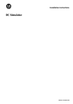
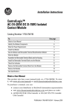
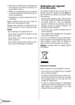
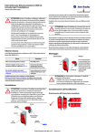
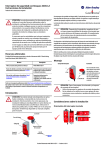
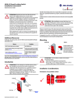
Installation Instructions
Pico DeviceNet Communication Module
1760-DNET
A
User Manual
1760-UM003
ATTENTION! Electrical Shock Hazard
Only qualified personnel may perform this
installation.
Observe all electrical safety requirements,
including any applicable laws, regulations, codes and
standards when installing this equipment.
Lebensgefahr durch elektrischen Strom!
Nur Elektrofachkräfte und elektrotechnisch unterwiesene Personen dürfen die im Folgenden beschriebenen
Arbeiten ausführen.
Die Stromversorgungsgeräte sind Einbaugeräte.
Beachten Sie für die Installation der Geräte die
länderspezifischen Vorschriften.
Tension électrique dangereuse !
Seules les personnes qualifiées et averties doivent
exécuter les travaux ci-après. Les blocs d’alimentation
sont des appareils faisant partie intégrante d’une
installation. Veuillez respecter les normes de mise en
œuvre spécifiques aux différents pays.
Tensione elettrica: Pericolo di morte!
Solo persone abilitate e qualificate possono eseguire
le operazioni di seguito riportate. Gli alimentatori
sono unità per montaggio interno. Per l’installazione
degli apparecchi è necessario rispettare le normative
specifiche di ciascun paese.
MS
NS
¡Corriente eléctrica! ¡Peligro de muerte!
El trabajo a continuación descrito debe ser realizado
por personas cualificadas y advertidas. Las fuentes de
alimentación son aparatos de montaje. Para la
instalación de los aparatos han de tenerse en cuenta
las normativas/especificaciones a nivel local.
Publication 1760-IN011B-MU-P
1760-DNET
f
e
a
b
c
d
e
f
DeviceNet connection, 5-pole plug connector
Power supply 24 V DC
Component label
NS-LED (network status)
MS-LED (module status)
Central Connection
a
b
c
d
e
f
Collegamento DeviceNet, connettore maschio 5 poli
Alimentazione 24 V DC
Targhetta apparecchio
NS-LED (stato rete)
MS-LED (stato modulo)
Collegamento locale
a
b
c
d
e
f
DeviceNet-Anschluss, 5-polige Stiftleiste
Spannungsversorgung Gerät 24 V DC
Gerätekennzeichnungsschild
NS-LED (Network Status)
MS-LED (Module Status)
Zentrale Kopplung
a
b
c
d
e
f
Conexión DeviceNet, conector macho 5 polos
Alimentación de tensión aparato 24 V DC
Indicador aparato
NS-LED (estado red)
MS-LED (estado módulo)
Acoplaniento centralizado
a
b
c
d
e
f
Connexion DeviceNet, connecteur mâle 5 pôles
Alimentation 24 V CC
Etiquette d’appareil
DEL NS (état réseau)
DEL MS (état module)
Connecteur pour module d’cotension local
a
d
c
b
Standard connection – Standardanschluss – Raccordement standard – Collegamento standard – Conexión estándar
+24 V
0V
>1A
+24 V 0 V
Central expansion – Zentrale Erweiterung – Extension centralisée – Espansione locale – Ampliación centralizada
Fitting
1
+
Einbau
1
+
Montage
1
2
, removing
2
, Ausbau
+
2
Montaggio
1
+
Montaje
+
2
1
3
+
4
+
4
, démontage
3
2
3
, smontaggio
, desmontaje
3
Devices must be de-energized!
Geräte müssen spannungsfrei sein!
+
4
3
+
+
4
Assurer la mise hors tension des appareils !
4
Gli apparecchi non devono essere alimentati!
¡Los aparatos deben encontrarse libres de tensión!
1
2
4
3
2/8
Connection – Anschluss – Raccordement – Collegamento – Conexión
Expansion Connector
1760-L18...
1760-L20...
1760-LDF...
1760-DNET
DeviceNet
1
1
V–
2
2
CAN_L
3
3
Shield
4
4
CAN_H
5
V+ (24 V)
5
0
1
. . .
n
DeviceNet
RT
RT
RT 120 O
DeviceNet Specification
3/8
Addressing – Adressierung – Adressage – Indirizzamento – Direccionamiento
Initial commissioning – Erstinbetriebnahme – Première mise en service – Prima messa in servizio – Primera puesta en servicio
1
Apply voltage to 1760-L18..., 1760-L20..., 1760-LDF..., 1760-DNET.
Remove DN connector or interrupt data exchange and set the basic unit into STOP mode.
1760-L18..., 1760-L20..., 1760-LDF..., 1760-DNET mit Spannung versorgen.
Entfernen sie den DN-Stecker oder brechen Sie den Datenaustausch ab und setzen Sie das Grundgerät in den STOP-Modus.
Mise sous tension de 1760-L18..., 1760-L20..., 1760-LDF..., 1760-DNET.
Retirer le connecteur DN ou arrêter l’échange de données et mettre l’appareil en mode d’arrêt.
Alimentare 1760-L18..., 1760-L20..., 1760-LDF..., 1760-DNET.
Rimuovere collegamento DN o interrompere scambio dati e impostare l’apparecchio di base nella modalità STOP.
Alimentar con tensión 1760-L18..., 1760-L20..., 1760-LDF..., 1760-DNET.
Quitar el conector DN o interrumpir el intercambio de datos y colocar el aparato base en el modo STOP.
2a
1760-L18..., 1760-L20...
GB
D
F
E
I
P
NL
S
PL
TR
+
O
2b
P
CONFIGURATOR
P
P
P
CONFIGURATOR
P
P
3
Pico GFX
+
O
DEVICENET
3
(MAX 63)
MAC-ID
0063
P
P
LINK
P
P
3
DeviceNet address 000 ... 63
DeviceNet-Adresse 000 ... 63
Adressage DeviceNet 000 ... 63
Indirizzo DeviceNet 000 ... 63
Dirección DeviceNet 000 ... 63
2 . . . 9 0 1 . . .
o
0 0 1
P 0 0 1
p
O
1 0 9 . . . 2 . . .
Accept address – Adresse übernehmen – Accepter adressage – Accettare indirizzo – Aceptar dirección
Exit – Abbruch – Quitter le menu – Cancella – Interrupción
4/8
CONFIGURATOR
KONFIGURATOR
PARAMETRAGE
CONFIGURADOR
ESPANSIONI
CONFIGURADOR
CONFIGURATOR
KONFIGURATOR
KONFIGURATOR
AYARLAR
1760-DNET
The two-colour LED can show GREEN or RED. – Die zweifarbige LED kann GRÜN oder ROT leuchten. – La DEL bicolore peut présenter la couleur VERTE ou la couleur ROUGE. –
I LED di indicazione possono assumere colore verde o rosso. – El LED bicolor puede iluminarse en VERDE o ROJO.
Module Status LED (MS) – Modul Status LED (MS) – DEL état module (MS) – LED stato modulo (MS) – LED estado módulo (MS)
a
t
b
t
c
t
d
a
b
c
d
e
f
OFF
GREEN
Flashing GREEN
Flashing RED
RED
Flashing GREEN-RED
No power supply present
Device is operating normally.
Standby – Configuration incorrect, incomplete or not yet carried out.
Error – Can be eliminated. Replacement not necessary.
Error – Cannot be eliminated. Device must be replaced.
Self test
a
b
c
d
e
f
AUS
GRÜN
GRÜN blinkend
ROT blinkend
ROT
GRÜN-ROT blinkend
Keine Spannungsversorgung vorhanden
Das Gerät arbeitet normal.
Standby – Konfiguration falsch, unvollständig oder noch nicht erfolgt.
Störung – Kann behoben werden. Austausch nicht nötig.
Störung – Nicht zu beheben. Gerät muss ausgetauscht werden.
Selbsttest
a
b
c
d
e
f
ETEINTE
VERTE
VERTE clignotante
ROUGE clignotante
ROUGE
VERTE/ROUGE clignotante
Absence de tension d’alimentation
Fonctionnement normal de l’appareil.
Attente – Configuration incorrecte, incomplète ou non réalisée.
Défaut – Possibilité d’élimination. Remplacement inutile.
Défaut – Elimination impossible. Remplacer l’appreil.
Auto-test
a
b
c
d
e
f
SPENTO
VERDE a luce fissa
VERDE a luce lampeggiante
ROSSO a luce lampeggiante
ROSSO a luce fissa
VERDE-ROSSO
a luce lampeggiante
Alimentazione non presente.
Funzionamento normale.
Standby – Configurazione non corretta o incompleta.
Errore – Può essere eliminato. Sostituzione non necessaria.
Errore – Non può essere eliminato. Il dispositivo va sostituito.
Il dispositivo è in auto-diagnosi.
a
b
c
d
e
f
OFF
VERDE
VERDE, parpadeo
ROJO, parpadeo
ROJO
VERDE-ROJO, parpadeo
Sin alimentación de tensión
El aparato funciona correctamente.
Pausa – Configuración errónea, incompleta o por realizar.
Avería – Puede repararse. Recambio no necesario.
Avería – No puede repararse. El aparato debe reemplazarse.
Autotest
t
e
t
f
t
Network Status LED (NS) – Network Status LED (NS) – DEL état réseau (NS) – LED stato rete (NS) – LED estado red (NS)
a
t
b
t
c
t
d
a
b
c
d
e
f
OFF
Flashing GREEN
GREEN
Flashing RED
RED
Flashing GREEN-RED
No power supply present. Device not online.
Device online. No connection made.
Device online. Connection made.
At least one I/O connection is in time-out state.
Critical connection error. Communication interrupted.
The device has detected a network access error and is in communication-error status.
a
b
c
d
e
f
AUS
GRÜN blinkend
GRÜN
ROT blinkend
ROT
GRÜN-ROT blinkend
Keine Spannungsversorgung vorhanden. Gerät nicht online.
Gerät online. Keine Verbindung hergestellt.
Gerät online. Verbindung hergestellt.
Mindestens eine I/O-Verbindung befindet sich im Time-Out-Status.
Kritischer Verbindungsfehler. Kommunikation abgebrochen.
Das Gerät hat einen Netzwerkzugangsfehler erkannt und befindet sich im
Communication-Fault-Status
a
b
c
d
e
f
ETEINTE
VERTE clignotante
VERTE
ROUGE clignotante
ROUGE
VERTE/ROUGE clignotante
Absence de tension d’alimentation. Appareil non connecté.
Appareil connecté. Absence de liaison.
Appareil connecté. Liaison réalisée.
Au moins une liaison E/S se trouve en état « Timeout ».
Défaut de liaison critique. Communication interrompue.
L’appareil a détecté un défaut d’accès au réseau et se trouve en état de défaut de
communication (Communication-Fault-Status).
a
b
c
d
e
f
SPENTO
VERDE a luce lampeggiante
VERDE a luce fissa
ROSSO a luce lampeggiante
ROSSO a luce fissa
VERDE-ROSSO
a luce lampeggiante
Alimentazione non presente. Dispositivo non in linea.
Dispositivo in linea. Connessione non stabilita.
Dispositivo in linea. Connessione stabilita.
Almeno una connessione I/O si trova in stato di time-out.
Errore critico di connessione. Comunicazione interrotta.
Il dispositivo ha rilevato un errore di accesso alla rete, e si trova in uno stato
di errore di comunicazione.
a
b
c
d
e
f
OFF
VERDE, parpadeo
VERDE
ROJO, parpadeo
ROJO
VERDE-ROJO, parpadeo
Sin alimentación de tensión. El aparato no se encuentra en línea.
Aparato en línea. No se ha establecido ninguna conexión.
Aparato en línea. Conexión establecida.
Al menos una conexión I/O se encuentra en estado Time-Out.
Error grave de conexión. Se ha interrumpido la comunicación.
El aparato ha reconocido un error de acceso de red y se encuentra en estado
Communication-Fault.
t
e
t
f
t
5/8
Dimensions – Abmessungen – Dimensioni – Dimensiones
47.5
1.87“
56.5 2.22“
110 4.33“
3.54“
90
4.5 0.18“
102 4.02“
0.3“
45 1.77“
7.5
M4
7.5
0.3“
35.5 1.4“
67 2.64“
For More Information
For
Refer to this Document
Pub Number
A more detailed description of how to install and use your Pico GFX-70 controller.
Pico GFX-70 Controller User Manual
1760-UM002
An introduction to Pico GFX-70 programming.
Pico GFX-70 Controllers Quick Start
1760-QS002
A more detailed description of how to install and use your Pico controller.
Pico Controller User Manual
1760-UM001
A basic overview of Pico and an introduction to Pico programming.
Pico Controller Getting Results
1760-GR001
More information on proper wiring and grounding techniques.
Industrial Automation Wiring and Grounding Guidelines
1770-4.1
If you would like a manual, you can:
– download a free electronic version from the internet: www.ab.com/pico or www.literature.rockwellautomation.com
– order a printed manual by:
contacting your local distributor or Rockwell Automation representative
Weitere Informationen
Für
Siehe Dokument
Pub.-Nr.
Eine ausführlichere Beschreibung der Installation und Handhabung Ihrer
programmierbaren Steuerung Pico GFX-70.
Steuerung Pico GFX-70 Benutzerhandbuch
1760-UM002
Eine Einführung zur Programmierung von Pico GFX-70.
Kurzanleitung Pico GFX-70 Regler
1760-QS002
Eine ausführlichere Beschreibung der Installation und Handhabung Ihrer
programmierbaren Steuerung Pico.
Steuerung PicoTM Benutzerhandbuch
1760-UM001
Eine grundlegende Übersicht über Pico und eine Einführung in die
Pico-Programmierung.
Steuerung PicoTM Praxishandbuch
1760-GR001
Weitere Informationen über ordnungsgemäße Verdrahtungs- und Erdungsverfahren.
Richtlinien zur Verdrahtung und Erdung von industriellen
Automatisierungssystemen
1770-4.1DE
Zu diesem Produkt gibt es ein Benutzerhandbuch, das Sie wie folgt bestellen können:
– durch kostenloses Herunterladen vom Internet: www.ab.com/pico oder www.literature.rockwellautomation.com
– durch Bestellung:
bei Ihrem Distributor oder einer Niederlassung von Rockwell Automation in Ihrer Nähe
Pour en savoir plus
Pour
Lisez ce document
Référence
Plus de détails sur l’installation et l’utilisation de l’automate Pico GFX-70.
Module Pico GFX-70 Manuel utilisateur
1760-UM002
Introduction à la programmation du Pico GFX-70.
Guide rapide regulateurs Pico GFX-70
1760-QS002
Plus de détails sur l’installation et l’utilisation de l’automate Pico.
Module PicoTM Manuel utilisateur
1760-UM001
Présentation générale de Pico et introduction à la programmation Pico.
Module PicoTM Guide pratique
1760-GR001
Plus d’informations sur le câblage et les techniques de mise à la terre.
Directives de câblage et de mise à la terre pour
automatisation industrielle
1770-4.1FR
Pour vous procurer un manuel, vous pouvez :
– le charger gratuitement depuis le site Internet : www.ab.com/pico ou www.literature.rockwellautomation.com
– commander un manuel imprimé. Pour cela :
contactez votre distributeur local Rockwell Automation
6/8
Per ulteriori informazioni
Per
Vedere documento
N. Pub.
Avere descrizioni più dettagliate su come installare e usare il controllore Pico GFX-70.
Controllore Pico GFX-70 Manuale dell’utente
1760-UM002
Introduzione alla programmazione del Pico GFX-70.
Guida rapida regolatori Pico GFX-70
1760-QS002
Avere descrizioni più dettagliate su come installare e usare il controllore Pico.
Controllore PicoTM Manuale dell’utente
1760-UM001
Informazioni generali su Pico e sulla sua programmazione.
Controllore PicoTM Per essere operativi
1760-GR001
Avere ulteriori informazioni sui modi appropriati di cablaggio e della messa a terra.
Industrial Automation Wiring and Grounding Guidelines
1770-4.1IT
Se si desidera ricevere un manuale, è possibile:
– scaricare una versione elettronica gratis da internet al sito: www.ab.com/pico o www.literature.rockwellautomation.com
– ordinare un manuale stampato:
contattando il distributore locale o rappresentante della Rockwell Automation
Para obtener más información
Para
Consulte este documento
Núm. de Publicación
Una descripción detallada sobre cómo instalar y usar el controlador Pico GFX-70.
Controlador Pico GFX-70 Manual del usuario
1760-UM002
Introducción de la programación de Pico GFX-70.
Guida rápida controladores Pico GFX-70
1760-QS002
Una descripción detallada sobre cómo instalar y usar el controlador Pico.
Controlador PicoTM Manual del usuario
1760-UM001
Vista general de Pico e introducción a la programación Pico.
Controlador PicoTM Obtención de resultados
1760-GR001
Información adicional sobre las técnicas apropiadas de cableado y tierra.
Pautas sobre cableado y conexión a tierra de equipos de
automatización industrial
1770-4.1ES
Si quiere recibir un manual puede:
– descargar una versión electrónica gratis de la siguiente dirección de internet: www.ab.com/pico or www.literature.rockwellautomation.com
– pedir un manual impreso. Para hacer esto haga una de las siguientes cosas:
comuníquese con su distribuidor local o representante local de Rockwell Automation
7/8
HAZARDOUS LOCATION – CSA (Canadian Standards Association) Certification
This equipment is suitable for use in CLASS I, DIVISION 2, GROUPS A, B, C AND D
WARNING: “EXPLOSION HAZARD – DO NOT DISCONNECT WHILE CIRCUIT IS LIVE UNLESS AREA IS KNOWN TO BE NON-HAZARDOUS“
EMPLACEMENTS DANGEREUX – Certification CSA (Canadian Standards Association)
Cet équipement est acceptable pour utilisation dans les EMPLACEMENTS DANGEREUX DE CLASSE I, DIVISION 2, GROUPES A, B, C ET D
AVERTISSEMENT : « RISQUE D’EXPLOSION. NE PAS DÉBRANCHER TANT QUE LE CIRCUIT EST SOUS TENSION, A MOINS QU’IL NE S’AGISSE
D’UN EMPLACEMENT NON DANGEREUX »
www.rockwellautomation.com
Power, Control and Information Solutions Headquarters
Americas: Rockwell Automation, 1201 South Second Street, Milwaukee, WI 53204-2496 USA, Tel: (1) 414.382.2000, Fax: (1) 414.382.4444
Europe/Middle East/Africa: Rockwell Automation, Vorstlaan/Boulevard du Souverain 36, 1170 Brussels, Belgium, Tel: (32) 2 663 0600, Fax: (32) 2 663 0640
Asia Pacific: Rockwell Automation, Level 14, Core F, Cyberport 3, 100 Cyberport Road, Hong Kong, Tel: (852) 2887 4788, Fax: (852) 2508 1846
Publication 1760-IN011B-MU-P January 2006
Supersedes 1760-IN011A-MU-P February 2005
Printed in Germany (10/07)
PN 40071-188-01(2)
© 2006 Rockwell Automation Inc.
All rights reserved.
Doku/Eb