1
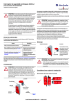
440G-LZ Guard Locking Switch Installation Instructions Original instructions in English ATTENTION: Read this document and the documents listed in the Additional Resources section about installation, configuration and operation of this equipment before you install, configure, operate or maintain this product. Users are required to familiarize themselves with installation and wiring instructions in addition to requirements of all applicable codes, laws, and standards. Activities including installation, adjustments, putting into service, use, assembly, disassembly, and maintenance are required to be carried out by suitably trained personnel in accordance with applicable code of practice. If this equipment is used in a manner not specified by the manufacturer, the protection provided by the equipment may be impaired. This 440G-LZ Guard Locking switch is for use on guards that are engineered so as to be rigid without sag. A separately mounted latch (e.g. magnetic, mechanical) and mechanical stop is required. Installation must be in accordance with these instructions and must be carried out by qualified personnel. ATTENTION: After installation, ensure that there is no possibility of lifting the actuator over the extended locking bolt. Adherence to the recommended maintenance instructions forms part of the warranty. This device is intended to be part of the safety-related control system of a machine. Before installation, a risk assessment must be performed to determine whether the specifications of this device are suitable for all foreseeable operational and environmental characteristics of the application. Refer to the Specifications for certification information and ratings. Use appropriate screws, bolts, or nuts fitted by tools to mount the switch and actuators to avoid the risk of tampering. Do not over torque the mounting hardware. Additional Resources The QR Code on the switch provides a link to the 440G-LZ Guard Locking Switch User Manual (440G-UM001A-EN-P). Mounting Switch body Resource Description 440G-LZ Guard Locking Switch User Manual 440G-UM001A-EN-P Industrial Automation Wiring and Grounding Guidelines, publication 1770-4.1 Provides general guidelines for installing a Rockwell Automation industrial system. Product Certifications website, http:// www.rockwellautomation.com/products/certification Provides declarations of conformity, certificates, and other certification details. 2 x M5/M6 CSK ATTENTION: For the switch, actuator and actuator mounting bracket: • Only use the designated mounting holes. • Never drill or use to support other structures such as conduit, cable ways, or other hardware. Introduction ATTENTION: Do not attempt to install this device unless the installation instructions have been studied and understood. This document acts as a guide for a typical installation and is available in some languages at www.rockwellautomation.com/literature. Select the publication language and type “440G-LZ” in the search field. A full user manual is also available. Installation Considerations Orientation of assembled switch Actuator Locking bolt QR Code Actuator mounting bracket Rockwell Automation 440G-IN011B-EN-P — June 2015 Alignment guide For proper installation, a minimum of two fasteners must be used, at least one of which must be fitted to the top row of holes, closest to the bend in the actuator mounting bracket. 3 x M5 You can view or download publications at http://www.rockwellautomation.com/literature/. To order paper copies of technical documentation, contact your local Allen-Bradley distributor or Rockwell Automation sales representative. Switch body Actuator 2 440G-LZ Guard Locking Switch Actuator setting Four directions of approach. ATTENTION: After installation, ensure that there is no possibility of lifting the actuator over the extended locking bolt. IMPORTANT IMPORTANT The locking bolt must always enter the actuator mounting bracket first. It might be easier to achieve actuator alignment by mounting only the actuator mounting bracket first to the guard/door and then finally fit the actuator to its mounting bracket. It is not possible to mechanically extend the locking bolt during installation, this can only be done electrically (see Commissioning in the user manual). Auxiliary/Manual Release [mm (in.)] Operation of the auxiliary release will cause a fault condition. To reset the switch, cycle the power. Align the white triangles 2.5 (0.098) dia. 2 x T10 Torx screws 0.4 Nm Actuator mounting (Three methods) 1. By setting gap “G” 2.5 mm (0.09 in.) [0…5 mm (0…0.19 in.)] 2. By mounting hole alignment”H” 6.5 mm (0.25 in.) [4…9 mm (0.15…0.35 in.)] 3. By use of the Alignment Guide Rockwell Automation 440G-IN011B-EN-P — June 2015 G H ATTENTION: After installation, ensure that there is no possibility of collision when the actuator approaches the switch body. 440G-LZ Guard Locking Switch 3 Dimensions [mm (in.)] Connections 9.525 (0.37) dia. 9.5 (0.37) 33 (1.29) 2 x 5.5 (0.22) dia. 25 (0.98) 45 (1.77) 22.5 (0.89) 10 (0.39) 134.5 (5.29) 8 (0.31) 140 (5.51) 40 (1.57) 65 (2.56) 47 (1.85) 12.5 7 (0.28) 25 (0.98)(0.5) Refer to the user manual for configuring Unique Actuators Rockwell Automation 440G-IN011B-EN-P — June 2015 Color 22.9 (0.90) 40 (1.57) 6 x 6.35 (0.25) dia. 5 Safety A 8-Pin Micro (M12) 51.5 (2.03) 25.4 (1.0) 4 Safety B+ 22.5 (0.88) 10 (0.39) 50 (1.97) 3 Lock Command 8 Safety A+ 3 (0.12) 8-pin cordset 889D-F8AB-* or cable version Function 2 24V DC+ Keyway 1 Aux 7 0V 6 Safety B Pin White Aux 1 Brown 24V DC+ 2 Green Lock 3 Yellow Safety B+ 4 Grey Safety A 5 Pink Safety B 6 Blue Gnd/0V 7 Red Safety A+ 8 4 440G-LZ Guard Locking Switch Specifications Standards IEC 60947-5-3, IEC 60947-5-1, IEC 61508, EN ISO 13849-1, IEC 62061, ISO 14119, UL 508 Operating Characteristics (continued) Safety Classification: Guard door sensing and lock monitoring PLe Category 4 per ISO 13849-1, SIL 3 per IEC 61508 and IEC 62061 Impulse withstand voltage Uimp (IEC 60947-1) 1 kV Pollution degree (IEC 60947-1) 3 PFHd: 9.1 x 10⁻¹⁰; Dual channel interlock can be suitable for use in Functional Safety Data: Guard door sensing and lock application up to PLe (according to ISO 13849-1) and for use up to monitoring SIL3 systems (according to IEC 62061 and IEC 61508) depending on application characteristics. Mission time/PTI: 20 years CE Marked for all applicable EU directives, cULus (UL 508), TÜV, CCertifications tick Operating Characteristics Torque for M5 mounting of switch and actuator 2 Nm max. mounting bracket Locking bolt insertion for assured locking & holding Min. of 5 mm (0.19 in.), max. of 10 mm (0.39 in.) force Locking bolt alignment tolerance X, Y, Z Max. of ±2.5 mm (0.09 in.) Holding Force Fmax (EN/ISO 14119) 1,690 N Holding Force Fzh (EN/ISO 14119) 1,300 N Maximum output current (each outputs) 200 mA Quiescent power consumption, locked or unlocked 2.5 W Peak current and duration, at turn on or after lock/ 400 mA / 100 ms unlock operation Operating voltage Ue 24V DC +10% / -15% Class 2 SELV Maximum frequency of operating cycles 0.2 Hz Manual (auxiliary) release Built in Protection class (IEC 61140) Class II Mechanical life 500,000 cycles Outputs (Guard door closed and locked) Safety Outputs Auxiliary Outputs Environmental Operating temperature [C (F)] Storage temperature [C (F)] 2 x PNP, 0.2 A max / ON (+24V DC) 1 x PNP, 0.2 A max / OFF (0V DC) 0…+55° (+14…+131°) -25…+75° (-13…+167°) Operating humidity 5…95% relative Enclosure ingress rating Shock and vibration NEMA 3, 4X, 12, 13, IP66, IP67, IP69k IEC 60068-2-27 30 g, 11 ms/IEC 60068-2-6 10…55 Hz ISO 14159:2004 and EN 1672-2005, (for that part of the machine defined as “food splash area”) Sodium Hydroxide based washdown fluids IEC 60947-5-3, FCC-1(Parts 18&15), R&TTE Dwell time between subsequent locking/unlocking 2.5 s Hygienic Response time (Off) Risk Time (according to IEC 60947-5-3) Start up time (availability) Maximum length of a chain of switches Utilization category (IEC 60947-5-2) 100 ms first switch, 50 ms additional for each switch 100 ms 5s 10 km (Dependent on cable/connection/required response time) DC-13 24V 200 mA Washdown Radio frequency / EMC General Materials Weight switch/actuator Insulation voltage Ui (IEC 60947-1) 75V Protection Type ABS, locking bolt and mounting bracket 304 stainless steel Switch 400 g, actuator 150 g, actuator mounting bracket 60 g Short-circuit, current limitation, overload, reverse polarity, overvoltage (up to 60V max.), thermal shutdown/restart Status/Diagnostic Operating LED Indicators The switch has two pairs of LEDs, status LEDs are green and diagnostic LEDs are red. Power to Lock Versions Door/Guard Status Lock Command OSSD Input Lock Status LED Status OSSD Status Power on and lock command off Lock command on and door open Lock command on and door closed Lock command on and door closed Open or closed Open Closed Closed Off On On On Off or on Off or on Off On Unlocked Unlocked Locked Locked Blinks 6 x green then solid red Fast flash green Slow flash green Solid green Off Off Off On Power to Release Versions Door/Guard Status Unlock Command OSSD Input Lock Status LED Status OSSD Status Power on with door open Open Off Off or on Unlocked Power on with door closed Closed Off Off Locked Off On Locked On Off or on Unlocked Power on with door closed and OSSD input Closed active Unlock command on and door closed or open Open or closed Blinks 6 x green then 1 x blink red followed by fast flash green Blinks 6 x green then 1 x blink red followed by slow flash green Blinks 6 x green then 1 x blink red followed by solid green Solid red Off Off On Off Catalog Numbers for Complete Switches 440G-LZS21 a S U a Standard Coding Unique Coding b c d P T b Auxiliary—Lock Status Auxiliary—Door Proximity R L c Power-to-Release Power-to-Lock A B H d 3 m Cable 10 Cable M12 8-pin Allen-Bradley and Rockwell Automation are trademarks of Rockwell Automation, Inc. Trademarks not belonging to Rockwell Automation are property of their respective companies. Publication 440G-IN011B-EN-P — June 2015 Copyright © 2015 Rockwell Automation, Inc. All rights reserved. Printed in the USA.