1
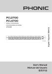
PCL2700
PCL4700
PCL 2700
PCL 4700
User's Manual
Manual del Usuario
English
PCL 2700
PCL 4700
Singal Processors
Español
PROCESADORES DE SEÑAl
ENGLISH . . . . . . . . . . . . . . . . . . . . . . . . . . . . . . . . . . . . . . . . . . . . . . . . . . I
ESPAÑOL ..................................................II
V1.1 06/01/2012
English
USER'S MANUAL
CONTENTS
INTRODUCTION
1
FEATURES
1
PRODUCT DESCRIPTION
1
EXPANDER/GATE
1
COMPRESSOR
2
DE-ESSER SECTION (PCL2700 ONLY)
2
PEAK LIMITER SECTION
3
INPUTS AND OUTPUTS
3
SPECIFICATIONS
4
APPENDIX
APPLICATIONS
1
Phonic preserves the right to improve or alter any information within this
document without prior notice
PCL2700 / PCL4700
IMPORTANT SAFETY INSTRUCTIONS
English
The apparatus shall not be exposed to dripping or splashing and that no objects
with liquids, such as vases,
shall be placed on the apparatus. The MainS plug is used as the disconnect device, the disconnect device shall
remain readily operable.
Warning: the user shall not place this apparatus in the
can be easily accessible.
area during the operation so that the mains switch
1. read these instructions before operating this
apparatus.
CAUTION
2. Keep these instructions for future reference.
RISK OF ELECTRIC SHOCK
DO NOT OPEN
. Heed all warnings to ensure safe operation.
4. Follow all instructions provided in this document.
5. Do not use this apparatus near water or in locations
where condensation may occur.
6. Clean only with dry cloth. Do not use aerosol or liquid
cleaners. Unplug this apparatus before cleaning.
7. Do not block any of the ventilation openings. install
in accordance with the manufacturer’s instructions.
CaUTion: To reDUCe THe riSK oF eLeCTriC SHoCK,
Do noT reMoVe CoVer (or BaCK)
no USer SerViCeaBLe ParTS inSiDe
reFer SerViCing To QUaLiFieD PerSonneL
The lightning flash with arrowhead symbol, within an
equilateral triangle, is intended to alert the user to the
presence of uninsulated “dangerous voltage” within the
product’
8. Do not install near any heat sources such as radiators,
heat registers, stoves, or other apparatus (including
.
9. Do not defeat the safety purpose of the polarized or
grounding-type plug. a polarized plug has two blades
with one wider than the other. a grounding type plug
has two blades and a third grounding prong. The wide
blade or the third prong is provided for your safety. if
the provided plug does not into your outlet, consult
an electrician for replacement of the obsolete outlet.
10. Protect the power cord from being walked on or
pinched particularly at plug, convenience receptacles,
and the point where they exit from the apparatus.
11. only use attachments/accessories
manufacturer.
magnitude to constitute a risk of electric shock to persons.
The exclamation point within an equilateral triangle is intended to alert the user to the presence of important operating and maintenance (servicing) instructions in the literature
accompanying the appliance.
WARNING: To reduce the risk of
or electric shock, do
not expose this apparatus to rain or moisture.
CAUTION: Use of controls or adjustments or performance
of procedures other than those
may result in
hazardous radiation exposure.
by the
12. Use only with a cart, stand, tripod, bracket, or
table
by the manufacturer, or sold with
the apparatus. When a cart is used, use caution
when moving the cart/apparatus
combination to avoid injury from tipover.
1. Unplug this apparatus during lighting
storms or when unused for long
periods of time.
14. refer all servicing to
service personnel.
Servicing is required when the apparatus has been
damaged in any way, such as power-supply cord or
plug is damaged, liquid has been spilled or objects
have fallen into the apparatus, the apparatus has
been exposed to rain or moisture, does not operate
normally, or has been dropped.
PCL2700 / PCL4700
PRODUCT DESCRIPTION
Congratulations on your purchase of another quality product! We
hope your PCL2700 or PCL4700 dynamic processor proves itself
to be a worthwhile investment and provides you with years of
dependable use. These processors were meticulously designed
by skilled engineers, and should give you total control of your
audio.
1. Couple Button
We know how eager you are to get started, however we advise
that you take the time to read through this manual before storing
it in an easy to remember place for future reference. Within
this manual you’ll find helpful information on the operation and
treatment of your PCL unit.
Pushing this button in will link the two channels of the PCL for
true stereo processing. When the channels are coupled, the
dynamics are then adjusted using the channel 1 controls. On the
PCL4700, channels 1 and 2 can be coupled and channels 3 and 4
can be coupled – in these cases, channels 1 and 3 will act as the
default control sections. The IN/OUT, SC EXT, SC MON, TUBE,
DEESSER, MALE, ENHANCER, I/O METER switches and the
OUTPUT, DE-ESSER LEVEL and ENHANCER LEVEL controls
are unaffected, however.
FEATURES
l
Program-adaptive compression circuitry with both hard- and
soft-knee properties
1
PCL2700
1
PCL4700
lIntelligent Peak/Limiting circuitry combining aspects of clip and
limiter functions for more reliable protection and inaudibility
for peaks
l
Dynamic enhancer for exciting and lively audio even through
compression
2. Trigger Control
suppression
This control will adjust the threshold for the expander/gate function
between OFF and +10 dB. The expander will set in below your
selected threshold.
Switchable stereo coupling function
3. Indicators
lExpander/gate
l
EXPANDER/GATE
circuit with ratio control for cleaner noise
lAttack
and release times adjustable either automatically or
manually (PCL2700 only)
lIntegrated de-esser removes excessive sibilance from vocals
If the signal is below the value set by the Trigger control, the red
LED will light up. If the signal is above the adjusted value, the
green LED will light up.
(PCL2700 only)
4. Release Button
l
Classic tube simulation for adding warmth to your sound
(PCL2700 only)
l
6-segment LED meters for input/output levels (5-segment on
the PCL4700)
l
Balanced 1/4” TRS and XLR inputs and outputs
This will allow users to determine whether the PCL will have a
long or short release time, which will ultimately depend on your
requirements. Push the button in for a longer release time, ideal
for slowly decaying signals and signals with heavy reverb. Keep
the button released for a shorter reverb time, ideal for signals with
little to no reverb.
lAuto
l
bypass function in event of power outage
Ultra-low noise operation
5. Gate Button
The gate button will allow users to swap between the gate and
expander functions. When the button is pushed in, the gate is
active; when the button is released, the expander is. Use the
gate function to affectively mute all signals below the selected
threshold.
4
2
PCL2700 / PCL4700
5
English
INTRODUCTION
7
9
11
1
17
18 21 22
4
11
1 17 18
English
6
8 10
12 14 15
2 5 6
16 19 20 2
10
16 19
PCL2700
PCL4700
COMPRESSOR
15. Release Control (PCL2700 only)
6. Threshold Control
This control will adjust the compressor ’s threshold between -40
and +20 dB.
By adjusting this control, users can select the time it will take for
the compressor to disengage after the gain drops below the level
set by the threshold. Users can adjust the range between 0.05
and 5 seconds.
7. Indicators (PCL2700 only)
16. Output Control
If the signal is below the value set by the threshold control, the
LED on the left will light up. If the signal is
This control allows users to increase and attenuate the output
signal of the PCL by up to 20 dB, ensuring users can compensate
for any gain loss caused by compression.
above the adjusted value, the LED on the right will. The center
yellow LED refers to the Interactive Knee soft-knee range (if
activated).
8. Sidechain External Button (PCL2700 only)
Pushing this button in will interrupt the signal between the input and
the compressor. When this is done, using the SC Return input on
the rear of the device to connect an external control signal.
9. Sidechain Monitor Button (PCL2700 only)
By pushing this button, the input signal from the sidechain will be
linked to the audio output, thus muting the audio input signal. When
the SC Monitor switch is activated, only the sidechain signal will be
sent to the outputs, which will be indicated by a flashing LED.
10. Ratio Control
This control will adjust the ratio of input to output, with regards to
all signals that exceed the threshold by 10Db or more. The auto
hard-knee/soft-knee function ensures level, inaudible activation
of the compressor function.
11. Gain Reduction Display
This 8 digit display (6 digit on the PCL4700) gives you a visual
representation of the gain reduction currently applied to your signal
(between 1 and 30 dB).
17. Level Meter
This 6-segment (5-segment on the PCL4700) level meter gives
users a visual indication of the incoming and outgoing audio levels
between -30 and +18 dB (-24 and +18 on the PCL4700), depending
on the setting of the Level Meter Input/Output Button.
18. Level Meter Input/Output Button
This button allows the user to decide whether they want to see
the input level (when the button is engaged) or the output level
(when the button is disengaged) in the level meter.
19. In/Out Switch
This button activates the corresponding channel. It also activates a
“hard bypass” of the corresponding channel, meaning that – even
without power – the input signal will be sent directly to the output.
A common function of this button is to compare the processed and
unprocessed signals instantly.
DE-ESSER SECTION (PCL2700 only)
The De-esser function – available on the PCL2700 – is only active
if the compressor function is used.
12. Attack Control (PCL2700 only)
20. Level Control
This control will allow users to determine when compression will
set in after the signal level has exceeded the threshold.
Adjusting this control will allow users to determine the amount of
frequency suppression to be used.
13. Interactive Knee Button
21. De-esser Level Meter
This button will activate the “interactive knee” function. When
active, input signals that are 10dB over the threshold will be
processed with ‘soft-knee’ compression. At all other times, hardknee compression will be active. The interactive knee function
allows for more discreet compression of music and should be
activated when inaudible compression is needed.
This meter gives a visual representation of the current attenuation,
between +3 and +12 dB.
14. Auto Button (PCL2700 only)
By pushing this button in, the attack and release buttons on the
PCL2700 will become effectively disabled. The attack and release
times will then be determined automatically, according to the
complexity of musical aspects of the audio received.
22. Male Switch
The button will adapt the de-esser function to both male (pushed
in) and female (released) voices.
23. In/Out Switch
This button will turn the de-esser function off and on.
PCL2700 / PCL4700
PEAK LIMITER SECTION
25
INPUTS AND OUTPUTS
27. AC Power Inlet and Fuse Holder
25
28. Output Connectors
These balanced XLR and 1/4” outputs are used to send the main
output signal of the PCL to external devices.
24
24
PCL2700
PCL4700
29. Input Connectors
These XLR and 1/4” inputs accept balanced and unbalanced
signals, and feed them to the PCL’s expander/ gate, compressor,
de-esser and limiter functions.
24. Peak Limiter Control
This control allows users to determine when the peak/ limiter
function will kick in ie. to what level the audio level will be limited.
Turning it all the way to the right will effectively disable the
limiter. If the limiter function is active on a signal for more than 20
milliseconds, the signal’s gain will be reduced slightly to reduce
the risk of audible limiting. It’s advisable, however, to reduce the
levels set by the limiter and output controls (in the compression
section) to ensure this limiter activates rarely, if at all.
30. Operating Level Switch
This switch adjusts the PCL to different operating levels. If you
connect consumer-level (-10dB) equipment, this button should
be pushed in. If you are using professional gear (+4 dB), leave
it released.
31. Sidechain Send (PCL2700 only)
This balanced 1/4” output will allow users to route the signal to
other external devices. This signal can be processed and sent
back to the PCL through the sidechain return inputs.
25. Limit Indicator
This indicator will light up when the limiter
function is in use.
32. Sidechain Return (PCL2700 only)
26
26. Power Button
As described above, using the sidechain send will allow you to
send a signal to an external processing device, and return the
processed signal to the device through this balanced 1/4” input.
Flicking this switch turns the PCL on and off.
27
27
28
0
28
29
0
PCL2700 / PCL4700
29
1
2
English
This inlet is used to connect the provided AC power cable, the
other end of which is connected to a suitable power source. Check
local voltage levels are compatible before attempting to use this
device. The power supply’s fuse is imbedded in this socket. If for
some reason the fuse blows, please remove the fuse cover and
replace it with another suitable fuse.
SPECIFICATIONS
English
Model Name
PCL2700
PCL4700
AUDIO INPUTS
Type
Impedance
1/4” TRS and XLR connectors
+4
90kΩ balanced, 45kΩ unbalanced @ 1kHz
-10
180kΩ balanced, 90kΩ unbalanced @ 1kHz
Operating Level
+4/-10 dB (switchable)
Max Input Level
+22dBu, balanced and unbalanced
CMRR
typ. 40 dB, >60 dB @ 1 kHz
AUDIO OUTPUTS
Type
Impedance
Max Output Level
1/4” TRS and XLR connectors
95kΩ balanced, 50kΩ unbalanced @ 1kHz
+21dBu, +20 dBm balanced and unbalanced
SIDECHAIN INPUTS
Type
1/4” TS connectors
45Ω
Impedance
Max Input Level
+24dBu
SIDECHAIN OUTPUTS
Type
1/4” TS connectors
50Ω
Impedance
Max Output Level
+21dBu
SYSTEM SPECIFICATIONS
Badwidth
20 Hz - 20 kHz, +/- 0.5 dB
Frequency Range
10 Hz to 31 kHz, +0.5/-1dB
S/N Ratio
THD
IMD
Crosstalk
115dB unweighed, 22Hz - 22 kHz
0.008% @ +4dBu, 1 kHz, unity Gain
0.07% @ +20dBu, 1 kHz, unity Gain
(SMPTE) less than 0.01%
-89 dB, 20-20kHz, +4 dBu, channel-to-channel
EXPANDER/GATE SECTION
Type
Ratio-controlled
Threshold
OFF to +10 dB
Ratio
Attack
Release
1:1 to 1:8
<1 msec/50 dB (depends on program)
Variable: slow (100 ms/1 dB) to fast (100 ms/100 dB)
COMPRESSOR SECTION
Type
Threshold
Automatic Soft/Hard Knee Compression
-40 to +20 dB
1:1 to ∞:1
Ratio
Attack/Release
Auto Characteristics
Manual or automatic
Automatic
Adpative
PCL2700 / PCL4700
0.3msec/20 dB to 300 msec/
20dB
N/A
Manual Release Time
0.05sec/20 Db to 5sec/20dB
N/A
Auto Attack Time
English
Manual Attack Time
15 msec for 10 dB, 5 msec for 20dB
Auto Release Time
Depends on program, typ. 125 dB/sec
Output
-20 dB to +20 dB
PEAK LIMITER SECTION
Type
Gain controllable
Level
0 dB to OFF (+21 dBu)
Ratio
∞:1
Level
1 Limiter Type Clip
Attack
0
Release
0
Level 2 Limiter Type
Program limiter
Attack
Depends on program, typ. <5 msec
Release
Depends on program, typ. 20dB/sec
DE-ESSER SECTION
Type
Adaptable to voice
N/A
Filter Frequency
9.5 kHz (female), 7.8 kHz
(male)
N/A
Filter Bandwidth
Depends on program
N/A
Level Reduction
Maximum: 15 dB
N/A
Interactive
N/A
Filter Frequency
2.5 kHz (Low cut-off freq.)
N/A
Characteristic
High pass filter (6 dB/oct)
N/A
Max. 28 dB @ 7.5 kHz
N/A
DYNAMIC ENHANCER SECTION
Type
Boost
POWER SUPPLY
Mains Voltage
North
America
120V, 60Hz
UK/
Australia
240V, 50Hz
Europe
230V, 50Hz
General Export Model
100V - 120V, 200 - 240V, 50 - 60 Hz
Power Consumption
Fuse
Maximum: 15W
Maximum: 18W
100-120V
1A
200-240V
T500mAH
PHYSICAL
Dimensions
Weight 2.1 kg
PCL2700 / PCL4700
44.5 x 482.6 x 217 mm (1.75” x 19” x 8.5”)
2.1 kg (4.63 lbs)
2.25 kg(4.96 lbs)
SERVICE AND REPAIR
English
For replacement parts, service and repairs please contact the Phonic distributor in your
country. Phonic does not release service manuals to consumers, and advice users to not
attempt any self repairs, as doing so voids all warranties. You can locate a dealer near you at
http://www.phonic.com/where/.
WARRANTY INFORMATION
Phonic stands behind every product we make with a no-hassles warranty. Warranty coverage
may be extended, depending on your region. Phonic Corporation warrants this product for a
minimum of one year from the original date of purchase against defects in material and
workmanship under use as instructed by the user’s manual. Phonic, at its option, shall repair
or replace the defective unit covered by this warranty. Please retain the dated sales receipt as
evidence of the date of purchase. You will need it for any warranty service. No returns or repairs
will be accepted without a proper RMA number (return merchandise authorization). In order to
keep this warranty in effect, the product must have been handled and used as prescribed in the
instructions accompanying this warranty. Any tampering of the product or attempts of self repair
voids all warranty. This warranty does not cover any damage due to accident, misuse, abuse,
or negligence. This warranty is valid only if the product was purchased new from an authorized
Phonic dealer/distributor. For complete warranty policy information, please visit
http://www.phonic.com/warranty/.
CUSTOMER SERVICE AND TECHNICAL SUPPORT
We encourage you to visit our online help at http://www.phonic.com/support/. There you can find
answers to frequently asked questions, tech tips, driver downloads, returns instruction and other
helpful information. We make every effort to answer your questions within one business day.
[email protected]
http://www.phonic.com
PCL2700 / PCL4700
English
Manual del Usuario
CONTENIDO
1
CARACTERÍSTICAS
1
DESCRIPCIÓN DEL PRODUCTO
1
EXPANSOR/PUERTA (EXPANDER/GATE)
1
COMPRESOR
2
SECCIÓN DEESSER (PCL2700 SOLAMENTE)
2
SECCIÓN DE LIMITADOR DE PICO
3
ENTRADAS Y SALIDAS
3
ESPECIFICACIONES
4
Español
INTRODUCCIÓN
Apéndice
APLICACIONES
1
Phonic se reserva el derecho de mejorar o alterar cualquier información
provista dentro de este documento sin previo aviso.
PCL2700 / PCL4700
English
Español
PCL2700 / PCL4700
DESCRIPCIÓN DEL PRODUCTO
Felicitaciones por su compra de otro producto de calidad!
Esperemos que su procesador dinámico PCL2700 o PCL4700
otorga en sí mismo una inversion que vale la pena y le provee a
usted con varios años de uso confiable. Estos procesadores son
meticulosamente diseñados por ingenieros capacitados y puede
darle un control total de su audio.
1. Botón Par
Sabemos que está ansioso comenzar, sin embargo, le
aconsejamos que tome el tiempo de leer este manual antes
guardarlo en un lugar de fácil acceso para futuras referencias. En
este manual, usted puede encontrar información útil acerca de la
operación y tratamiento de su unidad de PCL.
Presionando este botón se conectará con dos canales de PCL
para un procesamiento de estéreo verdadero. Cuando los
canales están acoplados, los dinámicos son ajustados usando
controles de canal 1. En PCL4700, los canales 1 y 2 pueden
ser acoplados y los canales 3 y 4 pueden acoplados – en estos
casos, los canales 1 y 3 actuarán como secciones de control por
default. Sin embargo, Los interruptores IN/OUT, SC EXT, SC
MON, TUBE, DEESSER, MALE, ENHANCER, I/O METER y los
controles OUTPUT, DEESSER LEVEL y ENHANCER LEVEL no
están afectados.
Español
CARACTERÍSTICAS
l
l
Sistema de circuitos de compresión de programaadaptivo con
propiedades de hard-knee y soft-knee.
Sistema de circuitos inteligente Pico/Limitativo combinando
aspectos de recortar y funciones de limitador para protección
más confiable e inaudibilidad para picos.
lRealzador
dinámico para audio emocionante y animado aún
por compresión
l
Circuito expansor/puerta con control de proporción para
limpiar ruido de supresión
l
Función de acoplamiento de estéreo intercambiable
lAtaque y l iberación de t iempos ajus tables, automáticamente
o manualmente (PCL2700 solamente)
l
Deesser integrado remueve sonido sibilante excesivo de los
vocales (PCL2700 solamente)
l
Tubo de simulación clásico para agregar afecto a su
sonido(PCL2700 solamente)
l
Medidores LED 6-segmento para niveles de entrada/salida
(5-segmento en PCL4700)
lEntradas
l
y salidas TRS balanceado 1/4” y XLR
Función de desviación automática en evento de corte de
electricidad temporal
lOperación
de ruido ultra-bajo
1
PCL2700
1
PCL4700
EXPANSOR/PUERTA
(EXPANDER/GATE)
2. Control Trigger
Este control se ajustará el umbral
para función de expansor/puerta entre
APAGADO(OFF) y +10 dB. El expansor
se seteará por debajo de su umbral
seleccionado.
4
3. Indicadores
Si la señal está debajo del valor configurado
por el control Trigger, el LED rojo se
encenderá. Si la señal está sobre el valor
ajustado, se encenderá el LED verde.
2
5
4. Botón Liberado
Éste le permitirá a los usuarios a determinar si el PCL tendrá
tiempo de liberación largo o corto, que dependerá de sus
necesidades. Presione el botón para tiempo de liberación más
largo, ideal para señales de descomposición lenta y señales con
resonancia fuerte. Mantenga el botón liberado para tiempo más
corto, ideal para señales con poca o sin resonancia.
5. Botón Puerta (Gate)
El botón puerta le permitirá a los usuarios cambiar entre funciones
de puerta y expansor. Cuando el botón está presionado, la puerta
está activada; cuando el botón está liberado, el expansor es el
activo. Use la function puerta para poner a sordina todas las
señales por debajo del umbral seleccionado.
PCL2700 / PCL4700
English
INTRODUCCIÓN
7
9
11
1
17
18 21 22
4
11
1 17 18
English
6
8 10
12 14 15
16 19 20 2
2 5 6
10
16 19
Español
PCL2700
PCL4700
COMPRESOR
15. Control de Liberación (PCL2700 solamente)
6. Control de Umbral
Este control se ajustará el umbral de compresor entre -40 and
+20 dB.
Ajustando este control, los usuarios pueden seleccionar el tiempo
que tomará el compresor para desenganchar luego de ganar
conexión de terminal debajo de nivel seteado por el umbral. Los
usuarios pueden ajustar el rango entre 0.05 y 5 segundos.
7. Indicadores (PCL2700 solamente)
16. Control de Salida
Si la señal está debajo del valor seteado por el control de umbral,
el LED de la izquierda se encenderá. Si la señal está encima del
valor ajustado, el LED de la derecha se encenderá. El LED amarillo
de centro referencia al rango de soft-knee de Knee Interactivo
(de ser activado).
Este control permite a los usuarios de incrementar y atenuar
la señal de salida de PCL encima de 20dB, asegurándo a los
usuarios de poder compensar por cualquier ganancia perdida
causada por la compresión.
8. Botón Externo de Cadena Lateral (Sidechain)
(PCL2700 solamente)
Presionando este botón se interrumpirá la señal entre la entrada
y el compresor. Cuando está hecho, usando la entrada de SC
Retorno sobre el reverso del dispositivo para conectar una señal
de control externa.
9. Botón Monitor de Cadena Lateral (Sidechain)
(PCL2700 solamente)
Presionando este botón, la señal de entrada desde cadena lateral
se conectará a la salida de audio, poniendo sordina a la señal
de entrada de audio. Cuando el interruptor de Monitor SC está
activado, solo la señal de cadena lateral se enviará a las salidas,
que serán indicadas por un LED intermitente.
10. Control de Proporción
Este control se ajustará la proporción de la entrada a la salidad,
con respecto a todas las señales excedidas a umbral por 10dB o
más. La función automática hardknee/soft-knee asegura el nivel,
la activación inaudible de la función de compresor.
11. Exhibidor de Reducción de Ganancia
Este exhibidor de 8 dígitos (6 dígitos en PCL4700) le da una
representacón visual de reducción de ganancia actualmente
aplicada a su señal (entre 1 a 30dB).
12. Control de Ataque (PCL2700 solamente)
Este control le permitirá a los usuarios a determiner cuando la
compresión se seteará luego de que el nivel de señal ha excedido
el umbral.
17. Nivel de Medidor
Este medidor de nivel de 6-segmento (5-segmento en PCL4700)
le proporciona a los usuarios una indicación visual de niveles
de audio entrante y saliente entre -30 y +18 dB (-24 y +18 en
PCL4700), dependiendo de la caonfiguración de Botón de
Entrada/Salida de Nivel de Medidor.
18. Botón Entrada/Salida de Nivel de Medidor
Este botón permite al usuario a decidir si quieren ver el nivel
de entrada (cuando el botón está activado) o el nivel de salida
(cuando el botón está desactivado) en el nivel de medidor.
19. Interruptor Entrada/Salida (In/Out)
Este botón activa el canal correspondiente. También activa un
“hard bypass” de canal correcpondiente, eso significa que –aún sin
energía- la señal de entrada se enviará directamente a salida. Una
función común de este botón es comparar las señales procesadas
y no procesadas inmediatamente.
SECCIÓN DEESSER
(PCL2700 solamente)
La función Deesser – disponible en PCL2700- se active solamente
si la función de compresor está en uso.
20. Control de Nivel
Ajustando este control permitirá a los usuarios a determinar la
cantidad de frecuencia de supresión a ser utilizado.
13. Botón Knee Interactivo
21. Medidor de Nivel Deesser
Este botón activará la función de ¨IK o interactive knee¨. Cuando
esta función está activada, las señales de entrada que son sobre
10dB umbral que serán procesados con la compresión¨suave¨.
Para cualquier momento, la compresión dura será activbada.
La función interactiva permitirá más discreción en relacionando
con la compresión de música y deberá ser activado cuando la
comprensión inaudiable sea necesario.
Este medidor proporciona una representación visual de atenuación
actual, entre +3 y +12dB.
14. Botón Automático (PCL solamente)
22. Interruptor Macho
Este botón adaptará la función deesser a las voces masculinas
(presionado) y femeninas (liberado).
23. Interruptor Entrada/Salida (In/Out)
Este botón apagará y encenderá la función deesser.
Con solo presionar este botón, los botones de ataque y liberación
en el PCL2700 será efectivamente incapacitado. Las veces
del ataque y liberación serán determinado automaticamente,
deacuerdo con la complejidad del punto de vista de audio
recivido.
PCL2700 / PCL4700
SECCIÓN DE LIMITADOR DE PICO
25
ENTRADAS Y SALIDAS
27. Energía de Entrada AC y Asidero de Fusible
25
28. Conectores de Salida
24
24
Estas salidas XLR balanceado y 1/4” son usadas para enviar la
sañal de salida principal de PCL a los dispositivos externos.
PCL4700
29. Input Connectors Conectores de Entrada
24. Control de Limitador de Pico
Estas entradas XLR y 1/4” aceptan señales balanceadas y no
balanceadas y, alimentarlas a las funciones de expansor/puerta,
compresor, deesser y limitador de PCL.
Este control permite al usuario en determinar cuando la función
del pico/limitador entran, por ejemplo: hasta que nivel de audio
será limitado. Rotandolo todo hasta la derecha efectivamente
incapacitará el limitador. Si la función de limitador es activado en
una señal por más de 20 millisegundos, la ganacia de la señal
será reducida un poco para reciducir la posibilidadd de limitado
audiable. Sin emgargo, sugerimos en reducir los niveles fijados
pore el limitador y salida (en las sección de compresión) para
asegurarle que este limitardor se active raras veces.
30. Interruptor de Nivel de Operación
Este interruptor ajusta PCL a diferentes niveles de operación.
Si us ted conecta equipo de nivel - consumidor ( -10dB) , es te
botón deber ía es tar presionado. Si usted está usando equipo
professional (+4 dB), déjelo liberado.
31. Envío de Cadena Lateral (Sidechain)
25. Indicador de Límite
(PCL2700 solamente)
Este indicador se encederá cuando la función limitador está en
uso.
Esta salida balanceada 1/4” permite a usuarios mandar la señal
a otros dispositivos externos. Esta señal puede ser procesada
y enviada de vuelta a PCL a través de entradas de retorno de
cadena lateral.
26. Botón de Energía
Presionando este interruptor se ensederá o
apagará el PCL.
26
32. Retorno de Cadena Lateral (Sidechain)
(PCL2700 solamente)
Como descripto anteriormente, usando envío de cadena lateral le
permitirá a usted enviar señal a un dispositivo de procesamiento
externo, y retorna la señal procesada al dispositivo mediante esta
entrada balanceada 1/4”.
27
27
28
0
28
29
0
PCL2700 / PCL4700
29
1
2
Español
PCL2700
English
Esta entrada es usada para conectar el cable de energía AC
provisto, su otra punta es conectada a una fuente de energía
compatible. Compruebe que los niveles de voltage local sea
compatible antes de usar este dispositivo. El fusible de suministro
de energía está fijado en este casquillo. Si por alguna razón el
fusible se explota, por favor remueve la cubierta de fusible y
reemplazarlo por otro fusible compatible.
ESPECIFICACIONES
English
Nombre de Modelo
PCL2700
PCL4700
ENTRADAS DE AUDIO
Tipo
Impedancia
Conectores 1/4” TRS y XLR
+4
90kWbalanceado, 45 kWno balanceado @ 1kHz
-10
180kWbalanceado, 90 kWno balanceado @ 1kHz
Nivel de Operación
Español
Nivel de Entrada Max
CMRR
+4/-10 dB (intercambiable)
+22dBu, balandeado y no balanceado
Tipo 40 dB, >60 dB @ 1kHz
SALIDAS DE AUDIO
Tipo
Impedancia
Nivel de Salida
Conectores 1/4” TRS y XLR
95kW balanceado, 50 kWno balanceado @ 1kHz
Max +21dBu, +20 dBm balandeado y no balanceado
ENTRADAS DE CADENA LATERAL
Tipo
Conectores 1/4” TS
Impedancia
Nivel de Entrada
45 W
Max +24dBu
SALIDAS DE CADENA LATERAL
Tipo
Conectores 1/4” TS
Impedancia
Nivel de Salida
50 W
Max +21dBu
ESPECIFICACIONES DEL SISTEMA
Ancho de banda
Rango de Frecuencia
Índice
THD
IMD
Interferencias
20 Hz – 20 kHz, +/- 0.5 dB
10 Hz a 31 kHz, +0.5/-1 dB
S/N 115dB no ponderado, 22Hz – 22 kHz
0.008% @ +4dBu, 1 kHz, unidad Ganancia
0.07% @ +20dBu, 1 kHz, unidad Ganancia
(SMPTE) less than 0.01%
-89 dB, 20-20kHz, +4 dBu, channel-to-channel
SECCIÓN EXPANSOR/PUERTA
Tipo
Índice controlado
Umbral
Hasta +10 dB
Índice
1:1 a 1:8
Ataque a)
< 1msec/50 dB (depende del program
Liberación
Variable:lento(100ms/1dB) a rápido(100ms/100 dB)
SECCIÓN COMPRESOR
Tipo
Compresión Automática Soft/Hard Knee
Umbral
-40 a +20 dB
Índice
1:1 to ∞:1
Ataque/Liberación
Características Auto
Tiempo de Ataque Manual
Manual o automático
Automático
Adaptivo
0.3mseg/20dB a 300 mseg/20
dB
N/A
PCL2700 / PCL4700
0.05seg/20 dB a 5seg/20dB
Tiempo de Ataque Auto
N/A
English
Tiempo de Liberación Manual
15 mseg para 10dB, 5mseg para 20dB
Tiempo de Liberación Auto
Depende de programa, tipo. 125 dB/seg
Salida
-20 dB a +20dB
SECCIÓN DE LIMITADOR DE CRESTA
Ganancia controlable
Nivel
0 dB a OFF (+21 dBu)
Índice
∞:1
Nivel
1 Tipo Limitador Clip
Ataque
0
Liberación
0
Nivel 2 Tipo Limitador
Español
Tipo
Programa Limitador
Ataque
Depende de programa, tipo. <5 mseg
Liberación
Depende de programa, tipo. 20dB/seg
SECCIÓN DEESSER
Tipo
Adaptable a voz
N/A
Frecuencia de Filtro
9.5kHz(mujer),
7.8kHz(hombre)
N/A
Depende de programa
N/A
Máximo: 15dB
N/A
Interactivo
N/A
2.5kHz(frecuencia baja de
corte)
N/A
Filtro de alto paso (6 dB/oct)
N/A
Max.28 dB @ 7.5 kHz
N/A
Ancho de Banda de Filtro
Reducción de Nivel
SECCIÓN CONEXIÓN DINÁMICA
Tipo
Frecuencia de Filtro
Característica
Incremento
SUMINISTRO DE ENERGÍA
Voltaje Pincipal
Norte
América
120V, 60Hz
UK/
Australia
240V, 50Hz
Europa
230V, 50Hz
Modelo de Exportación General
100V – 120V, 200-240V, 50-60 Hz
Consumo de Energía
Fusible
Máximo: 15W
Máximo: 18W
100-120V
1A
200-240V
T500mAH
FÍSICO
Dimensiones
Peso
PCL2700 / PCL4700
44.5 x 482.6 x 217 mm (1.75” x 19” x 8.5”)
2.1 kg (4.63 lbs)
2.25 kg(4.96 lbs)
SERVICIO Y REPARACIÓN
English
Para refacciones de reemplazo y reparaciones, por favor póngase en contacto con nuestro
distribuidor de Phonic en su país. Phonic no distribuye manuales de servicio directamente a los
consumidores y, avisa a los usuarios que no intenten hacer cualquier reparación por si mismo,
haciendo ésto invalidará todas las garantías del equipo. Puede encontrar un distribuidor cerca
de usted en http://www.phonic.com/where/.
Español
INFORMACIÓN DE LA GARANTIA
Phonic respalda cada producto que hacemos con una garantía sin enredo. La cobertura de
garantía podría ser ampliada dependiendo de su región. Phonic Corporation garantiza este
producto por un mínimo de un año desde la fecha original de su compra, contra defectos en
materiales y mano de obra bajo el uso que se instruya en el manual del usuario. Phonic, a su
propia opinión, reparará o cambiará la unidad defectuosa que se encuentra dentro de esta
garantía. Por favor, guarde los recibos de venta con la fecha de compra como evidencia de la
fecha de compra. Va a necesitar este comprobante para cualquier servicio de garantía. No se
aceptarán reparaciones o devoluciones sin un número RMA apropiado (return merchandise
autorization). En orden de tener esta garantía válida, el producto deberá de haber sido
manejado y utilizado como se describe en las instrucciones que acompañan esta garantía.
Cualquier atentado hacia el producto o cualquier intento de repararlo por usted mismo,
cancelará completamente esta garantía. Esta garantía no cubre daños ocasionados por
accidentes, mal uso, abuso o negligencia. Esta garantía es válida solamente si el producto fue
comprado nuevo de un representante/distribuidor autorizado de Phonic. Para la información
completa acerca de la política de garantía, por favor visite http://www.phonic.com/warranty/.
SERVICIO AL CLIENTE Y SOPORTE TÉCNICO
Le invitamos a que visite nuestro sistema de ayuda en línea en www.phonic.com/support/. Ahí
podrá encontrar respuestas a las preguntas más frecuentes, consejos técnicos, descarga de
drivers, instrucciones de devolución de equipos y más información de mucho interés. Nosotros
haremos todo el esfuerzo para contestar sus preguntas lo antes posible.
[email protected]
http://www.phonic.com
PCL2700 / PCL4700
APPLICATION
APLICACIÓN
Appendix
有源音箱
Apéndice
ACTIVE SPEAKER
ALTAVOZ ACTIVO
MIXER
MEZCLADORA
调音台
INTO YOUR CHANNEL'S
INSERT POINT
DENTRO DE SU CANAL
PUNTO DE INSERCIÓN
连接声道的插入点
PCL2700 / PCL4700