1
Hood
Body
Tab
Damper
NOTE: DO NOT disconnect any wiring that has already been crimped with a wire connector
from the factory.
2. Install the wire compartment cover and tighten screw. Make sure all wiring is securely
contained within the wire compartment.
E-22A/RCD7
SECTION 6
Ducting
CAUTION: ALL DUCTING MUST COMPLY WITH LOCAL AND NATIONAL
BUILDING CODES.
WARNING: TO REDUCE THE RISK OF FIRE, USE ONLY METAL DUCTWORK.
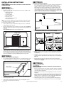
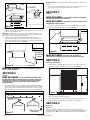
1. Connect the ducting to the hood’s duct collar and damper. Secure in place using tape to
seal all joints (Figure 8).
Figure 5
NOTE: If installing into existing construction and you will not have access to the ductwork
once the hood is in place, make ducting connections at this point. Refer to the Ducting Section
for instructions.
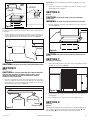
5. Install the 4 mounting screw at the previously marked locations. Leave approximately 1/8"
clearance. Slide the hood in place through the keyhole slots and align the front of the hood
so that it is flush with the front of the cabinets. Tighten all screws securely (Figure 6).
1/8"
Keyhole
Figure 8
CAUTION: ALWAYS DUCT THE FAN TO THE OUTSIDE THROUGH A WALL OR
ROOF CAP.
SECTION 7
Figure 6
Finishing the Installation
CAUTION: DO NOT INSTALL CLOSER THAN 22 INCHES ABOVE COOKING SURFACE.
1. Install the filter by fitting the filter into the channel on the hood and sliding it back until it
stops against the back of the hood (Figure 9).
SECTION 5
Wiring
CAUTION: ALL ELECTRICAL CONNECTIONS MUST BE MADE IN ACCORDANCE
WITH LOCAL CODES, ORDINANCES, OR NATIONAL ELECTRICAL CODE. IF YOU ARE
UNFAMILIAR WITH METHODS OF INSTALLING ELECTRICAL WIRING, SECURE THE
SERVICES OF A QUALIFIED ELECTRICIAN.
1. Connect the 2 loose Black wires from the range hood to the Black wire from the supply,
and the 2 loose White wires from the range hood to the White wire of the supply. Connect
the ground wire (green or bare) from the supply to the green ground screw of the hood.
Use approved methods for all connections (Figure 7).
Figure 9
2. Turn switches to the “OFF” position and restore power. Test that the light and the fan are
operating properly.
Hot (Black)
Figure 7
6728010 Rev A 10-13
Neutral (White)
Ground
(Green or Bare)
3. If there is any vibration noise, check for the source and try to tighten fasteners.
SECTION 8
Operation
Controls
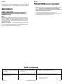
Your Range Hood is equipped with two rotary switches with one controlling the lighting and the
other controlling the exhaust fan. The light switch has three positions, Main Light ( ● ), Night
Light ( ◗ ), and OFF ( ■ ). The fan switch has three positions, High, Low, and OFF.
www.airkinglimited.com
3 of 12