1
SECTION 3
Wiring
Wiring Compartment Cover
CAUTION: MAKE SURE POWER IS SWITCHED OFF AT SERVICE PANEL BEFORE
STARTING INSTALLATION.
Wiring Compartment
CAUTION: ALL ELECTRICAL CONNECTIONS MUST BE MADE IN ACCORDANCE
WITH LOCAL CODES, ORDINANCES, OR NATIONAL ELECTRICAL CODE. IF YOU ARE
UNFAMILIAR WITH METHODS OF INSTALLING ELECTRICAL WIRING, SECURE THE SERVICES
OF A QUALIFIED ELECTRICIAN.
1. Run wiring from an approved wall switch carrying the appropriate rating. One neutral
(white), one ground (green or bare copper), and one hot (black).
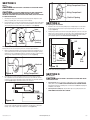
2. From inside the house, insert the inner housing into the outer housing until it is tight against
the wall. Line up three holes at the end of the inner housing with three of the holes on the
outer housing and secure in place with the three included 3/8” screws (Figure 8).
Hole
Figure 8
Inner
Housing
Knockout
Figure 11
Electrical Opening
SECTION 4
Completing the Installation
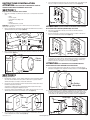
1. Reinstall the fan’s motor bracket by sliding in place and tightening the screws. Rotate
the blower wheel by hand to ensure it spins freely. Now plug the fan motor into the
receptacle (Figure 1).
2. Install grill by positioning over the inner housing and aligning the center hole on the grill
with the hole on the motor bracket. Screw one side of the included grill bolt into the hole
on the motor bracket and the other side into the grill knob and turn to tighten until the
grill is tightly fit against the wall. DO NOT OVER TIGHTEN (Figure 12).
Electrical
Opening
Grill
NOTE: If you removed any of the electrical compartment clearance knockouts on the outer
housing, make sure the electrical opening of the inner housing is aligned with them.
Bolt
3. Pull the electrical wires through the electrical opening of the interior housing. Remove one
of the electrical knockouts of the wiring compartment and run wires through the opening
making sure to leave enough wiring to make the connection to the fan’s receptacle. Secure
wires to wiring compartment with an approved electrical connector (Figure 9).
Motor
Bracket Hole
Electrical
Opening
Grill
Knob
Knockout
Figure 12
3. Restore power and test your installation.
Figure 9
Wiring Compartment
SECTION 5
4. Connect the green or bare ground wire from the house to the ground screw in the
wire compartment. Connect the white wire from the house to the white wire from the
receptacle. Connect the hot (black) wire from the wall switch to the black wire from the
receptacle (Figure 10). Use approved methods for all connections.
Use and Care
CAUTION: MAKE SURE POWER IS SWITCHED OFF AT SERVICE PANEL BEFORE
STARTING INSTALLATION.
1. Cleaning the Grill: Remove grill and use a mild detergent, such as dishwashing liquid,
and dry with a soft cloth. NEVER USE ANY ABRASIVE PADS OR SCOURING POWDERS.
Completely dry grill before reinstalling. Refer to instructions in Section 4 Completing the
Installation, to reinstall grill.
2. Cleaning the Fan Assembly: Wipe all parts with a dry cloth or gently vacuum the fan.
NEVER IMMERSE ELECTRICAL PARTS IN WATER.
Figure 10
5. Insert the wire compartment into the electrical opening of the interior housing and line
up holes of wire compartment and wire compartment cover with holes on the interior
housing. Secure in place using the two included 1/2” screws (Figure 11).
210575005 Rev. C 5-14
www.airkinglimited.com
3 of 8