1
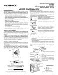
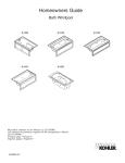
Heater Electrical Cord
Heater (models may vary) T-style (shown)
or In-line (not shown)
Wiring Harness
Bond in accordance with national and local codes.
Open bonding lugs are located at the top of the
junction box.
120/240 VAC
Source
N
L1
L2
Breaker Box
Typical Two-Pole
Circuit Breaker
with GFCI
120 V
120 V
240 V
S/N
Pump Electrical Cord
Junction Box
Control
Typical Wiring Connection for North America
* Connections to be Made
at the Circuit Breaker
*L2
240 V
*L1
No Connection
(Load Neutral)
Wire
Connector
Ground
(Green with
Yellow Stripes)
Blue (L1)
* Line Neutral
(White Curly
Wire)
From
Control
Brown (L2)
* Equipment Ground
Field Wiring
(From Junction Box
to GFCI Breaker)
Neutral Bus
(In Breaker Box)
Wire Connectors
Electrician to provide suitable
strain relief cable.
8. Make Electrical Connections
NOTE: The product model number is printed on a label on the pump side of the whirlpool bath. This
label also identifies the electrical rating of the product. All whirlpools come equipped with a wiring
junction box and are designed to operate between 208 VAC and 240 VAC at either 50 Hz or 60 Hz.
WARNING: Risk of electrical shock. Make sure the power has been disconnected before
performing the following procedures. Refer to the “Important Information” section.
WARNING: Risk of electrical shock. To reduce the risk of electrical shock, connect the pump to a
properly grounded Ground-Fault Circuit-Interrupter (GFCI) or Earth-Leakage Circuit-Breaker
(ELCB). This will provide additional protection against line-to-ground shock hazard. A 208-240 V, 20
A, 50/60 Hz dedicated circuit is required.
IMPORTANT! The load neutral is not used. There should be no connection to the load neutral terminal
on the Ground-Fault Circuit-Interrupter (GFCI) breaker. The green wire with the yellow stripe is the
equipment ground and needs to be connected to the neutral bus in the main circuit breaker box.
The whirlpool bath control and system have been pre-wired at the factory. A licensed electrician
should make a routine service connection to the junction box.
Connect service to the junction box. The junction box contains blue, brown, and green with a yellow
stripe colored wires.
Follow local electrical codes. Bond in accordance with national and local codes.
A wiring harness has been pre-wired at the factory, allowing communication between the keypad,
all features, and the control. No additional wiring is required, but ensure that all wires are securely
fastened.
NOTE: Your wiring harness included an antenna for the optional remote control. Do not alter or damage
this antenna during installation.
Kallista
9
1019455-2-D