1
C
B
C
D
B
A
A
C
B
A
A
Fig. 1
Fig. 3
Fig. 2
E
C
A
Fig. 4
A
B
C
C
C
B
D
A
B
A
Fig. 5
Fig. 6
D
Fig.8
B
A
A
Fig. 10
Fig. 12
Fig. 13
D
J
A
H
B
A
1. BASE DE LA TOUPIE
2. SOUS-BASE
3. MÈCHE DE TOUPIE
4. GUIDE DE GABARIT
5. CONTRE-ÉCROU
1. BASE DEL RAUTER
2. SUB-BASE
3. BROCA
4. GUIA DE PATRON
5. TUERCA INAFLOJABLE
Fig. 11
L
Fig. 9
Fig. 7
1. ROUTER BASE
2. SUB-BASE
3. ROUTER BIT
4. TEMPLET GUIDE
5.LOCKNUT
B
A
SCREW
E
5
D
A
A
B
C
K
C
B
4
1
E
F
Fig. 15
G
Fig. 18
Fig. 17
3
2
Fig. 14
Fig. 16
OPERATION
LUBRICATION
This tool has been lubricated with a sufficient amount of high grade lubricant for the
life of the unit under normal operating conditions. No further lubrication is necessary.
STARTING AND STOPPING THE MOTOR
Before starting the tool, clear the work area of all foreign objects.
Keep a firm grip on the tool to resist starting torque. Two switches (A and B) Fig.
11 turn this tool “ON” and “OFF”. The upper switch (A) will automatically turn
the tool “OFF” if the tool is placed upside down on a surface.
Turn the tool “ON” or “OFF” with lower switch (B), using the thumb of the left
hand while holding the tool.
To avoid injury and/or damage to finished work, always allow the
motor to come to a COMPLETE STOP before putting the tool down.
NOTE: For convenient debris collection, you can attach a shop vac to the
GripVac™ unit by placing the hose on the GripVac handle Fig. 19. See “ACCESSORIES”.
Fig. 19
VARIABLE SPEED CONTROL
This router is equipped with a variable speed control (A) Fig. 12 with an infinite number of speeds
between 10,000 and 23,000 RPM.
Adjust the speed by turning the speed control knob (A).
In low and medium speed operation, the speed control prevents the motor speed
from decreasing. If you expect to hear a speed change and continue to load the motor, you could
damage the motor by overheating. Reduce the depth of cut and/or slow the feed rate to prevent
tool damage.
USING THE TOOL
Always be sure the work is rigidly clamped or otherwise secured before making a cut.
Since the cutter rotates clockwise (when viewing router from top), move the router from left to
right as you stand facing the work. When working on the inside of a templet, move the router in
a clockwise direction. When working on the outside of a templet, move the router in a counterclockwise direction.
Avoid “Climb-Cutting” (cutting in direction opposite that shown in Fig. 13). “ClimbCutting” increases the chance for loss of control resulting in possible injury. When “Climb-Cutting”
is required (backing around a corner), exercise extreme caution to maintain control of router. Make
smaller cuts and remove minimal material with each pass.
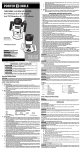
GRIPVAC™ PARTS (FIG. 14)
A.
Router base
B.
Dust port
C.
GripVac handle
D.
Removed handle and screw
E.
Dust deflector
F.
Sub-base with screws
G.
Hex screw (2)
H.
Shoulder washer
J.
Hex nut
INSTALLING THE OPTIONAL GRIPVAC™ (892)
1.
Use a 5/16" hex wrench to loosen the screw in the handle (A) Fig. 15. Remove the handle from
the router base. Store the handle and screw for possible later use.
2.
Remove the plastic plug from the dust port (B) Fig. 14.
3.
Remove the screws (B) Fig. 17 and remove the sub-base (A) Fig. 17.
4.
Align the holes of the GripVac™ handle to the holes of the router base.
5.
Insert a hex screw (G) Fig. 14 through the handle into the hole (K). From inside the base housing,
place a shoulder washer (H) Fig. 14 and a hex nut (J) on the screw. Tighten the nut loosely.
6.
From inside the base housing, insert the second screw (G) Fig. 14 into the hole (11) and screw it
into the threaded hole of the GripVac™ handle.
7.
Turn the router base upside down and place the dust deflector (E) Figs. 14 and 18 into the bottom
of the router base by aligning the three plastic tabs on the deflector with the three recesses in the
base. Align the extended part of the deflector with the GripVac™ handle. The deflector will be
flush with bottom of router base.
8.
Replace the sub-base and the three screws (Fig. 17).
9.
Tighten all hardware securely.
10. Connect any vacuum/dust collection system with a 1" hose to the Grip Vac™ handle (C) Fig. 19.
SOFT START
This router has a “Soft Start” feature designed to minimize startup reaction torque.
TEMPLATE GUIDES (not available for the Model 892)
A wide variety of template guides is available for use in pattern and templet routing operations.
Disconnect the tool from the power source.
To install, insert the templet guide in the center hole of the router base and secure it in place with
a locknut. Before connecting the router to the power source, install the bit, adjust the depth of
cut, and rotate the router chuck by hand to ensure that the bit or collet do not contact the templet
guide.
USING A ROUTER ACCESSORY TABLE
The router can be mounted to a router accessory table (not included). To open the clamp
for motor removal, use a hex wrench in the hole (C), Fig. 17. To adjust cutting depth, use a
hex wtrench in the hole (D) Fig. 17. For instructions on how to mount the router to the router
accessory table, refer to the accessory table instruction manual.
BRUSH INSPECTION (If applicable)
For your continued safety and electrical protection, brush inspection and replacement
on this tool should ONLY be performed by a Porter-Cable Factory Service Center or
a Porter-Cable Authorized Warranty Service Center.
At approximately 100 hours of use, take or send your tool to your nearest PorterCable Factory Service Center or a Porter-Cable Authorized Warranty Service Center
to be thoroughly cleaned and inspected. Have worn parts replaced and lubricated
with fresh lubricant. Have new brushes installed, and test the tool for performance.
Any loss of power before the above maintenance check may indicate the need for immediate servicing
of your tool. DO NOT CONTINUE TO OPERATE TOOL UNDER THIS CONDITION. If proper operating
voltage is present, return your tool to the service station for immediate service.
SERVICE
REPLACEMENT PARTS
Use only identical replacement parts. For a parts list or to order parts, visit our website at servicenet.
porter-cable.com. You can also order parts from your nearest Porter-Cable Factory Service Center or
Porter-Cable Authorized Warranty Service Center. Or, you can call our Customer Care Center at (888)
848-5175.
SERVICE AND REPAIRS
All quality tools will eventually require servicing and/or replacement of parts. For information about
Porter-Cable, its factory service centers or authorized warranty service centers, visit our website at
www.porter-cable.com or call our Customer Care Center at (888) 848-5175. All repairs made by our
service centers are fully guaranteed against defective material and workmanship. We cannot guarantee repairs made or attempted by others.
You can also write to us for information at PORTER-CABLE, 4825 Highway 45 North, Jackson, Tennessee 38305 - Attention: Product Service. Be sure to include all of the information shown on the
nameplate of your tool (model number, type, serial number, etc.).
ACCESSORIES
A complete line of accessories is available from your Porter-Cable Factory Service Center or a Porter-Cable Authorized Warranty Service Center. Please visit our Web Site www.porter-cable.com for a
catalog or for the name of your nearest supplier.
Since accessories other than those offered by Porter-Cable have not been tested with
this product, use of such accessories could be hazardous. For safest operation, only Porter-Cable
recommended accessories should be used with this product.
WARRANTY
To register your tool for warranty service visit our website at www.porter-cable.com.
Porter-Cable warrants its Professional Power Tools for a period of one year from the date of original
purchase. We will repair or replace at our option, any part or parts of the product and accessories
covered under this warranty which, after examination, proves to be defective in workmanship or
material during the warranty period. For repair or replacement return the complete tool or accessory,
transportation prepaid, to your nearest Porter-Cable Service Center or Authorized Service Station. Proof
of purchase may be required. This warranty does not apply to repair or replacement required due to
misuse, abuse, normal wear and tear or repairs attempted or made by other than our Service Centers or
Authorized Service Stations.
ANY IMPLIED WARRANTY, INCLUDING THE IMPLIED WARRANTIES OF MERCHANTABILITY AND
FITNESS FOR A PARTICULAR PURPOSE, WILL LAST ONLY FOR ONE (1) YEAR FROM THE DATE
OF PURCHASE.
To obtain information on warranty performance please write to: PORTER-CABLE, 4825 Highway
45 North, Jackson, Tennessee 38305; Attention: Product Service. THE FOREGOING OBLIGATION
IS PORTER-CABLE’S SOLE LIABILITY UNDER THIS OR ANY IMPLIED WARRANTY AND
UNDER NO CIRCUMSTANCES SHALL PORTER-CABLE BE LIABLE FOR ANY INCIDENTAL OR
CONSEQUENTIAL DAMAGES. Some states do not allow limitations on how long an implied warranty
lasts or the exclusion or limitation of incidental or consequential damages, so the above limitation or
exclusion may not apply to you.
This warranty gives you specific legal rights and you may also have other legal rights which vary from
state to state.
WARNING LABEL REPLACEMENT
If your warning labels become illegible or are missing, call (888) 848-5175 for a free replacement.
TROUBLESHOOTING
For assistance with your tool, visit our website at www.porter-cable.com for a list of service centers, or
call the Porter-Cable Customer Care Center at (888) 848-5175.
Model 890
Heavy Duty Router
MAINTENANCE
KEEP TOOL CLEAN
Periodically blow out all air passages with dry compressed air. All plastic parts should be cleaned with a
soft damp cloth. NEVER use solvents to clean plastic parts. They could possibly dissolve or otherwise
damage the material.
Wear ANSI Z87.1 safety glasses while using compressed air.
TYPE 1
Ser No.
TO REDUCE THE RISK
OF INJURY, USER MUST READ AND
UNDERSTAND INSTRUCTION MANUAL.
AVERTISSEMENT
lire le guide.
FAILURE TO START
Should your tool fail to start, check to make sure the prongs on the cord plug are making good contact in
the outlet. Also, check for blown fuses or open circuit breakers in the line.
À Titre Préventif,
PORTER-CABLE
JACKSON, TN 38305 U.S.A.
MADE IN MEXICO
Make sure dust
port is completely
covered when
operating tool.