1
SA 200
GB
Check and calibration of MPU-units with detector types MPD, MP-DS, MP-DR and MP-DK
Check and calibration of detector types GD230/24,
GS230/24, GR230/24, GK230/24 and GSR230/24
To check and calibrate the equipment you need an SA200 –
service-adapter, connected to a multimeter.
To check and calibrate the detector you need an SA200 service adapter, connected to a multimeter.
Important
The MPU-unit and the detectors have to be power supplied at
least 1 hour before any adjustment is made and without any
airflow influence during the test.
1. Check power supply.
GD/GS/GR230 - supply 230VAC
GD/GS/GR24 - supply 12-24VAC or DC
Check power supply.
If no UPS - supply 230VAC
With UPS - supply 24VDC
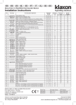
2. Connect the SA200-serviceadapter to the test terminal.
Turn the switch to check right setting/value.
Start to check the 5 VDC circuit, turn switch to "SUPPLY 5V".
The value shall be 5 V +-0,15V.
Procedure per channel:
1. Connect the SA200-service adapter to the test terminal
on the control board (one per channel).
Turn the switch to check right setting/value.
Start to check the 5 VDC circuits, turn switch to “SUPPLY 5V”.
The value shall be 5 V +-0,15V.
3. How to check zero point, "offset".
(Offset = GV-value in clean air) Turn switch to "OFFSET" and
read the value. The offset-value shall be approx. 0,2-0,5V DC,
depending on gas type. The voltage shall increase of gas
influence.
Adjusting the offset-value is made by the GV-pot on the
terminal board. The detector has to be power supplied at least 1
hour before any adjustment is made and without any airflow
influence during the test.
IMPORTANT! Adjusting offset value has to be done in clean
air.
2. Check zero point, “offset”.
(Offset = GV-value in clean air). Turn switch to “OFFSET” and
read the value. The offset-value shall be approximately 0.2 –
0.5 VDC, depending on gas type. The voltage shall increase of
gas influence. Adjusting the offset-value is made by the GVpotentiometers on the detectors.
IMPORTANT! Adjusting offset-value has to be done in
clean air.
4. Check and changing of alarm levels.
At the control board there are three potentiometers to adjust set
points for alarm "A","B" and "C".
How to change the alarm levels.
- Connect the instrument and turn switch to "ALARM A", then
adjust the potentiometer "A" until the new value is showed on
display.
Repeat the procedure for alarm level B and C.
For information about set points and ALARM-levels for different
types of gases, please contact us.
3. Check and changing of alarm levels.
At the control board there are three potentiometers to adjust
setpoints for alarm “A”,”B” and “C”.
How to change the alarm levels.
Connect the instrument and turn switch to “ALARM A”, then
adjust the potentiometer “A” until the new value is shown on
display.
Repeat the procedure for alarm level B and C.
For information about set points and ALARM-levels for different
types of gases, please contact us.
Troubleshooting.
Troubleshooting.
Detector gives no alarm on gas influence?
- Check that offset (GV-value) will increase at gas influence,
voltage must be higher than set point value to effect an alarm.
- Check that there is no time delay chosen at the DIP-switch.
- Check that "Service mode" is not chosen.
Detector gives no alarm on gas influence?
- Check that offset (GV-value) will increase at gas influence,
voltage must be higher than set point value to effect an alarm.
- Check that there is no time delay chosen at the DIP-switch.
- Check that "Service mode" is not chosen on the channel.
Constant alarm from detector?
- Check the offset (GV-value) as above and that there is no gas
in the area.
- Check that there are no other gases, solvents or other
vapours (smells) which can disturb and give a false alarm.
- If GV-value is too high (more than any alarm level) move the
detector to another area without gas and re-calibrate the offset
(GV-value) once again as above.
Constant alarm from detector?
- Check the offset (GV-value) as above and that there is no gas
in the area.
- Check that there are no other gases, solvents or other
vapours (smells) which can disturb and give a false alarm.
- If GV-value is too high (more than any alarm levels) move the
detector to another area without gas and re-calibrate the offset
(GV-value) once again as above.
Constant Fault Alarm?
- The detector has a built-in fail-safe circuit, meaning that if the
gas sensor (gas sensing element) breaks down, the unit will
indicate fault alarm. The same thing will happen if the offset
(GV-value) is too low < ~0,1V.
- If that happens, make a new offset calibration as above, and
increase the offset to 0,2-0,5V.
Constant Fault Alarm?
- The detector has a built in fail-safe circuit, meaning that if the
gas sensor (gas sensing element) breaks down, the unit will
indicate fault alarm.
The same thing will happen if the offset (GV-value) is too low <
~0,1V.
- If that happens, make a new offset calibration as above, and
increase the offset to 0.2-0.5V.
IS SA200 0711.doc
5