1
f
Il
70
1
059
1
~
1
]D
rnE1.I~'rr- - -....
ÉQUIPEMENT ÉLECTRIQUE
ELECTRICAL EQUIPMENT
GammeS
BRange
12 VOLTS
Classement/Reliure
Classification/Binding
OrdnungszahllBand
Klasseringen/Boekbinder
Clasificaci6n/Encuadernaci6n
Classificaçâo/Capa
Classifica/Fascicolo
Inddeling/Bind
M.R.tOt .,.. 70.0
M.R.20t
RENAULT
Vehicules Industriels 11/91 • Imprimé en France· Atelier M. MICHAUD et FILS (1300)
11
5000634382
[I] [70
2
1
059
COMPOSITION DU CHAPITRE MÉTHODE RÉPARATION
Pour être à jour à la date de 11/1991
votre CMR 70 059 doit contenir les éléments suivants:
BREAKDOWN OF REPAIR METHOD CHAPTERS
To be up to date as at 11/1991
your CMR 70 059 must contain the fol/owing elements :
FASCICULES
PAGES
DÉSIGNATION
DESCRITPION
PAGES
PAGES
A
Équipement électrique modèle 1982
Electrical eqUipment 1982 model
A1-A12
8
Équipement électrique modèle 1988
Electrical equipment 1988 model
81-84
C
Équipement électrique modèle 1991
Electrical equipment 1991 model
C1-Ca
© Renault Véhicnles Industriels· 1991
ÉDITION
ISSUE
N° ARTICLE
ARTICLE N°
11/1991
5000634382
1(")
_'_1170
059
TABLE DES MATIÈRES
CONTENTS
Pages
A1-A12
INSTALLATION ÉLECTRIQUE MODÈLE 1982
Lecture du schéma
.
A1
Schéma de principe
..
A2
Légende des appareils ..................••......•......•........ A3- A4
AS
Schéma général....••....•...............•••••.••........••.......
AG
Tableau des ampoules•...........•..•.•••.•••••••..............
Batterie d'accumulateurs
.
A7
Platine de servitude .•...................•••••..••...............·
A7
Fusibles
.
A8
. A9-A10
Tableau de bord
A11
Éclairage
.
A12
Préchauffage
.
1982 MODEL ELECTRICAL INSTALLATION
Reading the diagram
Schematic diagram
Equipment key
General diagram
Table of lamps
Batteries
Control panel
Fuses
Instrument panel
Lighting
Preheating
INSTALLATION ÉLECTRIQUE MODÈLE 1988
Légende des schémas
Schéma de principe
Affectation des fusibles
.
..
.
B4
1988 MODEL ELECTRICAL INSTALLA nON
Kéy to diagrams
Schematic diagram
Fuses (assignementJ
INSTALLATION ÉLECTRIQUE MODÈLE 1991
Schémas de principe
Alimentation disponible
Affectation des fusibles
..
.
.
C1-CG
C2-CS
CS
CG
1991 MODEL ELECTRICAL INSTAUAnON
Schematic diagrams
Available power supply
Fuses (assignmentJ
Renault Véhicules Industriels· 11191
B1- B4
B1
B2/B3
3
059
Al
ÉQUIPEMENT ÉLECTRIQUE
ELECTRICAL EQUIPMENT VERSION
LECTURE DU SCHÉMA
READING THE DIAGRAM
REPËRAGE DES CAB LES
JAl/RE IDENTIF/CA TlON
Chaque fil est identifié par l'abréviation de sa couleur. Ce
repérage peut être complété par un embout de couleur.
Exemple:
MC = fil marron avec embout cristal.
Each wire is identified by the abbreviation of its c%r. This
identification system can be comp/eted by a c%red s/eeve.
Examp/e:
MC = brown wire with c%rless s/eeve.
ABRÉVIATION DES COULEURS
COLOUR ABBREVIATIONS
NOIR
MARRON
ROUGE
ORANGE
JAUNE
VERT
BLEU
VIOLET
GRIS
BLANC
BEIGE
CRISTAL
BLACK
=N
BROWN
=M
RED
=R
ORANGE = Or
YELLOW =J
GREEN
Ve
BLUE
= Bu
PURPLE = Vi
GREY
=G
WHITE
= Be
BEIGE
= Bj
CRYSTAL = C
=N
=M
=
=
=
=
=
=
R
Or
J
Ve
Bu
Vi
G
Bc
Bj
C
CROSS SECTIONS OF WIRES
SECTION DES CABLES
Colour
Couleur
)(
III
hi
Il
II
Marron
Vert
Jaune
Bleu
Rouge
Orange
Z
j
1
)(
00
•
II
75 mm 2
50mm 2
25mm 2
14 mm 2
7mm 2
5mm 2
3mm 2
2mm 2
1 mm 2
0,6 mm 2
Brown
Green
Yellow
Blue
Red
Orange
REPI:RAGE DES APPAREILS
EaUIPMENT MAR KING
Chaque appareil représenté dans le schéma est accompagné
d'un numéro.
La lecture s'effectue de gauche à droite, vue de la place du
conducteur.
Les appareils ouvrant ou fermant un circuit, comportent un
schéma interne les représentant à leur position de repos.
Eaeh piece of equipment shown on the diagram is identified by a number.
The numbers should be read from left to right, seen from
the Driver's seat.
The switching gears bear on internai diagram showing
them at rest position.
REPI:RAGE DES CIRCUITS
SYSTEM MAR KING
Des connecteurs multibroches, munis de détrompteurs,
relient tous les circuits. Certains de ces connecteurs portent
aussi une pastille de couleur. Leur position relative sur le
schéma et la concordance des repères permettent également
la remise en place correcte en cas de débranchement de
plusieurs de ces connecteurs.
A chaque entrée de câble dans un faisceau, figure le numéro
repère de l'appareil auquel est relié ce conducteur à son
autre extrémité.
Les faisceaux étant uniformisés pour plusieurs types de
véhicules, certains conducteurs destinés à des options peu·
vent rester en attente dans une boîte de dérivations, sur un
connecteur ou sur un emplacement d'appareil muni d'un
obturateur.
Ail the systems are connected through multi-pin connec·
tors fitted with locators. Some of those connectors also
bear a couloured pellet. Their relative position on the dia·
gram and the index marks also enable the correctpositioning
in cases where matching several of these connectors have
been disconnected.
Each wire entry into a harness bears the item number of
the equipment to which the other end of the wire is con·
nected to.
As the harnesses have been standardized for several types
of vehicles, some wires designed for optional equipment
may remain in a dividing box, on a connector or on an
equipment location fitted with a blanking plug, plending
connection.
NOTA: Le repérage des appareils est identique sur
tous les schémas (légende pages A3-A4).
NOTE: On al/ diagrams (/egend, pages A3-A4),
equipment identification is identical.
Renault Véhicules Industriels· 11/91
f
A2
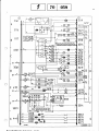
SCHEMA DE PRINCIPE B70
FUNCTIONAL DIAGRAM B70
G
Il-S
56
059
70
1 [
-------'
1+
11
/ ..........
'-J
56
~
< > - - - - - - - - - - . . . . : : G - - - t } l € )--_ _---:..;N:...-._ _4
7
1
q
.,
14
-=8:..::.c
b--
N
54
13
1
N.O
f-B-~-----~----~
~
~ L-- 50 ja785-· 30 86
1
---o-
53
1
1
_..,.+
_.~-------------i
,...-..:...:N=.8-,,-c
R
N.O
N.R
~
p
Rr-------
55
~
J
~D
Ve
è=l
'l!:1/r<-----''''------'lr'''~-:--------___i49
M
w.
41
F
s _
I ....*'-;lII:-----'M-'--oO----!---------i
t-----LH.....
;-'6-.::l:~~
v;
N
~~
'-
12
<il" À-~ ---
: IS
~---;:::~~~---------l
57_70.72C
32
58
64.6RA
72.73 A
40
40
16
' .. _ '
.-:.J•• :\
R
::J...
1
r..L
N
<=
lr:;;
-'"
.x
f\v \
1
@ .5A
.. h
R
J
@8A
Be:
3 11 ~ 5A
00 00
'-..':1
5
J
:f
1~1~[=A=- __--+_----=S:;....--___1....,iX)--.=..J- - - - - 1
:
1"
='
3:sA:
.c"A
VI!
J
Ve
1
l
Q::::J
,,_
: r--':
~ --~l------_
:__ .. -- - __ ..
3
:
:Sc;~!
5
:;~~I~:~.-~ --_1- ----------------- -- ------ ~---'~~-------------------:::
•
t------ëë----c;------------------t::!·-V!--(::•. ------------
BJ~
2.60.64.66A
36
39
2
8
8
9
18A
80
66.67E
47
~
'.:la
53
53b
~'?>ou.r31b
l--=
rcv-V==R=-
6
111
...!R!...(,l-.;..a--:N
..:..-
1
Renault Véhicules Industriels· 11191
10_72.738
8.63.72.73 A
67.68.700
2
5_~_,-_"!""~---.4~.K~-_:"N;-----------;
--- ~- -- --':=~ -}- - ...- - --
29
~-:jB~U. .-:±f_*~;;lT====±:~~~~====1
i [~i~~t= =~ ~=~ --------1"~~i
--- -- -L - -13- -- --- --: -- ----- -----4--.
. __ . . c:
.. _.. ---1
,,--
0000
RI'
l
<l)1DA
:J
1_64_668
OOOOJ
OOOOJ
-t====~Lr~;1rï~=~===~iiIlNr:i..-. -_-....:OO;~O();6======4
. _J.
81
iM
: J
2
@ 5A
R...)
, ri
L.::::.J~
@5A
43
45
X
ï----------I;F-~-~l<:-=;~)f:i'=,-;I -_-~ ~- =- -·-·-=-·-·-·-=- J-;i-;-+: .:_~:._~.s~.~---:.:'<J-~~-,--:------_-----j
~
188
46
62
N:
'ô
C
~:
18C
44
1
@5A --G1I71...---------'s...........~~,...u.+: -~--......
------t
58
30
5
G - ----Ve
8c--
,:li.
52
51
50
____
4
'----f_1 [io
i
LEGENDE DES APPAREILS
Feu cl ignotant avant gauche
Projecteur et veilleuse gauche
Masse
Lave-vitre
Niveau liquide frein
Moteur essuie-glace
Masse
Projecteur et veilleuse droit
Avertisseur
Feu clignotant avant droit
Accumulateurs 12 V 100 A/h
Contact de stop
Thermocontact pour ventilateur
Relais préchauffage automatique
Fiche faisceau prise de mouvement*
Fiche information compte-tours
Relais ventilateur débrayable
Platine de servitude
A.
Relais anti-brouillard avant*
B.
Centrale clignotante
C.
Relais aérotherme
Connecteurs sur platine de servitudes
Fiches d'alimentation
Masse sur colonne de direction
Commande feu de brouillard arrière
Commande signal de détresse
Fiche faisceau frein à main
Frein à main
Sans affectation
Connecteur sur tableau de bord
Platine sur tableau de bord
A.
Compte-tours*
C.
Indicateur niveau carburant
D.
Indicateur température eau
F.
Témoin préchauffage
G.
Témoin frein à main
H.
Témoin alerte eau
J.
Témoin clignotant remorque*
K.
Témoin projecteurs de route
L.
Témoin clignotant porteur
M.
Témoin signal de détresse
N.
Témoin disponible
P.
Témoin circuit de charge
O.
Témoin disponible
R.
Témoin prise de mouvemel";t*
S.
Témoin disponible
T.
Témoin veilleuses, éclairage tableau de bord
V.
Témoin disponible
W.
Témoin alerte huile et alarme générale
XV. Témoin disponible
Controlographe
Aérotherme
Commande de démarrage
Fiche de sécurité démarrage
Commande indicateur de direction
Commande éclairage avertisseur
Commande essuie-vitre, lave-vitre
Plafonnier cabine
Allume-eigare
Contact sur prise de mouvement
Transmetteur température eau
Thermo-contact eau
Thermo-eontact huile
Electro-vanne arrêt moteur
Bougie de préchauffage
Ventilateur débrayable
Alternateur
Renault Véhicules Industriels· 11191
059
A3
KEY Tü THE EQUIPMENT
1
2
3
4
5
6
7
8
9
10
11
12
13
14
15
16
17
18
19 --.. 26
27
28
29
30
31
32
33-34
35
36
39
40
41
42
43
44
45
46
47
48
49
50
51
52
53
54
55
Front lefthand flasher
Lefthand high beam-Iow beam
Ground
Windshield washer
Brake fluid level
Windshield wiper motor
Ground
Righthand high beam-Iow beam
Horn
Front righthand flasher
12 V 100 A/h accumulators
Stop switch
Fan thermal switch
Au toma tic preheating relay
Power takeoff harness connector
Rev counter signal connector
Releasable fan relay
Ancillary panel *
A.
Front fog light relay*
B.
Flasher unit
C.
Heat relay
Connectors on ancillary panel
Supply connectors
Steering column ground
Rear fog light control
Hazard flasher control
Handbrake harness connector
Handbrake
Not allocated
Instrument panel connector
Panel on instrument panel
A.
Revcounter*
C.
Fuellevel indicator
D.
Water temperature indicator
F.
Preheating indicator
G.
Handbrake indicator
H.
Water warning light
J.
Trailer flasher indicator*
K.
High beam light indicator
L.
Hanlage drawbar flasher indicator
M.
Hazard flasher indicator
N.
Indicator available
P.
Charging circuit indicator
Q.
Available indicator
R.
PTO indicator*
S.
Indicator available
T.
Dimmer, instrumentpanellighting indicator
V.
Available indicator
li1/.
Oil and general alarm indicator
XY. Available indicators
Tachograph
Airheater
Starting control
Starting safety connector
Direction indicator control
Lighting - horn control
Windshield washer - wiper control
Cab roof /ight
Cigar /ighter
PTOcontact
Water temperature transmitter
Water thermal switch
Oil thermal switch
Engine shutdown solenoid valve
Preheating plug
Releasable fan
Alternator
A4
f
Démarreur
Contact sur marche arrière
Transmetteur niveau carburant
Sans affectation
Feu de gabarit gauche*
Connecteur feux de gabarit*
Plafonnier arrière (bourgon)
Feu de gabarit droit*
Sur véhicule châssis:
A.
Feu stop et feu rouge gauche
B.
Feu clignotant gauche
Connecteur feux arrière gauche (sur fourgon)
Sur fourgon :
A.
Feu stop et feu rouge gauche
B.
Feu clignotant gauche
E.
Feu de brouillard arrière
Sur véhicule châssis:
D.
Eclaireur de plaque gauche
E.
Feu de brouillard arrière
Eclaireur de plaque (fourgon)
Connecteur sur fourgon
Sur véhicule châssis:
C.
Feu de recul
D.
Eclaireur de plaque
Connecteur feu arrière droit
Sur fourgon :
A.
Feu stop et feu rouge droit
B.
Feu clignotant droit
C.
Feu de recul
Sur véhicule châssis:
A.
Feu stop et feu rouge droit
B.
Feu clignotant droit
Projecteurs anti·brouillard avant
Commande projecteurs anti-brouillard
Les repères à partir de 80 figurent
uniquement sur le schéma de
principe page A2.
Renault Véhicules Industriels· 11/91
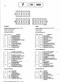
Il 70
56
57
58
59
60
61
62
63
64
65
66
67
68
69
70
71
72
73
80
81
059
Starter
Reverse contact
Fuellevel transmitter
Not allocated
Lefthand side light *
Side 1ight connector *
Reer roof light (van)
Righthand side light
On vehic/e chassis:
A.
Stoplight and lefthand red light
B.
Lefthand flasher
Lefthand rear light connector (on van)
On van:
A.
Stop and lefthand red /ight
B.
Lefthand flasher
E.
Rear fog light
On vehicle chassis :
D.
Lefthand plate /ighter
E.
Rear fog /ight
Plate lighter (van)
Connector on van
On vehicle chassis
C.
Reversing /ight
D.
Plate light
Rear righthand light connector
On van:
A.
Righthand stop and red /ight
B.
Righthand flasher
C.
Reversing light
On vehicle chassis :
A.
Righthand stop and red lights
B.
Righthand flasher
Front fog lights
Fog light control
Item 80 and above on diagram
of page A2 only.
~f---,1 [Jo
1_0_59------'
TABLEAU DES LAMPES 12 VOLTS
Affectation
Eclairage tableau de bord et tous témoins
Eclairage commandes chauffage ventilation
Eclairage allume-cigares
Feux de position avant
Feux de position arrière et stop
Feux de route et croisement
Puissance
1,2 W
4W
1,2 W
4W
21/5 W
45/40 W
*Feux de route iode
60W
*Anti-brouillard avant
55W
Feux de brouillard arrière
21 W
Feux clignotants avant et arrière
21 W
Feux clignotants latéraux
3W
Feux d'encombrement
5W
Feux de recul
21 W
Eclairage plaque de police
4W
Plafonniers
7W
TABLE OF 12 VOLT BULBS
Allocation
Instrument panellighting and ail indicators
Heating-eooling controllighting
Cigar lighter lighting
Front side lights
Rear side lights and stoplight
High·low beam
Halogen lights
Front anti·fogJight
Rear fog light
Front and rear flashers
Side flashing lights
Marker lights
Reversing light
Licence plate lighting
Rooflights
DIt Véhicnles Industriels· 11/91
Wattage
1.2W
4W
1.2W
4W
21/5W
45/40W
50W
55W
21 W
21 W
3W
5W
21W
4W
7W
A6
....
Rena
ITJI70
BATTERIES
Les batteries de ces véhicules sont fixées
par le talon.
Deux types de batteries sont livrés par
le M.P.R.:
Bac couleur noire: elles sont conçues
pour être fixées par étrier et tirants.
Il est interdit de fixer ces batteries
par le talon (risque de rupture).
Bac couleur bleue: elles sont prévues
pour être fixées par le talon et peuvent, en dépannage, être fixées par
étrier et tirants.
The batteries on these vehicles are
attached via a « heel !!.
M.P.R. delivers two types of battery :
- Black battery : designed for attach·
ment using a yoke and turnbuckles.
These batteries must not be attached
by the heel (risk of damage).
- Blue battery : these are designed
for attachment by the heel, and as a
repair, ean be attached by yokes
and turnbuekles.
••
Une tension inférieure nécessite une
recharge de la batterie.
Pes~r l'électrolyte. Effectuer une comparaison de densité entre les éléments.
La différence entre élément ne doit pas
dépasser le poids spécifique de 0,030.
Afin de connaître l'état exact .de la
batterie, utiliser l'appareil herrnologué
MOTOROLA 1 BT-1181 W.
"t
t· ,.
A7
BATTERIE D'ACCUMULATEURS
Battery test
Oëmtflnê'dèS~tiâttèrÎes
"
059
Précautions à prendre
Recharger les batteries au 1/lOe de leur
capacité pendant 10 heures.
Ne jamais rajouter de l'électrolyte mais
de l'eau distillée.
Ne jamais vidanger une batterie de son
électrolyte.
Veiller à ce que les éléments de la batterie soient toujours recouverts par "électr
/La résistance au froid est fonction de
l'état de ç.harge. Une batterie chargée
à I!l'densité de :
1,115 résiste à - 7 oC environ
1,160 résiste à - 15 oC environ
1,210 résiste à - 30 oC environ
1,250 résiste à - 45 oC environ
en outre, la capacité disponible d'une
batterie correctement chargée est de :
100 % à 27 oC
66 % à O°C
41 % à - 20 oC
34
Measure the voltageacross the terminais.
This must be equal to or greater than
12.5 V. A lower voltage will cali for
replacement of the battery. Weight
the electrolyte. Compare the cell specifie gravities. The difference between
cells must not exeeed the specifie weight
of 0.030.
To check the exact condition of the
battery, use the MOTOROLA 1 BT·
1181 W device.
Precautions to be taken
Charge the batteries to 1/10 of their
capacity for 10 hours.
Never add electrolyte, but simply dis·
tilled water.
Never drain the electrolyte from a battery.
Make sure that the battery cells are
always covered by the electrolyte.
ALWA YS DISCONNECT THE NEGA·
TIVE CABLE FIRST.
Cold resistance is a function of charging
condition.
A charged battery to specifie gravity :
. 1.115 withstands - 7 oC approx.
1.160 withstands - 15 oC approx.
. 1.210 withstands - 30 oC approx.
- 1.250 withstands - 45°C approx.
in addition, the available capacity of
the correctly charged battery is :
100 %at 27°C
66%atO°C
41 %at-20°C
ANCILLARY PANEL
Pl,.ATINE DE SERVITUDE
REMOVAL
DEPOSE
- Disconnect the battery.
- Remove both screws (A) to obtain
access to the panel.
- Disconnect the connection blocks,
which are of different colors (the
coupling color is indicated by a disk
on the panel).
Disconnectpower wires (B).
- Extract the panel,
Débrancher la batterie.
Déposer les' 2. vis (A) afin d'accéder
à la platine.
Débrancher les blocs raccords qui
sont de couleurs différentes (sur la
platine une pastille indique la couleur
du raccord).
Débrancher les fils d'alimentation (B).
Sortir la platine.
PARTICULARITES DE LA REPOSE
Respecter la position des blocs raccord.
Renault Véhicules Industriels· 11/91
INSTRUCTIONS FOR
INSTALLATION
Respect the position of the connection
blocks.
.
ITJI70
A8
-____v
--,.;.()
1
Il
Il
11
11
1
1
1
Il
1
..
g
'f\D-'"
- - --r-- Il0 .. 0
- ---0 !rl'<'r
- --.
059
.
0
~
Il
Il
0
Ile
Il
Il
Il
r-
110
r
1
rf"('~
N' 0
Il
0
~:Jmm]
1
80 481A
36
AFFECTATION DES FUSIBLES
Affectation
-
-
-
••••••••••
Assignment
A
Feu de croisement droit,
Feu de brouillard arrière ..........
2. - Feu de croisement gauche .........
3. - Feu de route gauche · ............
Feu de route droit · .............
4.
5. - Essuie-vitre, plafonniers ...........
6. - Aérotherme
· .............
7. - Anti-brouillard avant . . . . . . . . . . . . .
8. - Prise de mouvement · ............
9. - Allume-cigare, montre, contrôlographe
10. - Disponible
· .............
11. - Feu stop, feu de recul, voyants ......
12. - Centrale clignotante · ............
13. - Feu de position gauche, éclairage des
instruments . . . . . . . . . . . . . . . . . . .
14. - Feu de position droit, éclaireur de
plaque ........... " .........
15. - Disponible . . . . . . . . . . . . . . . . . . . .
Rechange
16.17.
1.
ASSIGNMENT OF FUSES
o'
••••••••
Renault Véhicules IndustrielK • 11/A1
1.
5
5
5
5
10
16
10
10
8
10
5
5
5
5
5
5
A
-
Righthand high beam,
Rearfog . .............. , .....
2. - Lefthand low beam ..............
3. - Lefthand side light · ..............
4. - Righthand side light .............
5. - Windshield wiper, roof lights ........
. . •• o' • • • • • • • , ••
6. - Airheater
7. - Front fog light . . . . . . . . . . . . . . . ..
8. - Power takeoff . " .......... " ...
9. - Cigar lighter, clock, tachograph ......
10. - Available
• ••• , ••• , o' • • • • •
11. - Stoplight, reversing 1ight, indicator 1ights
12. - Flasher unit. . . . . . . . . . . . . . . . . . .
13. - Lefthand position light,
instrument lighting · ........ " ...
14. - Righthand position light,
number plate light · .............
15. - Available . . . . . . . . . . . . . . . . . . . . .
16.17. - Spare
•
•
o'
....................
5
5
5
5
10
16
10
10
8
10
5
5
5
5
5
5
,
_f----JI
1
70 J_O_5_9_
TABLEAU DE BORD
INSTRUMENT PANEL
DEPOSE
REMOVAL
Débrancher la batterie.
Débrancher le câble de tachymètre
en tirant par en dessous.
Par en dessous pousser sur le haut de
la platine, voyants-contrôle, puis tirer
de l'avant.
Débrancher les 3 connecteurs (repérer
les couleurs).
Débrancher les interrupteurs.
Déposer les 2 vis de fixation des
pattes avant (A).
Sortir l'agrafe placée sur la patte
centrale arrière.
Sortir l'ensemble en faisant pression
sur les 3 pattes arrière.
80-499
37
A9
- Disconnect the battery.
- Disconnect the tachometer cable,
pulling if from underneath.
From underneath, push against the
top of the panel, then pull from the
front.
Disconnect the three connectors
(mark the colors).
Disconnect the switches.
Remove bath attaching screws from
front lugs (A).
Extract the fastener located on the
rear center lug.
- Remove the assembly by pressing
against the 3 rear lugs.
REMPLACEMENT DU
CIRCUIT IMPRIMI:
REPLACEMENT OF
PRINTED CIRCUIT
Dévisser les écrous de fixation et de
branchement des récepteurs.
Enlever et remplacer le circuit imprimé.
Unscrew the receiver attaching and con·
necting nuts.
Remove the printed circuit.
TeMOINS ET INDICATEURS
DE FONCTIONNEMENT
INDICATOR LIGHTS
Chaque témoin ou indicateur est ali·
menté après contact par le circuit imprimé du tableau de bord.
Instruments à aiguille:
ils indiquent la température eau, le
niveau du carburant.
Témoins de contrôle:
une figurine sur chaque témoin
indique sa fonction.
Compte-tours (suivant option) :
il indique la vitesse de rotation du
moteur à partir:
sur le type B70 équipé du moteur
diesel (8140), de la fréquence de
l'alternateur (fil saumon),
Renault Véhicules Industriels· 11191
80_500
38
Each indicator light is supplied from
the instrument panel printed circuit.
- Meter type instruments:
these indicate water temperature and
fuellevel.
Indicator Iights :
an illustration on each indicator
shows its function.
Rev counter (optional) :
indicates engine speed from :
- on type 870, equipped with diesel
engine (8140), alternator frequency
(Salmon wire),
AlO
_'_1170
+
w
o
059
51
80_ 501.
39
FONCTIONNEMENT DES VOYANTS
INOICATOR LIGHT OPERATION
Fonction testeur de voyants:
A l'arrêt, contact coupé, les voyants
sont éteints.
A l'arrêt, contact mis, tous les voyants
« alerte » s'allument par l'intermédiaire du mano-contact huile (51), la
fonction testeur de voyants est assurée.
Le moteur démarre, le contact passe
en position ouvert tous les voyants
« alerte» s'éteignent.
Indicator light tester function :
- Stopped, contact switched off, indicator Iights extinguished.
- Stopped, contact switched on, ail
« alarm Il lights come on via oil
pressure switch (51), the indicator
Iight tester function is provided.
Engine started, the contact changes
to the open position ,. ail « alarm Il
Iights go out.
Fonction alarme générale:
Lorsque le thermo-contact eau (50) ou
le contact sur maître-cylindre de frein
(5) passe en position fermée (indiquant
un incident), le voyant qui correspond
ainsi que le voyant alarme (W) s'allument, mais les témoins non concernés
par cet incident restent éteints.
Les diodes 05, 06, 07, 08 permettent l'allumage du voyant alarme
(W) lorsqu'un des autres circuits
est fermé (incident).
Les diodes 01, 02, 03, 04 permettent de tester les voyants d'alerte
lorsque le circuit du voyant (W)
est fermé (moteur arrêté).
W
: voyant alerte pression huile
H
: voyant alerte eau
Y
: voyant alerte liquide de frein
X - Y : voyants disponibles
General alarm function
When the water thermal contact (50)
or the brake master cylinder (5) closes
(indicating an incident), the corresponding indicator, together with the alarm
Iight (W) Iight~· the indicators not involved in the incident remain extinguished.
- Diodes D5, D6, Dl and DB enable
Iighting of the alarm indicator (W)
when one of the other circuits is
closes (incident).
- Diodes Dt, D2, D3 and D4 are used
to test the alert Iights when the indicator light circuit (W) is closed
(engine stopped).
Renault Véhicules Industriels· 11/91
W
H
y
X-Y
: oil pressure warning light
: water alarm light
: brake f1uid alarm light
: available
059
A 11
ECLAIRAGE COMMUTATEUR
L1GHTING SWITCH
DEPOSE
REMOVAL
Disconnect the battery.
Remove the 6 attaching screws on
the casing under the steering wheel.
Disconnect the crystal connectar
(48) trom the ancillary panel.
Remove the switch attaching screws.
Débrancher la batterie.
Déposer les 6 vis de fixation du carter
sous volant.
- Déconnecter sur la platine de servitudes le connecteur cristal (48).
Déposer les vis de fixation de l'appareil.
REPOSE
INSTALLATION
80.492
Opérer en sens inverse de la dépose.
Reverse the removal procedure.
40
Fonction
Cou!. Rep. Rep.
des Icom- Iconfils mut. nect.
alimentation
commutateur
rouge
alimentation
lanternes
jaune
alimentation projecteurs de croisement beige
alimentation projecgris
teurs de route
alimentation
avertisseur
blanc
1
6
2
5
3
4
4
8
5
7
Function
Switch supp/y
Light supp/y
Low beam supply
High beam supply
Warning supply
Wire Mark Mark
on
color on
switch con.
red
yel·
low
beige
grey
white
1
6
2
3
4
4
5
5
8
7
PROJECTEURS
HEAOLIGHTS
L'optique est positionné par 2 logements ouverts (A) côté extérieur et un
logement de centrage (B) en bas, côté
radiateur. La fixation est assurée par une
tige de verrouillage (C).
The optical system is set by means of
two open housings (A) on the outside,
and a centering housing (B) at the
bottom on the radiator side. The
attachment is made by means of a
locking rad (C).
To remove the optical system, turn
the /ocking rod (C) through one-quarter
of a turn, push the optical system forward, then s/ide it towards the radiator
and remove, after having disconnected
the head/ight connector (0) and light
connector (E).
Pour déposer l'optique, effectuer un
quart de tour à la tige du verrouillage
(C), pousser l'optique vers l'avant puis
faire glisser l'optique vers le radiateur,
le sortir après avoir débranché le con·
necteur projecteur (0), la lanterne (EL
BO.510
REPOSE
42
Opérer en sens inverse puis régler les
optiques.
INSTALLATION
=;=
Reverse the removal procedure, then
adjust the optical assemb/ies.
REGLAGE
AOJUSTMENT
Régler les projecteurs à l'aide d'un
appareil homologué.
S'assurer que le véhicule est à vide.
- Agir sur la vis moletée du haut pour
le réglage en hauteur.
Agir sur la vis moletée côté radiateur
pour le réglage en direction.
- Adjust the headlights by means of
an approved device.
- Make sure the vehicle is empty.
- Adjust the top knurled screw to
adjust height.
- Adjust the radiator side screw to
adjust direction.
43
Renault Véhicules Industriels· 11/91
_'_1170
A 12
059
PRECHAUFFAGE MOTEUR SUR B70
(moteur 8140)
ENGINE PREHEATING ON 870
(8140 engine)
r-----------------,
©
1
1
1
1
1
1
1
l
A
87
3
1
LI
2
6
8
30
82..___
1
8~J
130
185 861
4
8 7 - 150
c
B
82.999
44
A. Relay diagram
B. Harness connector
C. Relay connector
A. Schéma intérieur du relais
B. Connecteur du faisceau
C. Connecteur du relais
BRANCHEMENT DU RELAIS DE PRI:CHAUFFAGE
Repère sur
connecteur
Couleur
du fil
Fonction
L
1
85
2
gris
noir, cristal
noir, rouge
noir, cristal
marron
vert, cristal
Témoin de préchauffage
Masse
Alimentation du relais (+ direct)
Alimentation des bougies de préchauffage
Commande du relais de préchauffage
Commande du préchauffage pendant le lancement
Repère sur
relais
30
3
87
4
86
50
6
8
CONNECTION.OF PREHEATING RELAY
Marking
on relay
Marking
on connector
Wirecolor
L
1
85
2
3
grey
black, crystal
black,red
black, crystal
brown
green, crystal
30
87
86
50
4
6
8
Renault Véhicules Industriels· 11/91
Function
Preheating indicator
Ground
Relay supply (direct +)
Preheating plug supply
Preheating relay control
Starting preheating control
t)
059
INSTALLATION ÉLECTRIQUE MODÈLE 1988
1988 MODEL ELECTRICAL INSTALLATION
LÉGENDE DES SCHÉMAS
Batterie(s) d'accumulateurs
.
Démarreur
.
Relais alimentation après contact*
.
Commande antivol et démarrage
.
Alternateur à régulateur incorporé
.
Témoin charge batterie
.
Résistances de préchauffage
.
Réchauffage gazole *
.
Relais de préchauffage *
.
Témoin préchauffage*
.
Relais réchauffeur gazole*
.
Thermocontact réchauffeur gazole *
.
Centrale clignotante
.
Témoin clignotant
.
.
Témoin signal de détresse
Commande signal de détresse
.
Commande indicateur de direction
.
Feux clignotant droit
.
Feux clignotant gauche
.
Avertisseur
.
Feu(x) de brouillard
.
.
Feux de stop
.
Commande feu (x) de brouillard
.
Témoin feux de position
Feux de position droit
.
Feux de position gauche
.
.
Feux d'encombrement*
Eclaireur plaque de police
.
Allume-cigares
.
Autoradio *
.
Aérotherme(s)
.
Relais aérotherme(s) *
.
Plafonnier cabine
.
Plafonnier arrière*
.
Cadenceur essuie-vitres
.
Moteur essuie-vitre
.
Pompe lave-vitre
.
Commande essuie-vitre lave-vitre
.
Projecteur croisement droit
.
Projecteur croisement gauche
.
Projecteur route droit
.
Projecteur route gauche
.
Témoin projecteurs de route
.
Commutateur éclairage, avertisseur ......•.•
Projecteur antibrouillard gauche *
.
.
Projecteur antibrouillard droit*
Relais projecteurs antibrouillard *
.
Commande projecteurs antibrouillard *
.
Feu(x) de recul
.
Eclairage commande aérotherme(s)
.
Eclairage des instruments
.
Compte-tours moteur .................•.
Contrôlographe
.
Indicateur pression d'huile*
.
Indicateur température eau .. . . . . . . . . . . • . .
Indicateur niveau gazole
.
Témoin indicateur frein de stationnement
.
Témoin niveau liquide de frein
.
.
Electrovalve stop moteur
Témoin alerte température d'eau
.
Ventilateur débrayable
.
Témoin de pression d'huile moteur et alarme ..
Thermocontact(s) ventilateur débrayable .....
Contact sur blocage différentiel pont arrière * ..
Contact sur blocage différentiel pont avant* ..
Crabotage boite transfert* ...•...........
Contact petite vitesse boite transfert*
.
2111
2211
2121
2261
2312
2314
2411
2412
2414
2418
2422
2464
3101
3116
3119
3161
3163
3221
3222
3411
3511
3514
3561
3621
3627
3628
3629
3711
4111
4202
4421
4453
4634
4637
5301
5311
5314
5363
6111
6112
6113
6114
6123
6162
6211
6212
6214
6262
6311
6511
6514
7111
7113
7311
7313
7411
8115
8116
8213
8217
8228
8234
8271
8363
8376
8378
8377
KEY TD DIAGRAMS
Battery (set of batteries)
Starter
Power after contact relay*
Steering lock and starting control
Alternator with integral regulator
Battery charge warning light
Preheat plugs
Diesel fuel preheater *
Preheating relay*
Preheating warning light *
Fuel preheater relay *
Fuel preheater thermal switch *
Flasher unit
Flashingtion indicator lights repeater light
Hazard lights warning light
Hazard lights control
Direction indicator control
RH flashers
LH flashers
Horn
Fog light(s)
Stop lights
Fog lightfs) control
Side lights warning light
RH side lights
LH side lights
Marker lights *
Number plate light
Cigar lighter
Auto-radio *
Air-conditioning units
Relay for air-conditioning unit(s) *
Cab overhead light
Rear overhead light *
Windscreen wiper speed control/er
Windscreen wiper motor
Windscreen washer pump
Windscreen wiper - windscreen washer control
R.H. dipped beam headlight
L.H. dipped beam headlight
R.H. main beam headlight
L.H. main beam headlight
Main beam headlights warning lamp
Lighting and horn switch
L.H. fog driving Iight*
R.H. fog driving light*
Fog driving lights relay*
Fog driving lights control *
Reversing light{s)
Air conditioner controls lighting
Instrument panel lighting
Rev. counter
Tachograph
Oil pressure gauge *
Water temperature gauge
Diesel fuel level gauge
Parking brake warning light
Brake fluid minimum level light
Engine shut-off solenoid valve
Water temperature warning light
Declutching fan
Engine oil pressure and danger warning lamp
Declutching fan thermal switch(es)
Rear axle differential lock switch *
Front axle differential lock switch *
Transfer box clutch *
Transfer case low range switch *
(*) Suivant versions ou options - Depending on versions or options
R.msnlt Vithir.nlp-R InduRfrip-IR .
11/~11
81
82
R
1+
G
S
.El
1
-
2111
2211
/""""'\.
1-<>
G
8228
-
RBe
Al
J!!2414
.L
Q5
263
Ve 1-~4
~- -~;:s6
NR
RIel>
R,.M.,R
....
....
t 1..-.
t
1
n=J
)
1
C2
Be--
N
0
5 ~
-
L....-
Bu~
1
~:=I
1,
R
R
R
R
'01
l
X>'
L"">.
X
5 ------.
~
~
7313
7311
8213
8234
8217
8116
6311
8115
7411
}3514
4421
6511
7111
Bu J
R
BeN
BeNN
ViR
ViRBc •
LE2J
~
-
11/~U
-
-
B 70_ B 90 1988
R.manU VAhif!nlRIl IndnlltriRIR •
_5
5
. K>.
I/~I
I~I
1
1
Ve
'<.Y
BeBu,.§a BeVe
"'"--'
5
•
.J
;SI
J
R
J
G--
---------------
M
N
1
:t
1 R \.41
~
*
G
A3
{.~
2314
~
~;
R~
L
2312
-----~JIi-- -- -'- -~~- ------- ----~~ --~L
2121
2411
R
Ve
~.
J
j
~I
J
A4
4x4
+
R
~+-
2464
Q1
G
2418
N
N
Ne
N.Bc
2261
-
N
1
8271
2412
N
~
1
,M, RBu
2422 R
Bu
:
-
~
4202
8363
8376
8378
8377
...
,..
170106481
f
316 1
3101
Or
+
-I~
••
R
1,....--.,7.SA
.-U
B6
~
--
--t-
~~
N
M
Be
-3629
~
cr
~
J
J
Q?)Q?)
J
~
X>'
~
0000
5
5
84.s.A
~
~
Vf:!
Ve
B1
J
J
J
J
JO.
X
'<..>"
BU
-"
"'lII:y
N
Cf:::J
35 61
'ë6
536 3
J
Bc
~
Bu
~
.~.M~
~OJ
~Bu
A6
PV
G3tl\~
'......
~
.......
l0-
l'LV- R
J
4634
4637
:>30
,j HI
J
-
,.IBc
':>'!lO..... ..:31b
~
S3b
5311
S3
·ll I
1
R
1
lj./--.J
al
B:JL
J ._1--
3511
JO\.
'Ç/
~
~ ~
3627
6514
7113
6112
6111
6114
6113
6123
3411
Ve
C310A
CS
3222
3221
3628
3711
3621
.
J/Tll
R
J
J
t<">.
N
\::.bf
B3SA
SA
0:0
~
J
Be
0:0 J
0000
B2 :5:A
BeJ
0:<)
~
"----J
~
R
3116
G
l§.A J
1
Ve
616 2
3119
~
~
,..-Bu
Bu
s
83
.c>.
SA Be
BS'T J
T Be
M
R
059
L--=--rG
A2
~
1
.c>.
_L~
R
31 63 le
70
1
-.
llI::
6YS '1Y3 2 11
~
N
5314
?'J:m
5301
BeBu
R
Bu
~~
870 _ 890 1988
VAuault Vilhirn),uz '.dn..hot...... _ 11/Q1
17010 648
f
84
70
059
Aig ~ ~ gggl
Big gggggi Ig gggg~IC
720034A
Tableau des fusibles:
Table of f(lses :
Connecteur NOIR (A)
Connector BLACK (A)
AFFECTATION
Réchauffeur gazole *
Centrale clignotante
Feu(x) de recul, feux de stop
Témoins planche de bord
Aérotherme(s)
Moteur essuie-vitre, pompe lave-vitre
.
.
.
.
.
.
REP.
1
2
3
4
5
6
Connecteur MARRON (B)
AFFECTATION
Projecteur route gauche
.
Projecteur route droit
.
Projecteur croisement gauche, projecteurs
antibrouillard
.
Projecteur croisement droit . . . . . . . . . . . . . . .
Feux de position gauche
.
Feux de position droit, éclairage
des instruments
.
Connector BROWN (B)
REP.
1
2
3
4
5
6
Connecteur GRIS (C)
AFFECTATION
Feu(x) de brouilard
.
Autoradio * . . . . . . . . . . . . . . . . . . . . . . . . . . .
Allume-cigares
.
Contrôlographe * . . . . . . . . . . . . . . . . . . . . . . .
Plafonnier cabine
.
Moteur essuie-vitre . . . . . . . . . . . . . . . . . . . . .
(*)Suivant versions ou options.
RAnan)t VAhi..nlpa Indna......... _ 11/011
AMP. APPLICATION
Diesel fuel preheater *
5
7,5 Flasher unit
7,5 Reversing light(s), Stop lights
Dashboard warning lights
5
15 Air-conditioning units
10 Windscreen wiper motor, windscreen
washer pump
AMP. APPLICATION
L.H. main beam headlight
5
R.H. main beam headlight
5
L.H. dipped beam headlight, fog
5
driving lights *
R.H. dipped beam headlight
5
LH side lights
5
RH side lights, instrument
panel lighting
5
Connector GREY (C)
REP.
1
2
3
4
5
6
AMP. APPLICATION
Fog light(s}
5
Auto-radio *
5
10 Cigar lighter
Tachograph *
5
Cab overhead light
5
10 Windscreen wiper motor
(*) Depending on versions or options
[[] /70 1059
SCHÉMAS DE PRINCIPE
SCHEMATIC DIAGflAMS
Renault Véhicules Industriels· 11/91
Cl
[1]/70
C2
059
INSTALLATION ÉLECTRIQUE MODÈLE 1991
1991 MODEL ELECTRICAL EQu/PMENT
LÉGENDE DES SCHÉMAS (1)
KEY TO DIAGRAMS {1}
1117 Platine de servitudes
1522 Fusible alimentation (disponible client)
Connexion de masse
1611 Batterie(s) d'accumulateurs
2111 2121
Relais alimentation après contact
Démarreur
2211 2212 Relais de démarrage
2261 Commande antivol et démarrage
Alternateur à régulateur incorporé
2312 "
2314 Témoin charge batterie
2411 Résistances de préchauffage
Réchauffeur gazole*
2412 2414 Re;ais'de préchauffage
2418 Témoin préchauffage
2422 Relais réchauffeur gazole*
2464 Thermocontact réchauffeur g~zole*
Autoradio*
. .
4202 4216 Haut-parleurs(s) droit*
4217 Haut-parleurs(s) gauche*
Aérotherme(s)
44217111 Compte-tours moteur
Contrôlographe* .. ....
7113 . 7116Contrôlographe KIENZLE*
7311 Indicateur pression d'huile
Indicateur température eau
7313 7361 Transmetteur de pression d'huile
Trimsmetteur de température eau
7362 7413 Témoin niveau gazole
8115 ~
Témoin indicateur frein de stationnement
8116 Témoin niveau liquide de frein
8181 Contact niveau liquide de frein
Électrovalve stop moteur
8213 8217 Témoin alerte température d'eau
8228 Ventilateur débrayable
8234 Témoin de pression d'huile moteur et alarme
8267 Manocontact alerte d'huile
8268 ThEirmocontact alerte température d'eau
8271 Thermocontact(s) ventilateur débrayable
831983668461 -
Témoin prise de lTlouvement*
Coiltact sur prise de mouvement*
Capteur vitesse véhicule (KIENZLE)*
(*) Suivant versions ou options
Renault Véhicules Industriels· 11191
1117
1522
1611
2111
2121
2211
2212
2261
2312
2314
2411
2412
2414
2418
2422
2464
-
4202 4216
4217
4421
7111
7113
7116
7311
7313
7361
7362
7413
8115
8116
8181
8213
8217
8228
8234
8267
8268
8271
-
8319 8366 8461 -
Ancillaries board
Power supply fuse {available for customer}
Ground connection
Battery {set of batteries}
Power after ignition relay
Starter
Starting relay
Steering lock and starting control
Alternator with integral regulator
Battery charge warning Iight
Preheat plugs
Fuel preheater*
Preheating relay
Preheating warning Iight
Fuel preheater relay*
Fuel preheater thermal switch*
Auto-radio *
R.H. loudspeaker{s}*
L.H. loudspeaker{s)*
Air-conditioning units
Rev. counter
Tachograph*
KIENZLE tachograph*
Oil pressure gauge
Water temperature gauge
Oil pressure transmitter
Water temperature transmitter
Fuellevel warning Iight
Parking brake warning light
Brake fluid minimum levellight
Brake fluid minimum level switch
Engine shut-off solenoid valve
Water temperature warning Iight
Declutching fan
Engine oil pressure and danger warning lamp
Oil pressure warning light pressure switch
Water temperature warning Iight thermal switch
Declutching fan thermal switch{es)
Power take-off warning Iight*
Power take-off switch
Vehicle speed sensor (KIENZLE)*
(*) Depending on versions or options
f
o
R
A 2111
70 1 059
1
8
-
+
N
[j
M
M
1
r--
2212
1"-
~
1
-
Ci
"""--'-
8271
B
l
r::
0
--
~ RBu
0- - - - -
[
-R
'-
.N
)J- - - - - - - - - - - - - - - - - '"; - - - - - -j
N
~J1~:::243 9
r-
~6
_
i':"'\.
\,J/
91
/â\
\.:U .
~
-- - -- - -- ------- ------1" ... ---~
r-
BcJ
1
[4
"...
~
G
1
2418~ ~
--IJ~ 7,SA 8319 ~ ~ -- - ---------0
R
' ( :........... R
J
2114
J...
~i/I~ 8115 .~ -3 BcVe
sR
~ 8234 g ~
t
~~ H 8217
~
NR
8116 g
7413
~
. Œ:::I
'le
7313 -GI
. à::::J
Be
7311
~
R
o------~
.~
2121
E2F2-!.
7111
7113 :
8366 D.
8267
8268
8181
N
N
E
7362
7361
J
~R
R
I./.
1
Ar
-
BcBu,..MA BcVe
02--
'*
~
F
R
(2
Bu
8461
m
~
Bc ........ Bu
I~
LHf'-
;
G
/â\
'\,V
~------------~--l,
R
R~
E
24;64
..
~
\.J,I
N(
NBc
2261
2211
8228
2412 B
N
1
2312
N.
--riiif---1-52-~--------<> 0------4
11 17 i 1611 0 ~:J
M
Ve
NR
/-a
2422
lBc.
Al
2414
G
-r
- - - - - - - - - - - -0
R
02-
8213 A
1
1
, & , & ...
1
r--
-
J
o
C3
Il
0
L-~I-
Er!!.
'-----.
(
8.1991
Renault Véhicules Industriels· 11/91
B
J':::ï
\:::!)
1
1
4202
1
1
6
o
1
Bc
,
--,....
N
_J.....,J
101 Bc L-.Y4Vi
J --1
.. ..j
4421
4217 F
4216
N
BcJ
-;;-:
.... 10: -.J
i-=..J!.- ,....
J1.._
N
7116
113181
A
1 7011108 1
(j
CD
f
C4
KEY rD DIAGRAMS (2)
LÉGENDE DES SCHÉMAS (2)
Platine de servitudes
Boîte de dérivations arrière
Fusible alimentation (disponible client)
Fusible éclairage (disponible client)
Centrale clignotante
Témoin clignotant
Témoin signal de détresse
3161 - Commande signal de-détresse
3221 - Feux clignotant droit
3222 - Feux cli'gnotant gauche
3411· Avertisseur
j
3511· Feux(x) de brouillard
3514- Feux de stop
3517 ~ Témoin feu(x) de brouillàrd" i'·3561 - Commande f~u(x) de brouillard
3610 - Alarme oubli éclairage
3621 - Témoin feux de position
3711 - Eclaireur plaque de police
3718 - Feux arrière droit
3719· Fel,lx arrièr~ gaiJche 4078 - Contact de porte gauche
4079 - Contact de porte droit
4111 - Allume-cigares
4634 - Plafonnier cabine
4637 - Plafonnier arrière*
5301 - Cadenseur essuie-vitres
5311 - Moteur essuie-vitre
5314·' Pompe lave-viVe
5363 - Coinmande'essUie-vitre • lave vitre,
6111 - Projeçteur croisement droit
61,12·' Projecteur croisement gauche
61.13 - Projecteur r:oute droit
61'14- Projecteurroute gauche
6123 - Témoin projecteurs de route "
6127 - Projectéurs de croisement
6161 - Commutateur élcairage, indicateur de
dire"ètion: avertisseur
6311 - Feu(x)de recul
6514· É'ctairage des Instruments
8318· Témoin blocage 9ifférentiel inter:-roues*
8329 - Témoin blocage différentiel pont'-8vanf~*
8330 ,~ Témoin blocage différentielboiUftransfert*
83,31' • TérnQi,n relais PV. boite tr:~n~ert~, .c"
Contaèt sur blocage différentiel inter-roues
8363 pcmt arfièré*
8376 - . Contact blocage différentiel pont, avant*
8377 - Contact petite vitesse boite transfert*,
8378· Crabotage boite transfert*
1117
1217
1522
1523
3101
3116
3119
059
70
-
i
.~.
'
Ancillaries board
Rear junction box
Power supply fuse (available for customer)
Lighting fuse (available for customer)
3101 - Flasher unit
3116 - Flashing direction indicator Iights repeater light
3119 - Hazard Iights waminf Iight
3161 - Hazard Iights control
3221 - R.H. flashers
3222 - L.H. flashers
3411 - Horn
3511· Fog light(s)
3514 - Stop lights
3517· Fog light(s) warning Iight
3561 - Fog '/ights control
3610· Lightslorgotten waming light
3621 - Side Iights warning light
3711· Number plate light
3718 - R.H. rear Iights
3719· L.H. rèsr lights
4078 - L.H. door switch
4079 - R.H. door switch
4111 - Cigar Iighter
4634· Cab overhead Iight
4637· Rear overhead light
5301· Windscreen wiper speed control/er
5311· Windscrenn wiper motor
5314 - Windscreen washer pump
5363· Windscreen wiper - windscreen washer control
6111 - R.H. dipped beam headlight
6112, - L.H. dipped beam headlight
6113 - R.H. main beam headlight
6114 - L.H. main beam headlight
6123 '. Main_beam hea(Jlights warning /amp
6127· Dipped beam hsadlights
6161· Linghting, direction indicators and
, hom switch
6311 - Reversing Iight(s)
, 6514 - Instrument pane/lighting
8318 -Inter·wheel diff. lock warning light*
8329 - Front axle differentiallock waming light*
8330 - Transferbox differential/ock warning Iight*
8331 - Transfer box low gearwarning Iight re/ay*
-8363 -Differentiallock switch*
1117
1217
1522
1523
-
8376 8377·
8378 -
Front axle differentia//ock,switch*
Transfer case low range switch*
Transfer box clutch*
ALIMENTATIONS DISPC>NIBLES
AVAILABLE POWER SUPPL Y
1 • (BAIT) • Fusible alimentation (C3)
2 - (ECLG) - Fusible éclairàge (B5)
3 - (APCT)· Fusible alimentation (A1)
4 - (M) - Connexion de masse
1· (BATT) • Power supp/y fuse (C3)
2· (ECLG) • Lighting fuse (B5)
3 - (APCT) - Power supp/y fuse (A 1)
4 - (M) • Ground connection
(*) Suivant versions ou options
(*) Depending on versions or options
Renault Véhicules Industriels· 11/91
..
~
",
f
0
31 61
A
1
70
1
059
cs
75À
R
R
R
r=.
Oc
'"
_"e--
6 \
'\~-- oo:::~
,
3101
ru
~ld:J
~
3116
R
Be
B 1117
6161
[
3561
o
NYe.
.rl2A
A3
li
R
ABu
Ve
- S
M
CS
Bu
J(">..
~4634
1'6f -
1
10\
<
0
'<.:)', ,
E 4111
,.,lli.,Be
~
4637
C':\
Bu
'!:/
I@
3610
,
DJ
. J
Fl ..
"'t11
31b
"
'Be 53
R
'",.
..
.,
5311
R 53b
F
.JLR
P
5301
R
---=
J'\
R
Renault Véhir.nlelll Indnllltrip-Ill • 11/9U
-
G
f
C6
70
059
Aig g~ ~ g~I
BI~~~g,g~llgg~~~glc
720034A
FUSIBLES
FUSES
Remplacer toUjours un fusible par un autre
fusible de même calibre.
Always replace a fuse by another fuse with
the same rating
Tableau des fusibles:
Table of fuses:
Connectêur NOIR (A)
Connector BLACK (A)
Rèp
Rep
Réè.h~l,lffeur gazole
10
2
7,5
3
7,5
4
5
Affectation
Àmp
1
7,5
15
6
10
Fusible alimentation
(disponi!>le client)
Centralè clignotante
Commande signal de détresse
Feu(xhle recul
Feux dë stop
TérriÇ)in planche bord
Aiarine' oûbli éclairage
AérodleÎme(s)
Moteuressuie-vitre
pÇ)rrl'pe lave-vitre
..
7,5
2
3
7,5.
7,5
4
7,5
5
7,5
6
7,5
Projectellr route gauche
Tém()it:",projecteurs de route
Projecteur route droit
Projecteur croisement gauche
Feu(x)de brouillard
Proj~eur croisement droit
TérriOil"l projecteurs de
croiSèment
Feux d~ position gauche
. Fusiblè. eclairage
(dispQtlible client)
Feux d.e position droit
Eclairag~ ~.e$ instruments
Témoin feux de position
7,5
7,5
3
4
5
6
15
7,5
10
10
7,5
3
7,5
4
5
6
7,5
15
10
1
7,5
2
7,5
3
7,5
4
7,5
5
7,5
6
7,5
LH. main beam headlight
Main beam headlights
warninfllamp
R.H. main beam headlight
LH. dipped beam headlight
Fog light{s)
R.H. dipped beam headlight
6132 Dipped headlamps warning
light '
L.H. side lights
Lighting fuse
(available for customer)
R.H. side lights
Instrument panellighting
Side lights warning light
Connector GREY (C)
Connecteur GRIS (C)
1
2
10
2
Application
Fuel preheater
Power supply fuse
(avai/able for customer)
Flasher unit
Hazard lights control
Reserving light{s)
Stoplights
Dashboard warning lights
Lights forgotten arning light
Air conditioning units
Windscreen wiper motor
Windscreen washer pump
Connector BROWN (B)
Connecteur MARRo.N '(B)
1
Amps
1
Disponible
,Autoradio
Ailume-eigares
Fusil?l~ alimentation
~(dispôÏJjble client)
'Y:»ntôlQgraphe
.P1â~nhier cabine
Caden~ur
essuie-vitres
,.
,
~
," .
: ,.~
.;.d....hd...l..
RIIlDADlt Via....';;.......
.. .. 10"
1
2
3
4
5
6
7,5
7,5
15
7,5
10
10
Available
Auto-radio
Cigar lighter
Power supply fuse
(avai/able for customer)
Tachograph
Cab averhead light
Windscreen wiper speed
control/er


![[R21] - MR 3a/9](http://vs1.manualzilla.com/store/data/006317180_1-680b86dbd164f0a4430e4742c1fc7eef-150x150.png)