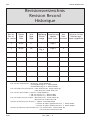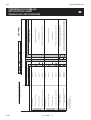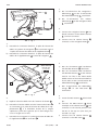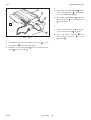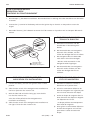
1
Yaris
TNS310 (Traffic) Plus
LHD Einbauanleitung
LHD installation instructions
LHD instructions d’installation
Model year: 2005
Vehicle code: **P90L-****KW
Part number TNS310 Plus: • Bracket: PZ425-B0330-60
• Sub wire harness No 1: 08673-64801
• Sub wire harness No 2: 08673-64800
Part number TNS310 Traffic Plus: • RDS-antenna kit: PZ445-T9281-00
• RDS-tuner kit: PZ445-T9331-00
Manual ref. no: AIM 000 488-2
Yaris
TNS310 TRAFFIC PLUS
Revisionsverzeichnis
Revision Record
Historique
Rev. Nr.
Rev. No
No. version
Datum
Date
Date
Seite
Page
Page
Abbildung Aktualisierung
Neu
Gelöschte Schritte
Picture
Update
New
Deleted steps
Image
Mise à jour Nouveau Etapes supprimées
2
07-07
17
–
Step 2
2
07-07
18
Abb. 4
Fig. 4
Step 4
X
TNS 310 Plus Teilenummer: • Halterung: PZ425-B0330-60
• Zusatzkabelstrang Nr. 1: 08673-64801
• Zusatzkabelstrang Nr. 2: 08673-64800
TNS 310 Traffic Plus Teilenummer: • RDS-Antennensatz: PZ445-T9281-00
• RDS-Tunersatz: PZ445-T9331-00
TNS 310 Plus part number: • Bracket: PZ425-B0330-60
• Sub wire harness No 1: 08673-64801
• Sub wire harness No 2: 08673-64800
TNS 310 Traffic Plus part number: • RDS-antenna kit: PZ445-T9281-00
• RDS-tuner kit: PZ445-T9331-00
Numéro de référence TNS 310 Plus: • Support: PZ425-B0330-60
• Faisceau de câbles supplémentaires No 1: 08673-64801
• Faisceau de câbles supplémentaires No 2: 08673-64800
Numéro de référence TNS310 Traffic Plus: • Kit antenne RDS : PZ445-T9281-00
• Kit tuner RDS: PZ445-T9331-00
07-07
Yaris (LHD) - 2
Yaris
TNS310 TRAFFIC PLUS
VORSICHTSMASSREGELN
PRECAUTIONS
PRECAUTIONS
LESEN SIE BITTE DIESE VORSICHTSMAßREGELN FÜR DEN EINBAU SORGFÄLTIG DURCH
PLEASE READ THOROUGHLY THESE PRECAUTIONS BEFORE THE INSTALLATION
PRECAUTIONS A LIRE ATTENTIVEMENT AVANT L’INSTALLATION
• Darauf achten, das negative (-) Kabel von
Batterieanschlüssen abzunehmen.
• Be sure to disconnect the negative (-) lead
from the battery terminals.
• N’oubliez pas de débrancher le fil négatif
(-) des bornes de la batterie.
• Die hintere Verkabelung oder den
Kabelstrang des angezogenen Teils
nicht verdrehen.
• Do not pinch the rear wiring or harness in the tightened part.
• Ne pincez pas la partie serrée du faisceau ou du câblage arrière.
• Beim Verlegen der Kabel durch das Instrumentenbrett oder
andere Verkleidungen eine Durchführungsdichtung verwenden, damit das System wasIst wasserdicht - OK!!
serdicht bleibt.
waterproof - O.K. !!
Etanchéité à l’eau - OK!!
• Beim Führen eines Kabels durch
Durchführungstülle
eine Öffnung das Kabel mit
Grommet
Passe-fil
Klebeband schützen.
• When passing the wires through
Umwickeln
the dashboard or other panels, use Taping
Taraudage
a grommet to ensure waterproofing.
• Protect the wiring with tape when it is passed through a
hole.
• Lorsque vous glissez les fils à travers le tableau de bord ou
d’autres panneaux, protégez-les contre l’humidité à l’aide
d’un passe-fil en caoutchouc.
• Protégez le cablâge avec de la mousse là où il traverse un
orifice.
• Beim Abnehmen der Anschlüsse die Stecker anfassen. Nie
an der Verkabelung ziehen.
Nein!
Stop it !
• When disconnecting the connectors,
Arrêtez!
be sure to grip the connector body.
Do not tug on the wiring.
• Saisissez le connecteur proprement
dit lorsque vous le débranchez. Ne
tirez pas sur le câblage.
• Niemals mit Kraft an Verkabelung im Fahrzeug ziehen. Ein
festes Ziehen kann dazu führen, dass Steckverbinder auseinandergezogen werden oder dass ein Kabel oder ein
Kabelstrang reißt.
• Do not forcibly pull any car wiring
harness. Rough tugging may result
in opened connections, or a broken
wire or harness.
• Ne tirez pas exagérément sur les
faisceaux de câbles. Vous pourriez
débrancher des connexions, voire même briser le faisceau
ou un de ses fils.
07-07
• Überprüfen, dass Beleuchtungsanlage, Sirene/ Signalhorn, Scheibenwischer und andere Ausrüstungen
normal funktionieren.
• Confirm that lamps, horn, wiper and
other car accessories operate normally.
• Vérifiez le bon fonctionnement des feux, de l’avertisseur,
desessuie-glaces et des autres accessoires du véhicule.
• Das Fahrzeug mit Kotflügelabdeckungen, Sitzschonbezügen usw. schützen.
• Protect your car with fender covers,
seat and so on.
• Protégez votre véhicule par des housses de siège, des housses d’aile, etc.
• Beim Anziehen von Schrauben oder
Muttern die vorgeschriebenen Werkzeuge verwenden.
• Use the correct tool when tightening
bolts or nuts.
• Serrez les boulons et les écrous avec
l’outil adéquat.
• Vor dem Bohren eines Lochs überprüfen,
dass die Rückwand frei ist.
• Before drilling a hole, check that the
rear of the mounting wall is clear.
• Avant de percer un trou, vérifiez s’il y a
un espace libre suffisant à l’arriére de la
paroi de fixation.
• Sorgfältig auf das richtige Anziehen
von Steckverbindern und Anschlüssen achten.
• Be sure to firmly tighten connectors
and terminals.
• N’oubliez pas de serrer correctement les connecteurs et des
bornes.
Vollständig einstecken
Insert completely
Insérez à fond
• Vor dem Anschluss der Kabel an die
Batterie die Kabelverbindungen,
Kabelstrang usw. prüfen und
darauf achten, dass sie richtig
gesichert sind.
• Before connecting the power
wiring to the battery, check the wiring connections, harness,
etc. to see that they are properly secured.
• Avant de raccorder le fil d’alimentation à la batterie, vérifiez
si les connexions des câblages, le faisceau de câbles, etc.
sont correctement fixés.
• Karosserie und Verkleidungen in der Nähe des Einbauortes
prüfen, damit kein Schmutz oder Kratzer von den Einbauarbeiten zurückbleiben.
• Check body and trim near area of installation to be certain
no dirt or scratches resulted from the installation.
• Vérifiez l’emplacement de l’installation ainsi que la surface
avoisinante en vérifiant qu’il ne reste ni salissures ni éraflures.
Yaris (LHD) - 3
Yaris
TNS310 TRAFFIC PLUS
INHALTSVERZEICHNIS
TABLE OF CONTENTS
TABLE DES MATIERES
Revisionsverzeichnis
Revision Record
Historique ........................................................................................................................................................
2
Vorsichtsmaßregeln
Precautions
Précautions ......................................................................................................................................................
3
Verwendungstabelle
Application Chart
Tableau des applications ..................................................................................................................................
5
TNS310 Navigationssystembaugruppe
TNS310 Navigation System Assembly
Montage du système de navigation TNS 310 ..................................................................................................
6
Systemaufbau
System Layout
Disposition du sytème .....................................................................................................................................
8
Anschlussverfahren
How to Connect
Procedure de raccordement ............................................................................................................................
9
Ausbau aus dem Fahrzeug
Vehicle Disassembly
Demontage du véhicule .................................................................................................................................. 10
Einbau der GPS-Antenne
GPS Antenna Installation
Installation de l’antenne GPS ........................................................................................................................... 16
Einbau des Hauptkabelstrangs
Wire Harness Installation
Installation du faisceau de câbles ..................................................................................................................... 19
Einbau des Computers
Computer Installation
Installation de l’ordinateur................................................................................................................................ 26
TNS310 Traffic Plus Systemaufbau
TNS310 Traffic Plus System Layout
Disposition du Systeme TNS310 Traffic Plus .................................................................................................... 28
Systemstart
System Start Up
Démarrage du système .................................................................................................................................... 40
HINWEIS
Lesen Sie vor dem Einbau von TNS310 unbedingt die allgemeinen Einbauanweisungen (gemeinsamer
Teil).
REMARK:
Be sure to read the General Installation Instructions (Common Section) before installing TNS 310.
REMARQUE:
Veuillez lire les Instructions générales d’installation (Section Commune) avant d’installer le TNS 310.
07-07
Yaris (LHD) - 4
UDA LOW GRADE
UDA HIGH GRADE
07-07
Yaris (LHD) - 5
NAVIGATION
86120-52480
86120-52480
86120-52480
86120-52480
CD-Tuner high grade + TNS310 PLUS
or TNS310 TRAFFIC PLUS
CD-Tuner high grade + H/A CD-Changer + TNS310 PLUS
or TNS310 TRAFFIC PLUS
9
10
(2)
* Subwoofer not compatible with Navigation
Located under the LH seat.
Located under the RH-seat.
86120-52480
CD-Tuner high grade + H/A CD changer + Subwoofer
8
(1)
86120-52480
CD-Tuner high grade + Subwoofer
7
86120-52480
CD-Tuner high grade (only)
5
86120-52480
86120-52470
CD-Tuner low grade + H/A CD changer + Subwoofer
4
CD-Tuner high grade + H/A CD changer
86120-52470
CD-Tuner low grade + Subwoofer
3
6
86120-52470
86120-52470
HEAD UNIT
CD-Tuner low grade + H/A CD changer
CD-Tuner low grade (only)
(1)
(1)
(1)
(1)
(1)
(1)
(1)
(1)
(2)
(2)
(2)
(2)
+ ADD-ON UNIT(S)
(LHD+RHD)
(2)
(2)
(2)
(2)
"W/H 08695-00370 + W/H 08673-64801+ Bracket PZ425-B0330-60 + Bracket PZ425-B0220-60"
"W/H 08695-00370 + W/H 08673-64801+ Bracket PZ425-B0330-60 + Bracket PZ425-B0220-60"
"W/H 08673-64800 + W/H 08673-64801+ Bracket PZ425-B0330-60"
"W/H 08673-64800 + W/H 08673-64801+ Bracket PZ425-B0330-60"
"W/H 08695-00370 + Bracket PZ425-B0220-60 + PZ425-B0221-60"
"Bracket PZ425-B0221-60"
"W/H 08695-00370 + Bracket PZ425-B0220-60"
"-"
"W/H 08695-00370 + Bracket PZ425-B0220-60 + PZ425-B0221-60"
"Bracket PZ425-B0221-60"
"W/H 08695-00370 + Bracket PZ425-B0220-60"
"-"
REQUIRED ADDITIONAL PARTS
Navigation System TNS310 PLUS (08545-52802)
Navigation System TNS310 TRAFFIC PLUS (PZ445-00330-00)
YARIS **P90**-*****W
Subwoofer (08691-00834) *
Hide-Away CD-Changer TM0461 (08601-00911)
2
1
COMBINATION
TMME-CSGDP - October 17th, 2005
AUDIO & NAVIGATION APPLICATION CHART
Yaris
TNS310 TRAFFIC PLUS
VERWENDUNGSTABELLE
APPLICATION CHART
TABLEAU DE APPLICATIONS
Yaris
TNS310 TRAFFIC PLUS
TNS310 PLUS SYSTEMBAUGRUPPE
TNS310 PLUS SYSTEM ASSEMBLY
MONTAGE DU SYSTEME TNS310 PLUS
1
4
08545-52801
2
*1
8
3
5
6
9
10
7
11
Nr. / NO
Bezeichnung / Description / Référence
Menge / Qty
1
COMPUTER / COMPUTER / ORDINATEUR
1
2
KABELSTRANG / WIRE HARNESS / FAISCEAU DE CABLES
1
3
GPS-ANTENNE / GPS ANTENNA / ANTENNE GPS
1
4
NAVIGATIONS-DISC (*1) / NAVIGATION DISC (*1) /
DISQUE DE NAVIAGATION (*1)
1
5
COMPUTER-HALTERUNG / COMPUTER BRACKET / SUPPORT DE L’ORDINATEUR
2
6
BOLZEN (M5 x 8) / BOLT (M5 x 8) / BOULON (M5 x 8)
4
7
KABELKLEMME / WIRE CLAMP / AGRAFE POUR CORDON
2
8
SCHAUMSTOFFKLEBEBAND / FOAM TAPE / MOUSSE ADHESIF
2
9
KABELBINDER / WIRE TIE / LIEN POUR CABLE
5
10
MASSEPLATTE / EARTH PLATE / PLAQUE DE MISE AL A MASSE
1
11
KLEBEBAND / ADHESIVE TAPE / BANDE ADHESIVE
4
*1: NAVIGATIONS DISC (DVD-ROM) 4 ist nicht im Navigationssatz enthalten.
*1: NAVIGATION DISC (DVD-ROM) 4 is not included in the navigation kit.
*1: DISQUE DE NAVIGATION (DVD-ROM) 4 non fourni avec le kit de navigation.
07-07
Yaris (LHD) - 6
Yaris
TNS310 TRAFFIC PLUS
FÜR HALTERUNGSSATZ
FOR BRACKET SET
POUR JEU DE SUPPORTS
Nr
NO
NO
PZ425-B0330-60
Bezichnung
Description
Référence
Menge
Quantity
Quantité
1
HALTERUNG
BRACKET
SUPPORT
1
2
BOLZEN (M6)
BOLT (M6)
BOULON (M6)
2
1
2
FÜR ZUSATZKABELSTRANG
FOR SUB WIRE HARNESS
POUR FAISCEAU DE CABLES SUPPLEMENTAIRES
Nr
NO
NO
5
Bezichnung
Description
Référence
08673-64801
Menge
Quantity
Quantité
ZUSATZKABELSTRANG NR.1
SUB WIRE HARNESS NO.1
FAISCEAU DE CABLES SUPPLEMENTAIRES NO.1
5
1
FÜR ZUSATZKABELSTRANG
FOR SUB WIRE HARNESS
POUR FAISCEAU DE CABLES SUPPLEMENTAIRES
Nr
NO
NO
6
07-07
Bezichnung
Description
Référence
08673-64800
Menge
Quantity
Quantité
ZUSATZKABELSTRANG NR.2
SUB WIRE HARNESS NO.2
FAISCEAU DE CABLES SUPPLEMENTAIRES NO.2
Yaris (LHD) - 7
1
6
Yaris
TNS310 TRAFFIC PLUS
TNS310 PLUS SYSTEMAUFBAU
TNS310 PLUS SYSTEM LAYOUT
DISPOSITION DU SYSTEME TNS310 PLUS
3
Verbindungsstecker (Geschwindigkeitssensorkabel)
Splicing connector (Speed sensor wire)
Connecteur de raccordement
(Fil du détecteur de vitesse)
Für Yaris TS
For Yaris TS
Pour Yaris TS
Verbindungsstecker (TX+ sensorkabel
Splicing connector (TX+ sensor wire)
Connecteur de raccordement
(Fil du détecteur TX+)
Verbindungsstecker (TX- sensorkabel
Splicing connector (TX- sensor wire)
Connecteur de raccordement
(Fil du détecteur TX-)
Verbindungsstecker (Rückfahrsensorkabel)
Splicing connector (Reverse sensor wire)
Connecteur de raccordement
(Fil du détecteur de marche arrière)
3
Antennenkabel
Antenna wire
Cordon de l’antenne
Überschüssiges Kabel
Excess wire
Fil inutilisé
2
Nr. / NO
07-07
1
Bezeichnung / Description / Référence
Menge / Qty
1
COMPUTER / COMPUTER / ORDINATEUR
1
2
KABELSTRANG / WIRE HARNESS / FAISCEAU DE CABLES
1
3
GPS-ANTENNE / GPS ANTENNA / ANTENNE GPS
1
Yaris (LHD) - 8
Yaris
TNS310 TRAFFIC PLUS
ANSCHLUSSVERFAHREN
HOW TO CONNECT
PROCEDURE DE RACCORDEMENT
ANSCHLUSSMETHODE: CD TUNER MIT MULTI DISPLAY
CONNECTION METHOD: CD TUNER WITH MULTI DISPLAY
METHODE DE RACCORDEMENT: TUNER AVEC CD ET AFFICHAGE MULTIFONCTION
Verbindungsstecker (Rückfahrsensorkabel)
Splicing connector (Reverse sensor wire)
Connecteur de raccordement
(Fil du détecteur de marche arrière)
CD-Tuner mit Multi-Display
CD tuner with multi display
Tuner avec CD et affichage multifonction
5
6
3
10P
1
6P
8P
12P
20P
1P
Fahrzeugkabelstrang
Vehicle wire harness
Faisceau de câbles du véhicule
Verbindungsstecker (TX+ sensorkabel)
Splicing connector (TX+ sensor wire)
Connecteur de raccordement
(Fil du détecteur TX+)
Verbindungsstecker (TX- sensorkabel)
Splicing connector (TX- sensor wire)
Connecteur de raccordement (Fil du détecteur TX-)
8P
13P
2
Verbindungsstecker (Geschwindigkeitssensorkabel)
Splicing connector (Speed sensor wire)
Connecteur de raccordement
(Fil du détecteur de vitesse)
Antennenkabel
Antenna wire
Cordon de l’antenne
Informationen über den Ausbau von Fahrzeugteilen, einbaumethoden, Anzugsmomente, usw., siehe
Reparaturhandbuch.
Refer to the repair manual for information on removal of vehicle parts, installation methods, tightening
torque and so forth.
Reportez-vous au manuel de réparation pour plus d’informations sur la dépose des pièces du véhicule, les
méthodes d’installation, les couples de serrage, etc.
Nr. / NO
Bezeichnung / Description / Référence
Menge / Qty
1
COMPUTER / COMPUTER / ORDINATEUR
1
2
KABELSTRANG / WIRE HARNESS / FAISCEAU DE CABLES
1
3
GPS-ANTENNE / GPS ANTENNA / ANTENNE GPS
1
5
ZUSATZKABELSTRANG NR.1 / SUB WIRE HARNESS NO.1 /
FAISCEAU DE CABLES SUPPLEMENTAIRES NO.1
1
6
ZUSATZKABELSTRANG NR.2 / SUB WIRE HARNESS NO.2 /
FAISCEAU DE CABLES SUPPLEMENTAIRES NO.2
1
07-07
Yaris (LHD) - 9
Yaris
TNS310 TRAFFIC PLUS
TNS310 PLUS EINBAUANLEITUNG
TNS310 PLUS INSTALLATION INSTRUCTIONS
INSTRUCTIONS D'INSTALLATION DU TNS310 PLUS
• AUSBAU AUS DEM FAHRZEUG
• VEHICLE DISASSEMBLY
• DEMONTAGE DU VEHICULE
1.
An den schraffierten Bereichen Schutzklebeband anbringen.
ACHTUNG
Darauf achten, die Teile vorsichtig zu
entfernen, um die Verkleidung nicht zu
beschädigen.
1.
Put protective tape on the shaded areas.
CAUTION
Be sure to remove the parts carefully
so you do not damage the panels.
Abb. 1 - Fig. 1
1.
Recouvrez les zones ombrées avec de la bande adhésive de
protection.
ATTENTION
Retirez délicatement les pièces afin de ne pas endommager
les panneaux.
2.
7
Die Mittelkonsolenabdeckung entfernen
(L) 7 und (R) 7 .
: Clip (6x)
: Haken (8x)
2.
Remove the center cluster panel (L)
and (R) 7 .
7
: Clip (6x)
: Hook (8x)
2.
Déposez le panneau de la console centrale (L) 7 et (R) 7 .
: Clip (6x)
: Crochet (8x)
Abb. 2 - Fig. 2
07-07
Yaris (LHD) - 10
Yaris
TNS310 TRAFFIC PLUS
3.
8
An
den
schraffierten
Bereichen
Schutzklebeband
anbringen.
Die
Abdeckung der Instrumentenbaugruppe
8 entfernen.
: Clip (5x)
: Haken (4x)
ACHTUNG
Darauf achten, die Teile vorsichtig zu
entfernen, um die Verkleidung nicht zu
beschädigen.
3.
: Clip (5x)
Abb. 3 - Fig. 3
3.
Put protective tape on the shaded areas.
Remove the meter cluster panel 8 .
Recouvrez les zones ombrées avec de la bande adhésive de
protection. Déposez le panneau de la console du tableau de
bord 8 .
: Clip (5x)
: Hook (4x)
CAUTION
Be sure to remove the parts carefully
so you do not damage the panels.
: Crochet (4x)
ATTENTION
Retirez délicatement les pièces afin de ne pas endommager
les panneaux.
4.
100
Den CD-Tuner mit Multi-Display
fernen.
9
ent-
: Clip (4x)
100
9
4.
Remove the CD tuner with multi display
9 .
: Clip (4x)
100
4.
: Scrauben (4x)
: Screw (4x)
Déposez le tuner avec CD et affichage
multifonction 9 .
: Clip (4x)
100
Abb. 4 - Fig. 4
07-07
Yaris (LHD) - 11
: Vis (4x)
Yaris
TNS310 TRAFFIC PLUS
5.
10
101
Das Kombinationsinstrument
101
5.
entfernen.
: Scrauben (2x)
Remove the combination meter
101
5.
10
10 .
: Screw (2x)
Déposez les instruments combinés
101
10 .
: Vis (2x)
Abb. 5 - Fig. 5
6.
102
Die untere Verkleidung der Instrumententafel (L) 11 ausbauen.
102
: Scrauben (2x)
: Haken (1x)
6.
Remove the instrument panel under
cover (L) 11 .
102
: Screw (2x)
: Hook (1x)
6.
11
Déposez la garniture inférieure du
tableau de bord (gauche) 11 .
102
: Vis (2x)
: Crochet (1x)
Abb. 6 - Fig. 6
7.
12
Das Instrumententafelfach
12
ausbauen.
: Haken (2x)
7.
Remove the instrument panel box
12 .
: Hook (2x)
7.
Déposez la boîte du tableau de bord
12 .
: Crochet (2x)
Abb. 7 - Fig. 7
07-07
Yaris (LHD) - 12
Yaris
TNS310 TRAFFIC PLUS
8.
13
Das Handschuhfach entfernen
13 .
: Haken (5x)
8.
Remove the glove box
13 .
: Hook (5x)
8.
Déposez la boîte à gants
13 .
: Crochet (5x)
Abb. 8 - Fig. 8
9.
Die untere Verkleidung der Instrumententafel (R) 14 ausbauen.
: Haken (3x)
9.
Remove the instrument panel under
cover (R) 14 .
: Hook (3x)
9.
Remove the instrument panel under
cover (droite) 14 .
: Crochet (3x)
14
Abb. 9 - Fig. 9
10. Die vordere Einstiegsverkleidung (R)
entfernen .
15
15
: Clip (2x)
: Haken (2x)
10. Remove the front door scuff plate (R)
15 .
: Clip (2x)
: Hook (2x)
10. Déposez la plaque de protection
pas de porte avant (droite).
: Clip (2x)
: Crochet (2x)
Abb. 10 - Fig. 10
07-07
Yaris (LHD) - 13
15
du
Yaris
TNS310 TRAFFIC PLUS
16
11. Die Windlaufseitenverkleidung (R)
ausbauen.
16
: Clip (1x)
: Haken (1x)
11. Remove the cowl side panel (R)
16 .
: Clip (1x)
: Hook (1x)
11. Enlevez le panneau du carter de roue
(droite) 16 .
: Clip (1x)
: Crochet (1x)
Abb. 11 - Fig. 11
12. Die hintere Einstiegsverkleidung (R)
entfernen.
17
: Haken (6x)
12. Remove the rear door scuff plate (R)
17 .
: Hook (6x)
12. Déposez la plaque de protection du pas
de porte arrière (droite) 17 .
: Crochet (6x)
17
Abb. 12 - Fig. 12
13. Die B-Säulenverkleidung (R)
nen.
18
18
entfer-
: Clip (2x)
: Haken (2x)
13. Remove the center pillar lower garnish
(R) 18 .
: Clip (2x)
: Hook (2x)
13. Déposez la garniture inférieure du pillier
central (droite) 18 .
: Clip (2x)
: Crochet (2x)
Abb. 13 - Fig. 13
07-07
Yaris (LHD) - 14
Yaris
TNS310 TRAFFIC PLUS
14. Den Beifahrersitz
19
103
19
entfernen.
: Bolzen (4x)
14. Remove the passenger’s seat
103
: Bolt (4x)
14. Déposez le siège du passager
103
103
Abb. 14 - Fig. 14
07-07
Yaris (LHD) - 15
19 .
: Boulon (4x)
19 .
Yaris
TNS310 TRAFFIC PLUS
• EINBAU DER GPS-ANTENNE
• GPS ANTENNA INSTALLATION
• INSTALLATION DE L’ANTENNE GPS
SCHAUMSTOFFKLEBEBAND
1.
a)
8
‘Großes Stück’
• Für überschüssigen Kabelstrang und
Antennenkabel
‘Mittelgroßes Stück’
• Zum Verlegen von Kabelstrang und
Antennenkabel
• Für überschüssiges Geschwindigkeitssensorkabels
• Für überschüssiges Rückfahrsensorkabel
• Zum Abdecken der Kanten, um den
Kabelstrang vor Beschädigungen zu
schützen.
‘Kleines Stück’
• Zum Verlegen des Rückfahrsensorkabels
• Zum Verlegen des Geschwindigkeitssensorkabels
• Zum Verlegen des Antennenkabels
x2
x 10
x8
Abb. 1 - Fig. 1
PROCEDURES DE DECOUPE
DE LA MOUSSE
FOAM TAPE CUT PROCEDURES
1.
a)
Cut the foam tape 8 into 2 large pieces and 10 middle
pieces 8 small pieces as shown in the illustration.
‘Large piece’
• For excess length of wire harness & antenna wire
‘Middle piece’
• For wire harness & antenna wire routing
• For excess length of speed sensor wire
• For excess length of reverse sensor wire
• For covering the edges to prevent the wire harness damage
‘Small piece’
• For reverse sensor wire routing
• For speed sensor wire routing
• For antenna wire routing
07-07
Das Schaumstoffklebeband 8 in 2
große, 10 mittelgroße und 8 kleine
Stücke schneiden, wie inder Abblidung
gezeigt.
Yaris (LHD) - 16
1.
a)
Découpez la bande de mousse 8 en 2
grands morceaux, 10 morceaux de taille
moyenne et 8 petits morceaux, de la
manière illustrée.
‘Grand morceau
• Pour la longueur inutilisée du faisceau de
câbles et du cordon de l’antenne
‘Morceau moyen’
• Pour l’acheminement du faisceau de
câbles et du cordon de l’antenne
• Pour la longueur inutilise du fil du
détecteur de vitesse
• Pour la longueur inutilise du fil du
détecteur de marche arrière
• Pour recouvrir les bords afin d'éviter
d'endommager le faisceau de câbles
‘Petit morceau’
• Pour l’acheminement du fil du détecteur
de marche arrière
• Pour l’acheminement du fil du détecteur
de vitesse
• Pour l’acheminement du cordon de l’antenne
Yaris
TNS310 TRAFFIC PLUS
Für Yaris NON TS.
8
10
2.
a)
Das Antennenkabel 3 mittels Schaumstoffklebeband 8 befestigen.
b)
Die Masseplatte 10 und die Antenne an
der Rückseite des Kombinationsinstruments 10 anbringen.
For Yaris NON TS.
3
2.
3
a)
Fix the antenna wire
tape 8 .
b)
Place the earth plate 10 and the
antenna on the back of the combination
meter 10 .
10
Abb. 2 - Fig. 2
using the foam
Pour Yaris NON TS.
2.
10
101
Fixez le cordon de l’antenne
de mousse 8 .
b)
Placez la plaque de mise à la masse 10
et l'antenne à l'arrière des instruments
combinés 10 .
3.
Das Kombinationsinstrument
einbauen.
101
3.
3.
Yaris (LHD) - 17
wieder
10 .
: Screw (2x)
Replacez les instruments combinés
101
07-07
10
à l’aide
: Scrauben (2x)
Refit the combination meter
101
Abb. 3 - Fig. 3
3
a)
: Vis (2x)
10 .
Yaris
TNS310 TRAFFIC PLUS
10
8
4.
Für Yaris TS.
a)
Das Antennenkabel 3 mittels Schaumstoffklebeband 8 befestigen.
b)
Die Masseplatte 10 und die Antenne an
der Vorderseite des Kombinationsinstruments anbringen.
4.
For Yaris TS.
a)
Fix the antenna wire
tape 8 .
b)
Place the earth plate 10 and the
antenna in front of the combination
meter.
4.
Pour Yaris TS.
a)
Fixez le cordon de l’antenne
de mousse 8 .
b)
Placez la plaque de mise à la masse 10
et l'antenne en face des instruments
combinés.
3
Abb. 4 - Fig. 4
07-07
Yaris (LHD) - 18
3
using the foam
3
à l’aide
Yaris
TNS310 TRAFFIC PLUS
• INSTALLATION DES KABELSTRANGS
• WIRE HARNESS INSTALLATION
• INSTALLATION DU FAISCEAU DE CABLES
Verbindungsstecker
Splicing connector
Connecteur de raccordement
ANSCHLUSSVERFAHREN FÜR
VERBINDUNGSSTECKER
Zange
Pliers
Pince
1.
Fahrzeugkabelstrang
Vehicle wire harness
Faisceau de câbles du véhicule
a)
Den Vinylschlauch oder die Isolierbandumwicklung vom Fahrzeugkabelstrangstück entfernen, das angeschlossen werden soll.
b)
Den anzuschließenden Fahrzeugkabelstrang sicher in den Führungsschlitz einführen.
c)
Nach dem Einführen des Fahrzeugkabelstrangs in den Führungsschlitz, den
Verbindungsstecker mit einer Zange
oder einem anderen Werkzeug fest verschließen, bis der Stecker einrastet.
Abb. 1 - Fig. 1
CONNECTING PROCEDURES
OF SPLICING CONNECTOR
PROCEDURES DE CONNEXION
DU CONNECTEUR DE
RACCORDEMENT
1.
a)
Remove the vinyl tube or wrapping tape from the length of
vehicle wire harness to be connected.
b)
Insert the vehicle wire harness to be connected securely into
the guide slit.
c)
After inserting the vehicle wire harness into the guide slit,
lock the splicing connector securely using a pair of pliers or
the equivalent until the connector clicks.
07-07
Yaris (LHD) - 19
1.
a)
Retirez la gaine ou la bande de la
longueur du faisceau de câbles du
véhicule à raccorder.
b)
Insérez convenablement dans la fente
du guide le faisceau de câbles du
véhicule que vous souhaitez raccorder.
c)
Après avoir inséré le faisceau de câbles
du véhicule dans la fente du guide, verrouillez convenablement le connecteur
de raccordement avec une pince ou un
outil similaire, jusqu'à ce que vous
entendiez un déclic.
Yaris
TNS310 TRAFFIC PLUS
5
8-Stift (weiß)
8P(white)
8 pôles (blanc)
VORBEREITUNG VOR
DEM VERKABELN
8-Stift (Stecker)
8P(male)
8 pôles (mâle)
2.
a)
Klebeband
Tape
Bande adhésive
2
Stift-Stecker
verbinden.
8-Stift (weiß)
8P(white)
8 pôles (blanc)
13-Stift (weiß)
13P(white)
13 pôles (blanc)
Kabelstrangs
2
.
Das TX+ Sensorkabel (gelb) 2 mit
Terminal 9 des 12-Stift-Steckers (weiß)
auf der Seite des Zusatzkabelstrangs Nr.
2 6 verbinden.
c)
Das TX- Sensorkabel (gelb/schwarz) 2
mit Terminal 10 des 12-Stift-Steckers
(weiß)
auf
der
Seite
des
6
Zusatzkabelstrangs Nr. 2
verbinden.
12-Stift auf der Kabelstrangseite
12P on the wire harness side
12 pôles du faisceau de câbles
ACHTUNG
Den 8-Stift-Stecker von Kabelstrang
2 mit Klebeband befestigen.
10 9
Lasche
Tab
Onglet
des
(weiß)
des
mit dem 8-
5
b)
6
12-Stift (weiß)
12P(white)
12 pôles (blanc)
Den
8-Stift-Stecker
Zusatzkabelstrang Nr. 1
Verbindungsstecker
Splicing connector
Connecteur de
raccordement
6
PREPARATION DU CABLAGE
2
TX- sensorkabel (Gelb/Schwarz)
TX- sensor wire (yellow/black)
Fil du détecteur TX- (jaune/noir)
2
TX+ sensorkabel (Gelb)
TX+ sensor wire (yellow)
Fil du détecteur TX+ (jaune)
2.
a)
Raccordez le connecteur à 8 pôles
(blanc) du sous-faisceau de câbles No. 1
5 au connecteur à 8 pôles du faisceau
de câbles 2 .
b)
Raccordez le fil du détecteur TX+ (jaune)
2 à la borne 9 du connecteur à 12
pôles (blanc) du sous-faisceau de câbles
No. 2 6 .
c)
Raccordez le fil du détecteur TX(jaune/noir) 2 à la borne 10 du connecteur à 12 pôles (blanc) du sous-faisceau de câbles No. 2 6 .
Abb. 2 - Fig. 2
PREPARATION BEFORE WIRING
2.
a)
Connect 8P connector (white) of the sub wire harness No.1
5 to 8P connector of wire harness 2 .
b)
Connect the TX+ sensor wire (yellow) 2 to terminal 9 of
12P connector (white) on the sub wire harness No.2 6
side.
c)
2
Connect the TX- sensor wire (yellow/black)
to terminal
10 of 12P connector (white) on the sub wire harness No.2
6 side.
CAUTION
Fix 8P (Male) of wire harness
07-07
2
with tape.
Yaris (LHD) - 20
ATTENTION
Fixez le connecteur à 8 pôles (Mâle) du
faisceau de câbles 2 à l’aide de bande
adhésive.
Yaris
TNS310 TRAFFIC PLUS
3.
24-Stift (weiß)
24P(white)
24 pôles (blanc)
a)
Kabelstrang 2 und Antennenkabel 3
verlegen, wie in der Abbildung gezeigt.
b)
Den 24-Stift-Stecker (weiß) lösen.
3.
3
a)
Route the wire harness 2 and antenna
wire 3 as shown in the illustration.
b)
Disconnect the 24P connector (White).
3.
2
a)
Acheminez le faisceau de câbles 2 et le
cordon de l’antenne 3 , de la manière
illustrée.
b)
Débranchez le connecteur à 24 pôles
connector (blanc).
Abb. 3 - Fig. 3
24-Stift (weiß)
24P(white)
24 pôles (blanc)
Lasche
Tab
Onglet
24-Stift auf der Kabelstrangseite
24P on the wire harness side
24 pôles du faisceau de câbles
4.
a)
Das Geschwindigkeitssensorkabel (violett/weiß) 2 an Terminal 16 des 24Stift-Steckers (weiß) anschließen.
b)
Den 24-Stift-Stecker (weiß) wieder anschließen.
16
4.
Verbindungsstecker
Splicing connector
Connecteur de raccordement
2
Geschwindigkeitssensorkabel (violett/weiß)
Speed sensor wire (violet/white)
Fil du détecteur de vitesse(violet/blanc)
a)
Connect the speed sensor wire (violet/
white) 2 to terminal 16 of the 24P connector (white).
b)
Reconnect the 24P connector (white).
4.
a)
Raccordez le fil du détecteur de vitesse
(violet/blanc) 2 à la borne 16 du connecteur à 24 pôles (blanc).
b)
Rebranchez le connecteur à 24 pôles
(blanc).
5.
Geschwindigkeitssensorkabel 2 , wie in
der Abbildung gezeigt, mit Schaumstoffklebeband 8 befestigen.
5.
Secure the speed sensor wire 2 as
shown in the illustration using the foam
tape 8 .
5.
Fixez le fil du détecteur de vitesse 2 de
la manière illustrée, à l’aide de mousse
8 .
Abb. 4 - Fig. 4
2
Geschwindigkeitssensorkabel
Speed sensor wire
Fil du détecteur de vitesse
8
Abb. 5 - Fig. 5
07-07
Yaris (LHD) - 21
Yaris
TNS310 TRAFFIC PLUS
6.
30-Stift (weiß)
30P(white)
30 pôles (blanc)
a)
Das Rückfahrsensorkabel 2 , wie in der
Abbildung gezeigt, verlegen.
b)
Den 30-Stift-Stecker (weiß) lösen
6.
2
a)
Route the reverse sensor wire
shown in the illustration.
as
b)
Disconnect the 30P connector (white).
6.
2
Rückfahrsensorkabel
Reverse sensor wire
Fil du détecteur de marche arrière
a)
Acheminez le fil du détecteur de marche
arrière 2 de la manière illustrée.
b)
Débranchez le connecteur à 30 pôles
connector (blanc).
Abb. 6 - Fig. 6
30-Stift auf der Kabelstrangseite
30P on the wire harness side
30 pôles du faisceau de câbles
30-Stift (weiß)
30P(white)
30 pôles (blanc)
7.
a)
Das Rückfahrsensorkabel (rot/blau) 2
mit Anschluss 30 des 30-Stift-Steckers
(Weiß) verbinden.
b)
Den 30-Stift-Stecker (weiß) wieder anschließen.
7.
Verbindungsstecker
Splicing connector
Connecteur de raccordement
Lasche
Tab
Onglet
2
Rückfahrsensorkabel (rot/blau)
Reverse sensor wire (red/blue)
Fil du détecteur de marche arrière (rouge/bleu)
Abb. 7 - Fig. 7
07-07
Yaris (LHD) - 22
a)
Connect the reverse sensor wire
(red/blue) 2 to terminal 30 of the 30P
connector (white).
b)
Reconnect the 30P connector (white).
7.
a)
Raccordez le fil du détecteur de marche
arrière (rouge/bleu) 2 à la borne 30 du
connecteur à 30 pôles (blanc).
b)
Rebranchez le connecteur à 30 pôles
(blanc).
Yaris
TNS310 TRAFFIC PLUS
2
Rückfahrsensorkabel
Reverse sensor wire
Fil du détecteur de marche arrière
8.
Das Rückfahrsensorkabel 2 , wie in der
Abbildung gezeigt, mit Schaumstoffklebeband 8 sichern.
8
8
: Schaumstoffklebeband (5x)
ACHTUNG
Das Kabel etwas überhängen lassen,
damit die untere Verkleidung der
Instrumententafel bei Bedarf ausgebaut
und wieder eingebaut werden kann.
Untere Verkleidung der Instrumententafel (L)
Instrument panel under cover (L)
Garniture inférieure du tableau de bord (G)
Fixez le fil du détecteur de marche arrière
illustrée, à l'aide de mousse 8 .
8
2
de la manière
: Foam tape (5x)
WARNING
Leave some slack on the wiring for refitting and removal of the instrument
panel under cover when needed.
: Bande de mousse (5x)
ATTENTION
Ne tendez pas complètement le câblage pour permettre
la remise en place et le retrait éventuel de la garniture
inférieure du tableau de bord.
07-07
Secure the reverse sensor wire 2 as
shown in the illustration using the foam
tape 8 .
8
Abb. 8 - Fig. 8
8.
8.
Yaris (LHD) - 23
Yaris
TNS310 TRAFFIC PLUS
2
Geschwindigkeitssensorkabel
Speed sensor wire
Fil du détecteur de vitesse
8
9.
a)
Den
10-Stift-Stecker
(weiß)
am
2
Kabelstrang
an den 10-Stift-Stecker
(weiß)
auf
der
Fahrzeugseite
anschließen.
b)
Das überschüssige Geschwindigkeitssensorkabel mit Schaumstoffklebeband
8 befestigen, wie in der Abbildung
gezeigt.
9.
10-Stift (weiß)
10P(white)
10 pôles (blanc)
Abb. 9 - Fig. 9
a)
Connect 10P connector (white) on the
wire harness 2 side to 10P connector
(white) on the vehicle side.
b)
Secure the excess speed sensor wire as
shown in the illustration using the foam
tape 8 .
9.
a)
Raccordez le connecteur à 10 pôles (blanc) du faisceau de
câbles 2 au connecteur à 10 pôles (blanc) du côté du
véhicule
b)
Fixez la longueur excédentaire du fil du détecteur de vitesse
de la manière illustrée, à l’aide de mousse 8 .
9
Fahrzeugkabelstrang
Vehicle wire harness
Faisceau de câbles
du véhicule
2
10. Den
Kabelstrang
und
das
3
Antennenkabel
mit den Kabelbindern
9 am Fahrzeugkabelstrang befestigen.
9
: Kabelbinder (2x)
10. Secure the wire harness 2 and antenna
wire 3 to the vehicle wire harness using
the wire ties 9 .
3
9
: Wire ties (2x)
10. Fixez le faisceau de câbles 2 et le fil
d'antenne 3 au faisceau de câbles du
véhicule à l'aide de liens pour câble 9 .
9
2
Abb. 10 - Fig. 10
07-07
Yaris (LHD) - 24
: Lien pour cable (2x)
Yaris
TNS310 TRAFFIC PLUS
11. Den CD-Tuner mit Multi-Display wieder
einbauen 9 .
9
: Clip (4x)
100
: Haken (4x)
11. Refit the CD tuner with multi display
9 .
: Clip (4x)
100
: Bolt (4x)
11. Replacez le tuner avec CD et affichage
multifonction 9 .
: Clip (4x)
100
100
: Boulon (4x)
Abb. 11 - Fig. 11
12.
8
a)
Das Schaumstoffklebeband 8 an den
Kanten an der Fahrzeugseite befestigen,
wie in der Abbildung gezeigt.
b)
2
Den
Kabelstrang
und
das
3
Antennenkabel
in den Einbaubereich
des Computers verlegen und mit
Schaumstoffklebeband 8 befestigen.
c)
Den überschüssigen Kabelstrang 2 und
das Antennenkabel 3 mit Schaumstoffklebeband 8 befestigen, wie in der
Abbildung
2
8
8
: Schaumstoffklebeband (6x)
8
3
12.
Abb. 12 - Fig. 12
12.
8
a)
Fixez la mousse
manière illustrée.
b)
Acheminez le faisceau de câbles 2 et le fil d'antenne 3
jusqu'à la zone d'installation de l'ordinateur et fixez-les avec
de la mousse 8 .
c)
Fixez la longueur excédentaire du faisceau de câbles 2 et
du cordon de l’antenne 3 de la manière illustrée, avec de
la mousse 8 .
8
07-07
sur les bords du côté véhicule, de la
: Bande de mousse (6x)
Yaris (LHD) - 25
a)
Attach foam tape 8 to the edges on the
vehicle side as shown in the illustration.
b)
Route the wire harness 2 and antenna
wire 3 to the computer installation area
and fix them with foam tape 8 .
c)
Secure the excess length of the wire harness 2 and antenna wire 3 as shown
in the illustration using foam tape 8 .
8
: Foam tape (6x)
Yaris
TNS310 TRAFFIC PLUS
Den Teppichboden in Übereinstimmung
mit den links gezeigten Abmessungen
aufschneiden.
80
1.
Slit the floor carpet in accordance with
the measurements shown in the left.
1.
Incisez la moquette selon les mesures
indiquées à gauche ci-contre.
110
240 mm
1.
60 mm
30 mm
• EINBAU DES COMPUTERS
• COMPUTER INSTALLATION
• INSTALLATION DE L’ORDINATEUR
50 mm
155
30 mm
100
100
120
Abb. 1 - Fig. 1
13P
8P
2.
1P
1
a)
11
Das Klebeband
Halterung Nr. 1
gezeigt.
1
am Boden der
befestigen, wie
b)
Den 1-Stift-Stecker (GPS-Antenne 3 ),
den 8-Stift-Stecker und den 13-StiftStecker (Kabelstrang 2 ) an den
Computer 1 anschließen.
c)
Die Halterung Nr. 1 1 mit den Bolzen
6 am Computer 1 befestigen.
6
6
: Bolzen (4x)
Zum Einbau des Computers 1 wird eine
zusätzliche Halterung PZ425-B0330-60
benötigt.
1
2.
11 (80 x 35mm)
a)
Attach the adhesive tape 11 to the bottom of the bracket 1 as shown.
b)
Connect 1P connector (GPS antenna
3 ), 8P connector and 13P connector
(wire harness 2 ) to the computer 1 .
c)
Fit the bracket
using the bolts
6
1
6
to the computer
1
.
: Bolt (4x)
1
To install the computer 1 , an additional
bracket PZ425-B0330-60 is required.
Abb. 2 - Fig. 2
07-07
Yaris (LHD) - 26
Yaris
TNS310 TRAFFIC PLUS
2.
a)
Fixez la bande adhésive 11 sur le dessous du support No.1
1 , de la manière illustrée.
b)
Raccordez le connecteur à 1 pôle (antenne GPS 3 ), le connecteur à 8 pôles et le connecteur à 13 pôles (faisceau de
câbles 2 ) à l’ordinateur 1 .
c)
Fixez le support No.1
boulons 6 .
6
1
à l'ordinateur
1
à l'aide des
: Boulon (4x)
Installer l'ordinateur 1 , un support supplémentaire
PZ425-B0330-60 est requis.
3.
2
1
Den Computer 1 unter dem Fahrersitz
mit Bolzen 2 befestigen.
2
3.
Fix the computer 1 under the passenger’s seat using the bolts 2 .
2
3.
07-07
Yaris (LHD) - 27
: Bolt (2x)
Fixez l'ordinateur 1 sous le siège passager à l'aide des boulons 2 .
2
Abb. 3 - Fig. 3
: Bolzen (2x)
: Boulon (2x)
Yaris
TNS310 TRAFFIC PLUS
TNS310 TRAFFIC PLUS SYSTEMBAUGRUPPE
TNS310 TRAFFIC PLUS SYSTEM ASSEMBLY
MONTAGE DU SYSTEME TNS310 TRAFFIC PLUS
RDS-ANTENNENSATZ
RDS-ANTENNA KIT
KIT ANTENNE RDS
PZ445-T9281-00
I
II
III
IV
Nr.
NO.
NO.
I
II
III
IV
Bezeichnung
Part name
Référence
RDS-ANTENNENSTREIFEN
RDS-ANTENNA STRIP
JOINT D’ETANCHEITE DE L’ANTENNE-RDS
RDS-ANTENNENKABEL
RDS-ANTENNA WIRE
FIL DE L’ANTENNE RDS
GROUND BOLT
GROUND BOLT
GROUND BOLT
FAKRA CONNECTOR
FAKRA CONNECTOR
FAKRA CONNECTOR
RDS-TUNERSATZ
RDS-TUNER KIT
KIT TUNER RDS
07-07
Menge
Quantity
Quantité
PZ445-E9281-01
1
PZ445-E9281-00
1
-
1
PZ445-E9330-01
1
PZ445-T9331-00
B
A
Nr.
NO.
NO.
Teilenr.
Part No
Référence
Bezeichnung
Part name
Référence
Teilenr.
Part No
Référence
Menge
Quantity
Quantité
A
RDS-TUNER
RDS-TUNER
TUNER RDS
PZ445-E9331-02
1
B
ZUSATZKABELSTRANG
SUBWIRE HARNESS
FAISCEAU DE CABLES SUPPLEMENTAIRES
PZ445-E9330-03
1
Yaris (LHD) - 28
Yaris
TNS310 TRAFFIC PLUS
TNS310 TRAFFIC PLUS SYSTEMAUFBAU
TNS310 TRAFFIC PLUS SYSTEM LAYOUT
DISPOSITION DU SYSTEME TNS310 TRAFFIC PLUS
1
2
Excess wire
A
Nr.
NO.
NO.
Bezeichnung
Part name
Référence
Menge
Quantity
Quantité
I
RDS-ANTENNENSTREIFEN
RDS-ANTENNA STRIP
JOINT D’ETANCHEITE DE L’ANTENNE-RDS
1
II
RDS-ANTENNENKABEL
RDS-ANTENNA WIRE
FIL DE L’ANTENNE RDS
1
A
RDS-TUNER
RDS-TUNER
TUNER RDS
1
07-07
Yaris (LHD) - 29
Yaris
TNS310 TRAFFIC PLUS
TNS310 TRAFFIC PLUS EINBAUANLEITUNG
TNS310 TRAFFIC PLUS INSTALLATION INSTRUCTIONS
INSTRUCTIONS D'INSTALLATION DU TNS310 TRAFFIC PLUS
• AUSBAU AUS DEM FAHRZEUG
• VEHICLE DISASSEMBLY
• DEMONTAGE DU VEHICULE
1.
Die A-Säulenverkleidung (R)
20
lösen.
ACHTUNG
Den Clip nicht vollständig aus der
Karosserie ziehen.
20
1.
Loosen the front pillar garnish (R)
20
.
CAUTION
Do not completely pull clip out of body.
1.
Abb. 1 - Fig. 1
Desserrez la garniture du pilier avant
(D) 20 .
ATTENTION
Ne déclipsez pas complètement la
garniture de la carrosserie.
2.
20
Den Airbag-Clip
21
um 90° drehen.
ACHTUNG
21
Achten Sie darauf, den Clip nicht zu
beschädigen.
2.
Turn the air bag clip
21
90°.
CAUTION
Take care not to damage the clip.
2.
Abb. 2 - Fig. 2
Tournez le clip du coussin de sécurité
de 90°.
ATTENTION
Veillez à ne pas endommager le clip.
07-07
Yaris (LHD) - 30
21
Yaris
TNS310 TRAFFIC PLUS
3.
Den Spiegel
3.
Loosen the mirror
3.
Détachez le rétroviseur
4.
Die Kartenlampenbaugruppe
nen.
4.
Remove the map lamp assembly
4.
Déposez l’ensemble du lecteur de carte
23 .
5.
Die Sonnenblende
5.
Fold out the sun visor
5.
Dépliez le pare-soleil
22
lösen.
22
.
22
.
22
Abb. 3 - Fig. 3
23
23
entfer-
23
.
Abb. 4 - Fig. 4
24
Abb. 5 - Fig. 5
07-07
Yaris (LHD) - 31
24
herunterklappen.
24
24
.
.
Yaris
TNS310 TRAFFIC PLUS
6.
Die Sonnenblende 24 nach rechts klappen und die Dachverkleidung lösen,
indem der Clip 25 um 90° gedreht wird.
6.
Fold the sun visor 24 to the right and
loosen the roof panel by turning the clip
25 90°.
6.
Dépliez le pare-soleil 24 vers la droite et
desserrez le panneau du toit en tournant
le clip 25 de 90°.
7.
Ein Loch für den Massebolzen III an der
angegebenen Position bohren.
7.
Drill a hole for the ground bolt
position as shown.
7.
Percez un trou pour le boulon de mise à
la masse III , à l’endroit illustré.
8.
Ein Loch für den Massebolzen
bohren.
8.
Drill a hole for the ground bolt
8.
Percez un trou pour le boulon de mise à
la masse III .
90°
25
24
Abb. 6 - Fig. 6
Ankörner Bohren
Punch
Drill
Poinçon Foret
Feile
File
Lime
10mm
55mm
III
, at the
Ø3mm
Centre
Abb. 7 - Fig. 7
Abb. 8 - Fig. 8
07-07
Yaris (LHD) - 32
III
III
.
Yaris
TNS310 TRAFFIC PLUS
• EINBAU DES RDS-ANTENNENKABELS
• INSTALLATION OF THE RDS-ANTENNA WIRE
• INSTALLATION DU FIL D’ANTENNE RDS
Lippe
Lip
Lèvre
1.
Den gezeigten Bereich der Lippe der
RDS-Antenne II mit einer Schere
abschneiden.
1.
Cut off the indicaded area of the lip of
the RDS-antenna II using scissors.
1.
A l’aide de ciseaux, découpez la partie
délimitée de la lèvre de l’antenne RDS
II .
II
Abb. 1 - Fig. 1
2.
8
a)
Das RDS-Antennenkabel II in den
Zwischenraum zwischen Dachhimmel
und Windschutzscheibe klemmen.
b)
Das RDS-Antennenkabel II entlang der
A-Säule führen und mit Schaumstoffklebeband 8 befestigen.
II
2.
Abb. 2 - Fig. 2
2.
a)
Dissimulez le fil d’antenne RDS II dans l’espace compris
entre le revêtement du toit et le pare-brise.
b)
Acheminez et fixez le fil d'antenne RDS
avant avec de la mousse 8 .
07-07
II
le long du pilier
Yaris (LHD) - 33
a)
Tuck the RDS-antenna wire II through
the space between the roof headliner
and the windshield.
b)
Route and attach the RDS-antenna wire
II along the front pillar using foam
tape 8 .
Yaris
TNS310 TRAFFIC PLUS
3.
Das RDS-Antennenkabel II entlang der
Instrumententafel nach unten in den
Bereich der linken Fußraumverkleidung
verlegen und mit Kabelbindern* 9
befestigen.
(*) Im Navigationssatz enthalten.
9
3.
II
: Kabelbinder (5x)
Route and attach the RDS-antenna wire
II down the instrument panel into the
left kick panel section of the vehicle
using wire ties* 9 .
(*) Included in the navigation kit.
Abb. 3 - Fig. 3
3.
9
Acheminez et fixez le fil d’antenne RDS II vers le bas, le
long du tableau de bord, dans le panneau latéral de protection gauche du véhicule à l’aide de liens pour câble 9 .
(*) Fourni dans le kit de navigation.
9
07-07
: Lien pour câble* (5x)
Yaris (LHD) - 34
: Wire tie (5x)
Yaris
TNS310 TRAFFIC PLUS
• EINBAU DER RDS-ANTENNE
• INSTALLATION OF THE RDS-ANTENNA
• INSTALLATION DE L’ANTENNE RDS
1.
5m
m
20mm
I
a)
Die Anbringungsfläche der Windschutzscheibe, auf der RDS-Antennenstreifen
I angebracht wird, gründlich reinigen.
b)
Um den Spiegelhalter herum ausschneiden.
c)
Die Schutzfolie auf der Rückseite des
RDS-Antennenstreifens I abziehen.
1.
a)
Thoroughly clean the mounting surface
of the front window to which the RDSantenna strip I is affixed.
b)
Cut out around the mirror holder.
c)
Peel off the adhesive paper at the back
of the RDS-antenna strip I .
2.
Den RDS-Antennenstreifen I horizontal
anpassen und vergewissern, dass die
Mitte des RDS-Antennenstreifens I am
beschichteten Bereich der Windschutzscheibe ausgerichtet ist. Stellen Sie sicher, dass der RDS-Antennenstreifen I
mit dem schraffierten Bereich der
Scheibe fluchtet, wie in der Abbildung
gezeigt.
2.
Fit the RDS-antenna strip I horizontal
making sure that the centre of the RDSantenna strip I alignes with the coated
area of the front window. Make sure the
RDS-antenna strip I aligns with the
shaded part of the window as in the
picture.
Abb. 1 - Fig. 1
1.
a)
Nettoyez convenablement la surface de fixation du parebrise sur lequel vous allez fixer le joint d’étanchéité de l’antenne RDS I .
b)
Effectuez une découpe autour du support du rétroviseur.
c)
Détachez le support en papier adhésif au dos du joint
d’étanchéité de l’antenne RDS I .
20mm
I
5mm
Abb. 2 - Fig. 2
2.
Placez horizontalement le joint d’étanchéité de l’antenne
RDS I en veillant à ce que son centre s’aligne sur la zone
traitée du pare-brise. Assurez-vous que le joint d'étanchéité
de l'antenne RDS I s'aligne sur la partie ombrée de la vitre,
de la manière illustrée.
07-07
Yaris (LHD) - 35
Yaris
TNS310 TRAFFIC PLUS
3.
c
II
a)
Die weiße Folie vom RDS-Antennenstreifen I abziehen.
b)
Die Schutzfolie auf der Rückseite der
RDS-Antenne II abziehen und diese auf
dem beschichteten Bereich des
Antennenstreifens I anbringen.
c)
Bringen Sie einen kleinen Einschnitt an
der Dachinnenverkleidung an, sodass sie
gut über das Antennenkabel II passt.
I
c
3.
Abb. 3 - Fig. 3
3.
a)
Détachez le support en papier blanc du joint d'étanchéité
de l'antenne RDS I .
b)
Détachez le support en papier à l’arrière de l’antenne RDS
II et fixez-la à la zone traitée du joint d’étanchéité I .
c)
Découpez délicatement la ligne de toit pour la poser
proprement par-dessus le fil d'antenne II .
Massekabel
II Ground wire
Fil de masse
a)
Peel off the white paper from the RDSantenna strip I .
b)
Peel off the release paper at the back of
the RDS-antenna II and attach it to the
coated area of the antenna strip I .
c)
Make a little cut out of the roofliner to
nicely fit over the antenna wire II .
4.
Das Massekabel
befestigen.
III
III
4.
07-07
Yaris (LHD) - 36
III
: Massebolzen (1x)
II
using the
: Ground bolt (1x)
Fixez le fil de masse II à l’aide du
boulon de mise à la masse III .
III
Abb. 4 - Fig. 4
mit Massebolzen
Attach the ground wire
ground bolt III .
III
4.
II
: Boulon de mise à la masse (1x)
Yaris
TNS310 TRAFFIC PLUS
• EINBAU DES RDS-TUNERS
• INSTALLATION OF THE RDS-TUNER
• INSTALLATION DU TUNER RDS
Überschüssiges Kabel
Excess wire
Fil inutilisé
1.
Den Teppich falten und das Antennenkabel II verlegen.
1.
Fold the carpet and route the antenna
wire II .
1.
Repliez la moquette et acheminez le
fil d'antenne II .
2.
Die 2 Halterungen
II
Abb. 1 - Fig. 1
1
A
1
mit den Bolzen
ECU
6
2.
2.
6
A
Yaris (LHD) - 37
6
tuner
A
bolts
6
und den Tuner
am Navigations-
anbringen.
Attach the 2 brackets
1 5
to the navigation-ECU
and the
1
using
.
Fixez les 2 supports
1 5
à l'ECU de navigation
boulons
Abb. 2 - Fig. 2
07-07
1
1 5
6
.
et le tuner
1
A
à l'aide des
Yaris
TNS310 TRAFFIC PLUS
3.
1
12P
8P
a)
Die 13-Stift-Buchse des Navigationskabelstrangs 2 an den 13-Stift-Stecker
des Nebenkabelstrangs B anschließen.
b)
Die 13-Stift-Buchse des Nebenkabelstrangs B an die Navigations-ECU
1 anschließen.
B
1P
3.
13P
a)
Connect the navigation harness 2 13P
female connector to the subwire harness
B 13P male connector.
b)
Connect the 13P subwire harness
connector to the navigation-ECU 1 .
13P
2
Abb. 3 - Fig. 3
B
3.
a)
Raccordez le connecteur femelle à 13 pôles du faisceau de
câbles du système de navigation 2 au connecteur mâle à
13 pôles du faisceau de câbles du fil supplémentaire B .
b)
Raccordez le connecteur femelle à 13 pôles du faisceau de
câbles du fil supplémentaire B à l’ECU de navigation 1 .
4.
1
ANSICHT KABELSEITE
WIRE SIDE VIEW
VUE COTE FILS
a)
Den mit schwarzem Kabel versehenen
Stift der RDS-Antenne II lokalisieren.
b)
Den mit schwarzem Kabel versehenen
Stift der RDS-Antenne II an der zweiten
Position von links in der oberen Reihe
(Kabel weisen auf Sie und Lasche befindet sich oben) an den 12-Stift-Stecker des
Nebenkabelstrangs B anschließen.
c)
Den 12-Stift-Stecker des Nebenkabelstrangs B an den RDS-tuner A
anschließen
A
II
1
B
Abb. 4 - Fig. 4
4.
4.
II
a)
Locate the RDS-antenna
pin.
black wired
a)
Repérez la broche câblée noire de l’antenne de la RDS
b)
Raccordez la broche câblée noire de l’antenne de la RDS II
au connecteur à 12 pôles du faisceau de câbles du fil supplémentaire B à la deuxième alvéole de la rangée
supérieure à partir de la gauche (les fils étant dirigés vers
vous et l’onglet vers le haut.
b)
Connect the RDS-antenna II black
wired pin to the subwire harness B 12P
connector to the second position from
the left on the top row (wire face you
and tab is on top).
c)
Raccordez le connecteur à 12 pôles du faisceau de câbles du
fil supplémentaire B au tuner RDS A .
c)
Connect the 12P subwire harness
connector to the RDS-tuner A .
07-07
.
II
Yaris (LHD) - 38
B
Yaris
TNS310 TRAFFIC PLUS
5.
1
a)
Den Stecker der RDS-Antenne II an den
Fakra Steckverbinder IV anschließen,
wie in der Abbildung gezeigt.
b)
Den Fakra Steckverbinder IV mit dem
Antennenstecker II an den RDS-tuner
A anschließen.
A
IV
1
5.
a)
Connect the RDS-antenna II connector
to the fakra connector IV as shown.
b)
Insert the fakra connector
the antenna connector II
RDS-tuner A .
II
Abb. 5 - Fig. 5
5.
a)
Raccordez le connecteur d’antenne de la RDS
necteur fakra IV , de la manière illustrée.
b)
Branchez le connecteur fakra
tenne II sur le tuner RDS A .
07-07
IV
II
au con-
avec le connecteur d’an-
Yaris (LHD) - 39
IV
with
to the
Yaris
TNS310 TRAFFIC PLUS
SYSTEMSTART
SYSTEM START UP
DEMARRAGE DU SYSTEME
INSPEKTION NACH DEM EINBAU
POST-INSTALLATION INSPECTION
VERIFICATION DE L’INSTALLATION
1.
Verkablung und Installation auf Fehler überprüfen.
2.
Besonders auf Stellen achten, an denen der Fahrzeugkabelstrang oder der Abzweigkabelstrang übermäßig
gedrückt, gezogen oder gequetscht werden. Außerdem erneut überprüfen, ob Klemmen und Bänder verrutscht sind, und ob alle Teile richtig befestigt sind.
1.
Inspect the wiring and installation for abnormalities.
2.
Check with close attention for any locations where the vehicle harness, wire harness or divergence harness is
being pushed, pulled or pinched with excessive force. Also check if clamps and bands are shifted out of the
position and if all parts are tightened properly.
1.
Recherchez toute anomalie de câblage et d'installation.
2.
Examinez plus particulièrement les endroits où le faisceau de câbles du véhicule, le faisceau de câbles ou les
faisceaux een général sont enfoncés, tendus ou coincés de manière excessive. Assurez-vous aussi que les
liens et les fixations n'ont pas été déplacés et que toutes les pieces ont été serrées.
07-07
Yaris (LHD) - 40
Yaris
TNS310 TRAFFIC PLUS
FUNKTIONSÜBERPRÜFUNG
OPERATION CHECK
CONTROLE DU FONCTIONNEMENT
1.
Den Minuspol (-) der Batterie anschließen. Den Zündschlüssel in Stellung ACC oder ON drehen um den Motor
zu starten.
1.
Connect the (-) terminal of the battery and turn the ignition key to the ACC or ON position to start the
engine.
1.
Raccordez la borne (-) de la batterie et tournez la clé de contact sur la position ACC ou ON pour démarrer le
moteur.
DVD-ROM IN DAS NAVIGATIONS-ECU EINLEGEN
a)
Die Batterie anschließen und den
Zündschalter in die Stellung ACC
drehen.
b)
Den Auswurfschalter am NavigationsECU nach links schieben, um den
Schlitz zum Einlegen der Disc zu öffnen.
c)
Die Navigations-Disc mit dem Label
nach oben in den Schlitz einlegen.
Schieben
Slide
Glisser
4
* Die Disc wird automatisch in das
Navigations-ECU eingezogen.
Navigations-Disc
Navigation disc
Disque de Navigation
d)
DVD-ROM INSERTION INTO THE
NAVIGATION ECU INSTALLATION
Den Auswurfschalter am NavigationsECU nach rechts schieben, um den
Schlitz zum Einlegen der Disc zu
schließen.
INSERTION DU DVD-ROM DANS
L'ECU DE NAVIGATION
a)
Connect the battery and turn the ignition switch to ACC
position.
a)
Raccordez la batterie et tournez le
démarreur sur la position ACC.
b)
Slide the eject switch of the Navigation ECU Installation to
the left to open the disc insertion slot.
b)
c)
With the label side of the disc facing up, insert the disc
into the disc insertion slot.
Glissez le commutateur d'éjection de
l'ECU de navigation vers la gauche pour
ouvrir la fente d'insertion du disque.
c)
Insérez le disque de navigation dans la
fente d'insertion du disque en dirigeant
son étiquette vers le haut.
*The disc will be pulled into the Navigation ECU
Installation automatically.
d)
* Le disque pénètre automatiquement
dans l'ECU de navigation.
Slide the eject switch of the Navigation ECU Installation to
the right to close tthe disc insertion slot.
d)
07-07
Yaris (LHD) - 41
Faites glisser le commutateur d'éjection
de l'ECU de navigation vers la droite
pour fermer la fente d'insertion du
disque.
Yaris
TNS310 TRAFFIC PLUS
2.
Den NAVI-Schalter drücken und überprüfen, ob der Navigationsbildschirm erscheint.
3.
Die Lautstärke gemäß dem Abschnitt “Einstellen der Lautstärke der Sprachführung” in der TNS310
Bedienungsanleitung einstellen und überprüfen, ob sich die Lautstärke der Wiedergabe aus den Lautsprechern
ändert.
4.
Das “Autokompensationsverfahren” gemäß dem Abschnitt “Wenn Reifen gewechselt wurden” in der TNS310
Bedienungsanleitung durchführen.
Wenn Störungen vermutet werden, anhand des folgenden “Wartungshandbuchs für das Toyota
Original Navigationssystem” eine Fehlerbehebung durchführen.
2.
Press the NAVI switch and confirm that the navigation screen is displayed.
3.
Adjust the volume by following the section of "Adjusting the Volume of the Guide Voice" in the TNS310
Owner's Manual, and confirm that the sound from the speakers changes.
4.
Perform the "auto-compensation" procedure by following the section of "When Tires are Replaced" in the
TNS310 Owner's Manual.
When an abnormality is suspected, perform trouble-shooting by following "Toyota Genuine Navigation
System Service Manual".
2.
Appuyez sur le commutateur NAVI et vérifiez l'apparition de l'écran de navigation.
3.
Réglez le volume de la manière indiquée à la section "Réglage du volume du guidage vocal" du Manuel du
propriétaire du TNS310 et vérifiez la variation du niveau sonore des haut-parleurs.
4.
Exécutez la procédure de compensation automatique décrite à la section "En cas de remplacement des pneus"
du Manuel du propriétaire du TNS 310.
Si vous soupçonnez une anomalie, suivez la procédure de dépannage décrit dans le "Guide technique
d'entretien du système de navigation Toyota".
07-07
Yaris (LHD) - 42
Yaris
TNS310 TRAFFIC PLUS
WIEDEREINBAU
REASSEMBLING
REPOSE
Alle ausgebauten Fahrzeugteile wieder an den ursprünglcihen Stellen einbauen. Besondeers Verkleidungen und
andere Materialien im Innenraum so befestigen, daß sie die Funktion des Fahrzeugs nicht beeinträchtigen. Beim
Wiedereinbau von Teilen darauf achten, daß kein Kabel eingeklemmt wird und daß alle Bolzen und Schrauben richtig
angzogen werden.
Return all removed vehicle parts to their original locations. In particular make sure that trims and other interior parts
are reinstalled properly so that they do not have any detrimental effects on the function of the vehicle. During
reassembly, make sure that wires are not pinched and all bolts and screws are tightened properly.
Reposez, à leur emplacement d'origine, toutes les pièces qui ont été déposées. Veillez tout à par particulièrement à
fixer correctement les garnitures et les éléments de l'habitacle afin de rendre au véhicule son aspect d'origine.
Pendant la repose, vérifiez si aucun fil n'est coincé et si l'ensemble des boulons et des vis sont serrés.
ABSCHLIESSENDE KONTROLLE
FINAL CHECK
VERIFICATION FINALE
1.
Vergewissern, dass die Kabelstränge nicht eingeklemmt sind und dass keinerlei Abnormitäten beim Einbau der
Fahrzeugteile vorliegen.
2.
Vergewissern, dass keinerlei Abnormitäten bei Fahrzeugfunktionen vorliegen, einschließlich
Beleuchtungsschaltern, Schaltern für Scheibenwisch-/-waschanlage, Instrumenten, Anzeigeleuchten und
Warnleuchten.
1.
Check that the harnesses are not pinched and that there are no abnormalities in the installation of vehicle
parts.
2.
Confirm that there are no abnormalities in vehicle functions, including light switches, front wiper and washer
switches, meters, indicator light and warning light.
1.
Vérifiez que les faisceaux de câbles ne sont pas pincés et recherchez toute anomalie d’installation au niveau
des pièces du véhicule.
2.
Vérifiez toutes les fonctions du véhicule, y compris les commutateurs des feux, de l’essuie-glace avant et du
lave-glace, ainsi que les instruments de bord, les clignotants et les feux de détresse.
07-07
Yaris (LHD) - 43
GENUINE PARTS