1
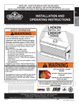
43
9.0 ADJUSTMENT
9.1
PILOT BURNER ADJUSTMENT
EN
Adjust the pilot screw to provide properly sized flame. Turn in a
clockwise direction to reduce the gas flow.
B
A
Check Pressure Readings:
Inlet pressure can be checked by turning screw (A) counterclockwise 2 or 3 turns and then placing pressure gauge tubing
over the test point. Gauge should read as described on the chart
below. Check that main burner is operating on “HI”.
Outlet pressure can be checked the same as above using screw
(B). Gauge should read as described on the chart below. Check
that main burner is operating on “HI”.
PILOT SCREW
FLAME SENSOR
3/8” - 1/2”
AFTER TAKING PRESSURE READINGS, BE SURE TO TURN (9.5mm - 12.7mm)
SCREWS CLOCKWISE FIRMLY TO RESEAL. DO NOT OVER
ELECTRODE
TORQUE.
PILOT
BURNER
Leak test with a soap and water solution.
Pressure
Inlet
Outlet
Natural Gas Natural Gas
(inches)
(millibars)
7”
17.4 mb
(min.4.5”)
(min.11.2mb)
3.5”
8.7 mb
Propane
(inches)
13”
(min.11”)
10”
Propane
(millibars)
32.4 mb
(min.27.4mb)
24.9 mb
FLAME MUST ENVELOP
UPPER 3/8” (9.5mm) TO 1/2”
(12.7mm) OF FLAME SENSOR
39.7
9.2
VENTURI ADJUSTMENT
This appliance has an air shutter that has been factory set open according
to the chart below:
Regardless of venturi orientation, closing the air shutter will cause a more
yellow flame, but can lead to carboning. Opening the air shutter will cause a
more blue flame, but can cause flame lifting from the burner ports. The
flame may not appear yellow immediately; allow 15 to 30 minutes for the
final flame colour to be established.
VENTURI
BURNER
AIR
SHUTTER
OPENING
ORIFICE
AIR SHUTTER ADJUSTMENT MUST ONLY BE DONE BY A QUALIFIED
INSTALLER!
49.1
VENTURI ADJUSTMENT CHART
FUEL
CHD4
CHD4G
NG
1/16” (1.6mm)
1/16” (1.6mm)
LP
5/16” (7.9mm)
5/16” (7.9mm)
W415-1150 / 03.07.13


![Manuel pour foyer HD4 de Napoléon [11,84 Mo]](http://vs1.manualzilla.com/store/data/006322059_1-bf1f6de6b3720587457ff5a521e80257-150x150.png)