1
63230-301-200C1
10/2002
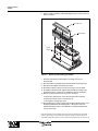
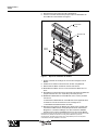
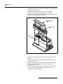
6. Pull the module straight up until it disengages from the circuit monitor, as
shown in Figure 1.
Terminal cover
CVM module
Circuit
monitor
Figure 1:
Removing and installing the module
7. Align the replacement module with the mounting holes on the
circuit monitor.
8. Seat the module, and tighten the three Allen-head screws until snug.
9. Reconnect the voltage and current input wires.
10. Re-install the fuses to the PT, and reconnect the CT and PT leads.
11. Re-install the terminal cover. Tighten the three M3 screws until snug
(maximum torque 1–2 lbs/in [0.113–0.226 Nm]). Do not overtighten.
12. Restore control power to the circuit monitor. To do this:
a. Reconnect control power to the circuit monitor and I/O devices.
b. Remove the short on the CT shorting block.
c. Re-install the voltage input fuses.
13. Run the Wiring Error Test to verify that the module is wired properly. From
the display Main Menu select Diagnostics > Wiring Error Test. For
detailed instructions, refer to the installation manual that shipped with
your circuit monitor.
Electrical equipment should be installed, operated, serviced, and maintained only by qualified
personnel. This document is not intended as an instruction manual for untrained persons. No
responsibility is assumed by Square D for any consequences arising out of the use of this manual.
Class No. 3020
© 2002 Schneider Electric
All Rights Reserved