1
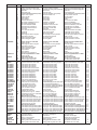
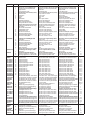
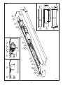
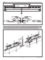
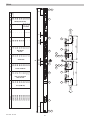
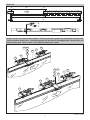
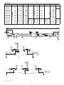
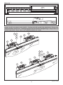
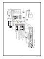
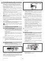
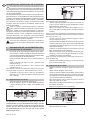
KIT TEN
IP1706 - rev. 2007-07-12
I
GB
DITEC S.p.A.
Via Mons. Banfi, 3 - 21042 Caronno Pertusella (VA) - ITALY
Tel. +39 02 963911 - Fax +39 02 9650314
www.ditec.it - [email protected]
Manuale di assemblaggio
per porte scorrevoli.
Assembly handbook for
sliding doors.
F
Manuel pour l’assemblage
pour portes coulissantes.
D
Zusammenbauanleitung
für Schiebtürantrieb.
E
Manual de ensemblaje
para puertas correderas.
P
Manual de assemblagem
para portas deslizantes.
CODE
KTEN1
REF
1
2
3
4
5
6
7
8
9
10
11
12
13
KTENGCL
KTENCLS
TENGP
TENSI
V2172N33
V2172N44
V2172N66
V2036N33
V2036N44
V2036N66
V2037G33
V2037G44
V2037G66
V2037N33
V2037N44
V2037N66
RCG8M1050
0K69554822N
0K5739612
0K55886
0K55888
CV01
0KP851B
VSP14V25
TENAL
TENAC30
TENA35F
4
10
11
12
13
5
6
4
14
15
16
17
17
17
18
18
18
19
19
19
19
19
19
20
21
22
-
K1356G30
K1356G60
K1356N30
K1356N60
KAC
-
V2995G30
V2995G60
V2995N30
V2995N60
K3016
-
TENRP
TEN L
LOKSBM
TENAB
0KP515AB
0KP366
24
25
-
KIT TEN - IP1706
DESCRIZIONE
DESCRIPTION
DESCRIPTION
Componenti fissi 1 anta:
Gruppo comando trazione TEN
Scheda base diram. comandi DIR
Staffe DIR
Fotocellula (Cel)
Scheda amplificatore fotocellule (CelAS)
Gruppo rinvio cinghia
Gruppo carrello
Tappo battuta
Fermo battuta
Coperchio fermacavi
Manuale di installazione ed uso
Manuale di assemblaggio
Manuale installazione DIR
Etichetta senso di apertura
Etichetta serie automazione
Cavo VDE
Cavo comandi unificato
Testata DX
Testata SX
Staffa supporto attacco cinghia
Staffa attacco cinghia
Piastra bloccaggio cinghia
Piastra fissaggio cinghia
Kit standard for 1 wing:
Control and drive unit TEN
Expanded connecting base board DIR
DIR bracket
Photocell (Cel)
Photocell amplifier card (CelAS)
Belt transmission unit
Carrier unit
Rabbed plug
Rabbed lock
Wire bracket
Installation handbook
Assembly handbook
Installation manual for DIR
Opening direction label
Automation model label
VDE cable
Standard control cable
Right housing head
Left housing head
Belt coupling mounting bracket
Belt attachment bracket
Belt locking plate
Belt fixing plate
Composants fixes 1 battant:
Groupe commande et de traction TEN
Paltine base raccordement élargie DIR
Bride DIR
Photocellula (Cel)
Fiche amplificateur photocellule (CelAS)
Groupe renvoi courroie
Groupe chariot
Butée chariot
Butée
Couvercle serre-câbles
Manuel d’installation
Manuel pour l’assembalge
Manuel d’installation pour DIR
Etiquette sens ap. battant
Etiquette sèrie automatisme
Câble VDE
Câble commandes normalisé
Extrémités caisson droite
Extrémités caisson gauche
Etrier de support attache courroie
Bride courroie
Plaque blocage courroie
Plaque de fixation courroie
Gruppo carrelli 2. anta TEN
Gruppo carrello
Staffa supporto attacco cinghia
Staffa attacco cinghia
Piastra bloccaggio cinghia
Piastra fissaggio cinghia
Tappo battuta
Fermo battuta
Etichetta senso di apertura
Carrello supplementare >1600
Gruppo carrello
Kit giunzione profili
Piatto giunzione profili TEN
Piatto fissaggio profili TEN
Cassonetto e carter
Supporto intermedio carter TEN
Profilo guida TEN naturale
Profilo guida TEN naturale
Profilo guida TEN naturale
Profilo cassonetto TEN naturale
Profilo cassonetto TEN naturale
Profilo cassonetto TEN naturale
Profilo carter TEN grezzo
Profilo carter TEN grezzo
Profilo carter TEN grezzo
Profilo carter TEN naturale
Profilo carter TEN naturale
Profilo carter TEN naturale
Cinghia di trasmissione 8M10
Kit viti autof. TPS 4.8x22 nera
Kit viti TE M6x12 zincate
Kit dadi M6 normali zincati
Kit dadi M8 normali zincati
Kit viti TC M6x10 zincate
Kit guarnizione carter
Spazzolini di tenuta H14
Coppia attacco lungo Al - PAM35
Coppia attacco corto AC - PAM16/30
Coppia staffe PAM35F
Attacchi anta in cristallo
Attacco anta cristallo naturale 3000
Attacco anta cristallo naturale 6050
Attacco anta cristallo grezzo 3000
Attacco anta cristallo grezzo 6050
Kit accessori per AC1356
Attacchi anta intelaiata
Profilo attacco anta generica grezzo
Profilo attacco anta generica grezzo
Profilo attacco anta generica naturale
Profilo attacco anta generica naturale
Coppia piatto fiss. anta generica
Accessori
Kit carrello pesante
Dispositivo di blocco
Sblocco supplementare
Antipanico a batteria
Pattino guida anta intelaiata TEN
Pattino guida anta cristallo TEN
2nd door carrier unit TEN
Carrier unit
Belt coupling mounting bracket
Belt attachment bracket
Belt locking plate
Belt fixing plate
Rabbed plug
Rabbed lock
Opening direction label
Additional carriers >1600
Carrier unit
Section jointing kit
TEN section jointing plate
TEN section fixing plate
Casing and cover
Intermediate TEN casing support
TEN natural guide profile
TEN natural guide profile
TEN natural guide profile
TEN natural casing profile
TEN natural casing profile
TEN natural casing profile
TEN rough cover profile
TEN rough cover profile
TEN rough cover profile
TEN natural cover profile
TEN natural cover profile
TEN natural cover profile
Driving belt 8M10
Set blackself-tapping screws TPS 4.8x22
Set of galvanized TE M6x12
Set of standard galvanized nuts M6
Set of standard galvanized nuts M8
Set of galvanized TC M6x10
Casing seal kit
Seal brushes H14
Pair of long coupling AL
Pair of short coupling AC
Pair of coupling PAM35F
Glass door attachment
Natural glass door attachment 3000
Natural glass door attachment 6050
Rought glass door attachment 3000
Rought glass door attachment 6050
AC1356 accessories
Framed wing attachment
Rough gen. door attachment edge
Rough gen. door attachment edge
Natural gen. door attachment edge
Natural gen. door attachment edge
Pair of fixing plates generic door wing
Accessories
TEN heavy carriage kit
Lock device
Supplementary antipanic
Battery antipanic
Sliding guide for framed door TEN
Sliding guide for glass door TEN
Groupe chariot 2 battant TEN
Groupe chariot
Etrier de support attache courroie
Bride courroie
Plaque blocage courroie
Plaque de fixation courroie
Butée chariot
Butée
Etiquette sens ap. battant
Chariot supplémentaires >1600
Groupe chariot
Kit jonction profils
Plat de jonction profils TEN
Plat de fixation profils TEN
Caisson et carter
Support intermédiaire carter TEN
Profil guide TEN naturel
Profil guide TEN naturel
Profil guide TEN naturel
Profil caisson TEN naturel
Profil caisson TEN naturel
Profil caisson TEN naturel
Profil carter TEN brut
Profil carter TEN brut
Profil carter TEN brut
Profil carter TEN naturel
Profil carter TEN naturel
Profil carter TEN naturel
Courroie de transmission 8M10
Kit vis autot. TPS 4.8x22 noire
Kit vis TE M6x12 zinguées
Kit écrous M6 standard zinguées
Kit écrous M8 standard zinguées
Kit vis TC M6x10 zinguées
Kit joint carter
Brosses d’étanchéité H14
Paire de fixation longues AL
Paire de fixation courtes AC
Paire de fixation PAM35F
Fixation battant a verre
Fixation battant a verre naturel 3000
Fixation battant a verre naturel 6050
Fixation battant a verre brut 3000
Fixation battant a verre brut 6050
Accessoire AC1356
Fixation vantail sur châssis
Profil brut fixation du vantail générique
Profil brut fixation du vantail générique
Profil naturel fixation du vantail générique
Profil naturel fixation du vantail générique
Deux plats fixation vantail générique
Accessoires
Kit chariot lourd
Dispositiv de blocage
Déblocage supplémentaire
Antipanique à batterie
Rail battant à châssis TEN
Rail battant en verre TEN
2
QT
1
1
2
1
1
1
2
2
2
14
1
1
1
2
1
1
1
1
1
1
1
1
1
2
1
1
1
1
2
2
1
2
10
10
1
3.3 m
4.4 m
6.6 m
3.3 m
4.4 m
6.6 m
3.3 m
4.4 m
6.6 m
3.3 m
4.4 m
6.6 m
50 m
500
1000
1000
1000
500
200 m
2.5 m
1
1
1
3m
6m
3m
6m
1
3m
6m
3m
6m
1
1
1
1
1
10
10
CODE
KTEN1
REF
1
2
3
4
5
6
7
8
9
10
11
12
13
KTENGCL
KTENCLS
TENGP
4
10
11
12
13
5
6
4
14
15
TENSI
V2172N33
V2172N44
V2172N66
V2036N33
V2036N44
V2036N66
V2037G33
V2037G44
V2037G66
V2037N33
V2037N44
V2037N66
RCG8M1050
0K69554822N
0K5739612
0K55886
0K55888
CV01
0KP851B
VSP14V25
TENAL
TENAC30
TENA35F
16
17
17
17
18
18
18
19
19
19
19
19
19
20
21
22
-
K1356G30
K1356G60
K1356N30
K1356N60
KAC
-
V2995G30
V2995G60
V2995N30
V2995N60
K3016
-
TENRP
TEN L
LOKSBM
TENAB
0KP515AB
0KP369
24
25
-
BESCHREIBUNG
DESCRIPCION
DESCRIÇÃO
Grundbausatz 1 Flügel:
Steuerungs- und Antriebseinheit
Erweiterte Anschlußplatine DIR
Bügel für DIR
Lichtschranken (Cel)
Verstärkerkarte für Photozellen (CelAS)
Umlenkeinheit
Laufwagen
Deckel
Halter
Kabelhalter
Installationhandbuch
Zusammenbauanleitung
Montagehandbuch für DIR
Aufkleber Öffnungrichtungs des Flügels
Aufkleber Antriebskennzeichnung
VDE-Kabel
Genormtes Steuerkabel
Seitendeckel rechts
Seitendeckel links
Zahnriemenanschluss
Riemenanschlussbügel
Riemenbefestigungsplatte
Riemenanschlußplatte
Componentes fijos para 1 hoja:
Grupo de mando y de tracción TEN
Tarjeta de conexiòn ampliada DIR
Brida DIR
Fotocélula (Cel)
Ficha amplificador fotocélulas (CelAS)
Grupo reenvìo correa
Grupo carro
Tope carro
Tope
Tapa sujeta-cables
Manual de instalaciòn
Manual de ensablaje
Manual para la instalaciòn DIR
Etiqueta sentido apertura hoja
Etiqueta serie automatizaciòn
Cable VDE
Cable mandos estàndar
Extremos cajòn derecho
Extremos cajòn izquierdo
Estribo de soporte empalme correa
Brida de conexiòn correa
Placa bloqueo correa
Placa de conexiòn correa
Componentes fixos 1 portinhola:
Grupo comando de tracção TEN
Placa base de transm. comandos DIR
Suporte DIR
Foto-célula (Cel)
Placa amplificador fotocélulas (CelAS)
Grupo intermediário da correia
Grupo carro
Tampa de batida
Bloqueador de batida
Tampa do prensador de cabos
Manual de instalação e uso
Manual de montagem
Manual de instalação DIR
Etiqueta do sentido de abertura
Etiqueta da série de automação
Cabo VDE
Cabo dos comandos unificado
Cabeça DIR
Cabeça ESQ
Suporte de sustentação do engate correia
Suporte do engate correia
Chapa de bloqueio da correia
Chapa de fixação da correia
Laufwagen 2. Zusatzflügel TEN
Laufwagen
Zahnriemenanschluss
Riemenanschlußkasten
Riemenbefestigungsplatte
Riemenanschlußplatte
Deckel Anschlag
Halter Anschlag
Aufkleber Öffnungrichtungs des Flügels
Zusatzwagen für Flügel >1600
Laufwagen
Bausatz Profilverbindungen
Verbindungsplatte für TEN-Profile
Befestigungsplatte für TEN-Profile
Laufprofil und Haubenprofil
Haubenstütze
Laufprofil eloxiert
Laufprofil eloxiert
Laufprofil eloxiert
Komponententräger eloxiert
Komponententräger eloxiert
Komponententräger eloxiert
Haubenprofil roh
Haubenprofil roh
Haubenprofil roh
Haubenprofil eloxiert
Haubenprofil eloxiert
Haubenprofil eloxiert
Antriebsriemen 8M10
Satz Schrauben selbstsch. TPS 4.8x22
Satz Schrauben TE M6x12 verzinkt
Satz Muttern M6 normal verzinkt
Satz Muttern M8 normal verzinkt
Satz Schrauben TC M6x10 verzinkt
Satz Gehäusedichtung
Dichtbürste
PAM35 Lange Flügelkupplung
PAM16-30 Kurze Flügelkupplung
Flügelkupplung PAM35F
Anschlußprofil für Ganzglasflügel
Glasflügelanschluss roh
Glasflügelanschluss roh
Glasflügelanschluss eloxiert
Glasflügelanschluss eloxiert
AC1356 Zubehör
Anschlußprofil für Rahmenflügel
Anschlußprofil Standard-Flügel roh
Anschlußprofil Standard-Flügel roh
Anschlußprofil Standard-Flügel eloxiert
Anschlußprofil Standard-Flügel eloxiert
Paar Befestigungsplatten Standard-Flügel
Zubehör
Kit verstärkte Laufwagen
Verriegelung mit Handentriegelung
Zusätzliche Handentriegelung
Akkupack
Bodenführung für Rahmenflügel
Bodenführung für Ganzglasflügel
Grupo carros segunda hoja TEN
Grupo carro
Estribo de soporte empalme correa
Brida de conexiòn correa
Placa bloqueo correa
Placa de conexiòn correa
Tope carro
Tope
Etiqueta sentido apertura hoja
Carros suplementarios >1600
Grupo carro
Equipo empalme perfiles
Plato de empalme perfiles TEN
Plato de fijación perfiles TEN
Caja y càrter
Soporte intermedio càrter TEN
Perfil guía TEN natur
Perfil guía TEN natur
Perfil guía TEN natur
Perfil caja TEN natur
Perfil caja TEN natur
Perfil caja TEN natur
Perfil càrter TEN bruto
Perfil càrter TEN bruto
Perfil càrter TEN bruto
Perfil càrter TEN natur
Perfil càrter TEN natur
Perfil càrter TEN natur
Correa de transmisiòn 8M10
Kit tornillos autor. TPS 4.8x22 negro
Kit tornillos TE M6x12 galvanizados
Kit tuercas M6 estàndards galvan.
Kit tuercas M8 estàndards galvan.
Kit tornillos TC M6x10 galvanizado
Kit junta càrter
Cepillos de estanqueidad H14
Par de fijaciòn largo AL
Par de fijaciòn corto AC
Par de fijaciòn PAM35F
Fijaciòn hoja en vidrio
Fijaciòn hoja en vidrio natur 3000
Fijaciòn hoja en vidrio natur 6050
Fijaciòn hoja en vidrio bruto 3000
Fijaciòn hoja en vidrio bruto 6050
Accessorios AC1356
Fijación hoja en el marco
Perfil fijaciòn puerta genérica bruto
Perfil fijaciòn puerta genérica bruto
Perfil fijaciòn puerta genérica natural
Perfil fijaciòn puerta genérica natural
Par plato fijaciòn puerta genérica
Accessorios
Kit carro pesado
Dispositivo de bloqueo
Desbloqueo suplementario
Antipànico de baterìa
Rieles guìa hoja en bastidor TEN
Rieles guìa hoja en vidrio TEN
Grupo dos carros 2. portinhola TEN
Grupo carro
Suporte de sustentação do engate correia
Suporte do engate correia
Chapa de bloqueio da correia
Chapa de fixação da correia
Tampa de batida
Bloqueador de batida
Etiqueta do sentido de abertura
Carro suplementar >1600
Grupo carro
Kit de junção dos perfis
Prato de junção dos perfis TEN
Prato de fixação dos perfis TEN
Gaveta e cárter
Sustentação do intermédio cárter
Perfil da guia TEN natural
Perfil da guia TEN natural
Perfil da guia TEN natural
Perfil da gaveta TEN natural
Perfil da gaveta TEN natural
Perfil da gaveta TEN natural
Perfil do cárter TEN bruto
Perfil do cárter TEN bruto
Perfil do cárter TEN bruto
Perfil do cárter TEN natural
Perfil do cárter TEN natural
Perfil do cárter TEN natural
Correia de transmissão 8M10
Kit parafusos autoros. TPS 4.8x22 preto
Kit parafusos TE M6x12 galvan.
Kit de porcas M6 normais galvanizadas
Kit de porcas M8 normais galvanizadas
Kit de parafusos CC M6x10 galvan.
Kit de guarnição do cárter
Escovas de retenção H14
Binário de engate longo AL PAM35
Binário de engate curto AC PAM16/30
Par estribos PAM35F
Engates da portinhola de vidro
Engate da portinhola vidro nat. 3000
Engate da portinhola vidro nat. 6050
Engate da portinhola de vidro bruto 3000
Engate da portinhola de vidro bruto 6050
Acessórios AC1356
Engates da portinhola fixada na estrutura
Perfil engate portinhola genérica bruto
Perfil engate portinhola genérica bruto
Perfil engate portinhola genérica natural
Perfil engate portinhola genérica natural
Par chapa fix. portinhola genérica
Acessórios
Kit carro pesado
Dispositivo de bloqueio
Desbloqueio suplementar
Anti-pânico com bateria
Prato guia portinh. fixada na estrutura
Prato guia da portinhola de vidro
3
QT
1
1
2
1
1
1
2
2
2
14
1
1
1
2
1
1
1
1
1
1
1
1
1
2
1
1
1
1
2
2
1
2
10
10
1
3.3 m
4.4 m
6.6 m
3.3 m
4.4 m
6.6 m
3.3 m
4.4 m
6.6 m
3.3 m
4.4 m
6.6 m
50 m
500
1000
1000
1000
500
200 m
2.5 m
1
1
1
3m
6m
3m
6m
1
3m
6m
3m
6m
1
1
1
1
1
10
10
KIT TEN - IP1706
KIT TEN - IP1706
4
4
9
5
6
18
14
15
25
19
3
20
25
4
15
14
5
6
24
24
16
7
2
L
40
≤4
19
18
17
m
0m
1
10
17
LT-7
LT-6
LT-6
18
19
500
8
10
Ø
30
Ø
7
16
60
TEN
101
Fig. 1
TEN-2
S
S
PL
OPEN
OPEN
LM
LM
10
10
LT
OPEN
OPEN
Gruppo carrello con attacco anta intelaiata - Carriage unit with framed wing attachment - Groupe
chariot avec fixation vantail sur châssis - Laufwagengruppe mit Anschluß für Rahmenflügel - Grupo carro con fijación hoja en el marco - Grupo carro com engate portinhola encaixilhada
4
4
11
13
11
10
12
4
21
4
12
10
13
21
21
5
KIT TEN - IP1706
KIT TEN - IP1706
6
OPEN
LM
4
25
LT
140
140
11
12 13
235
285
335
385
435
485
535
635
735
835
10
A
10
11
24
C1 = 100
LT
2000
2200
2400
2600
2800
3000
3200
3600
4000
4400
13 12
LT=PL+2LM+20
140
4
16
520
570
620
670
720
770
820
920
1020
1120
LM
A=LM-285
3
940
1040
1140
1240
1340
1440
1540
1740
1940
2140
PL
25
LM
135
185
235
285
335
385
435
535
635
735
4
B
B=LM-385
B≥150
6
5
A
Code
TEN2O20
TEN2O22
TEN2O24
TEN2O26
TEN2O28
TEN2O30
TEN2O32
TEN2O36
TEN2O40
TEN2O44
4
2
140
C2 = 5
C1
100
100
100
100
100
100
100
-
OPEN
5
C2
5
5
5
[15]
Yes
Yes
Yes
Yes
1
LB
2420
3140
3340
3540
3740
3940
4140
4540
4940
5340
B
(1)
Note
(1)
6
5
TEN-2
LB=2(LT-A-B-160)
LT≥3200
LM= (LT+2S-20)/4
LM= PL/2+S
PL= (2LM-2S)
TEN-1 DX
S
PL
S
OPEN
LM
10
10
LT
Gruppo carrello con attacco anta cristallo - Carriage unit with crystal wing attachment - Groupe chariot avec fixation vantail verre - Laufwagengruppe mit Anschluß für Ganzglasflügel - Grupo carro con
fijación hoja cristal - Grupo carro com engate portinhola em cristal
13
12
11
22
4
20
22
10
4
N
E
OP
12 13
11
10
4
22
20
22
4
4
EN
OP
7
KIT TEN - IP1706
TEN-1 DX
3200
3600
4000
4400
B
40
150
150
340
440
540
640
740
840
940
430
530
630
730
D
147
147
147
147
147
147
147
147
147
147
17
17
17
17
[15]
Yes
Yes
Yes
Yes
LB
LB=2(LT-A-B-160)
2
2
2
2
2
2
2
2
2
2
660
760
860
960
LT≥3200
1615
1815
2015
2215
A
1200
1400
1600
1800
2000
2200
2400
2600
2800
3000
B=LM-575 B≥150
LT
B=LM/2-338
1515
1715
1915
2115
615
715
815
915
1015
1115
1215
1315
1415
1515
A=LM/2-148
LM=PL+2S
PL=LM-2S
TEN1O32
TEN1O36
TEN1O40
TEN1O44
LM
515
615
715
815
915
1015
1115
1215
1315
1415
LT=PL+LM+S+20
PL
LM=(LT+S-20)/2
Code
TEN1O12
TEN1O14
TEN1O16
TEN1O18
TEN1O20
TEN1O22
TEN1O24
TEN1O26
TEN1O28
TEN1O30
2000
2180
2580
2600
2800
3000
3200
3400
3600
3800
3900
4300
4700
5100
Note
(1-2)
(1)
(3)
(3)
(3)
(3)
LT
D
5
5
A
B
(2)
24
3
(1)
25
16
2
1
5
6
13 12
11
4
4
10
140
200
OPEN
LM
13 12
11
4
4
10
4
(3)
140
200
LM
KIT TEN - IP1706
8
OPEN
TEN-1 SX
S
S
PL
OPEN
LM
10
10
LT
Gruppo carrello con attacco anta cristallo - Carriage unit with crystal wing attachment - Groupe chariot avec fixation vantail verre - Laufwagengruppe mit Anschluß für Ganzglasflügel - Grupo carro con
fijación hoja cristal - Grupo carro com engate portinhola em cristal
22
13 12
11
4
20
10
22
4
12 13
EN
OP
11
10
20
22
4
22
4
22
4
EN
OP
9
KIT TEN - IP1706
TEN-1 SX
A
2
2
2
2
2
2
2
2
2
660
760
860
960
B
200
260
400
500
600
700
800
900
1000
430
530
630
730
[15]
-
LB
LB=2(LT-A-B-160)
1400
1600
1800
2000
2200
2400
2600
2800
3000
3200
3600
4000
4400
LT≥3200
LT
B=LM-575 B≥230
715
815
915
1015
1115
1215
1315
1415
1515
1615
1815
2015
2215
B=LM/2-378
1515
1715
1915
2115
LM
A=LM/2-148
PL=LM-2S
TEN1O32
TEN1O36
TEN1O40
TEN1O44
615
715
815
915
1015
1115
1215
1315
1415
LT=PL+LM+S+20
PL
LM=(LT+S-20)/2
LM=PL+2S
Code
TEN1O14
TEN1O16
TEN1O18
TEN1O20
TEN1O22
TEN1O24
TEN1O26
TEN1O28
TEN1O30
Yes
Yes
Yes
Yes
Note
2080
2360
2480
2680
2880
3080
3280
3480
3680
(1-2)
3900
4300
4700
5100
(3)
(3)
(3)
(3)
LT
B
5
A
D = 17
5
(2)
5
3
16
(1)
25
1
2
24
6
13 12
11
4
4
10
140
OPEN
200
LM
13 12
11
4
OPEN
4
(3)
10
140
200
LM
KIT TEN - IP1706
4
10
11
DIR
J
21 22
R
E
M
O
T
E
COM
SAFETY
DIP
on
TELRS
RF VA VC RP 1 2 3
ENABLE
Converter COME COME
TELR TELR
DMCS
DIR
0CEL1S
PASM24
COMH-K
1A B
OPEN
LAN4S
LAN7S
LAB9
BIXLR22
Uscita / Output 24 V= / 0,5 A +
-
Reset
Esclusione blocco / Lock exclusion
Comune parziale / Partial common
Stop
Sicurezza in chiusura / Closing safety
Sicurezza in apertura / Opening safety
Chiusura / Closing
Apertura lato B / Opening side B
Apertura lato A / Opening side A
Chiusura automatica / Automatic closure
Motor
EL16
29 28 27 9 8 6 4 3B 3A 2 1 0
KIT TEN - IP1706
on
off
OPEN
1 2
DIP
Lock
COME
TELR
DIR
J
IN
SA
POWER
ALARM
TC
COM
Transf.
0 1 2122
1 G141
R1
Fuse
F10A
-
+
+
-
F1
ENC
BAT
~
24 V ~
BL
+
MOT -
12 V
12 V
+
-
N L
230 V~
AVVERTENZE GENERALI PER LA SICUREZZA
Il presente manuale di assemblaggio è rivolto esclusivamente a personale professionalmente competente.
L’assemblaggio, i collegamenti elettrici e le regolazioni devono
essere effettuati nell’osservanza della Buona Tecnica e in ottemperanza alle norme vigenti.
Leggere attentamente le istruzioni prima di iniziare l’assemblaggio del prodotto. Un errato assemblaggio può essere fonte
di pericolo.
I materiali dell’imballaggio (plastica, polistirolo, ecc.) non vanno
dispersi nell’ambiente e non devono essere lasciati alla portata
dei bambini in quanto potenziali fonti di pericolo.
Prima di iniziare l’assemblaggio verificare l’integrità del prodotto.
Prima di collegare l’alimentazione elettrica accertarsi
che i dati di targa siano rispondenti a quelli della rete di
distribuzione elettrica.
Prevedere sulla rete di alimentazione un interruttore/sezionatore onnipolare con distanza d’apertura dei contatti uguale o
superiore a 3 mm. Verificare che a monte dell’impianto elettrico
vi siano un interruttore differenziale e una protezione di sovracorrente adeguati.
Per l’eventuale riparazione o sostituzione dei prodotti dovranno
essere utilizzati esclusivamente ricambi originali.
La manipolazione delle parti elettroniche deve essere
effettuata munendosi di bracciali conduttivi antistatici
collegati a terra.
1.
max 0,5 mm
I
Attenzione: una regolazione non corretta pregiudica il buon
funzionamento dell’automazione.
Verificare, facendo scorrere i carrelli all’interno della guida,
che le ruote siano prive di ammaccature (se le ruote sono
ammaccate sostituirle).
Segnare a matita sul cassonetto le misure A, B, C1, C2 e
D indicate in tabella (oppure ottenute mediante formula).
N.B.: nei casi di automazioni molto piccole il trasformatore e/o
le batterie [25], vanno posizionate all’esterno del cassonetto
(vedi nota 1 e 2).
Inserire all’interno della guida nr. 2 carrelli per anta; se
LM>1600 aggiungere un terzo carrello per anta (nota 3).
Montare le staffe attacco anta sui carrelli (come illustrato
nelle figure) e fissare ai carrelli, nelle posizioni indicate in
tabella, le staffe attacco cinghia e scontro blocco.
Introdurre nr. 15 viti TE M6x12 nell’apposita guida del
cassonetto per il fissaggio dei componenti.
Fissare i componenti: gruppo motore [1], DIR [2], batterie
[25], blocco [24] e rinvio cinghia [3] (senza bloccare) al
cassonetto mediante le viti in dotazione, e seguendo le
misure indicate in tabella.
N.B.: con automazione LT≥3200 fissare la staffa supporto carter
[16].
Posizionare i fermi battuta [6] e i tappi battuta [5] all’interno
della guida.
ASSEMBLAGGIO AUTOMAZIONE
1.1 Procedura di assemblaggio
-
In base al tipo di automazione scelta (TEN2, TEN1-DX,
TEN1-SX), utilizzare la tabella dimensionamenti o le formule indicate per ricavare le misure utili all’assemblaggio
dell’automazione.
Tagliare l’alluminio della guida LT-6 mm come da figura 1.
Tagliare l’alluminio del cassonetto LT-6 mm e forare come
da fig. 1.
Tagliare l’alluminio del carter LT-7 mm e forare come da
fig. 1.
N.B.: pulire l’alluminio da eventuali residui di taglio e in particolare
pulire la guida di scorrimento carrelli.
Agganciare il cassonetto alla guida e fissarlo con i piatti
giunzione [14] e i piatti fissaggio profili [15] ogni 600 - 700
mm.
1.3 Regolazione cinghia
-
-
1.2 Regolazione carrelli
-
Allentare le viti che fissano il gruppo rinvio al cassonetto.
Allentare la staffa attacco cinghia.
Tagliare la cinghia alla misura LB (vedi tabelle), far passare
la cinghia [20] fra la puleggia motore e il rinvio e unirla in
corrispondenza della staffa attacco cinghia (N.B.: tagliare
eventuali eccedenze).
Tirare manualmente tutto il gruppo rinvio verso sinistra e
fissarlo al cassonetto.
Svitare la vite [G] fino a portare la molla alla compressione
di 20÷22 mm.
Bloccare la regolazione con le viti [F].
Allentare la vite di fissaggio eccentrico [1].
Muovere con un cacciavite l’eccentrico [2] in modo da far
alzare o abbassare la ruota [3] come indicato in figura.
2
20
F
3
G
3
1
-
La regolazione va fatta tenendo in appoggio le due ruote laterali
sulla guida di scorrimento inferiore. La ruota centrale non deve
risultare in spinta sulla guida di alluminio superiore ma deve
rimanere ad una distanza massima di circa 0,5 mm, in modo
che il carrello possa scorrere liberamente.
KIT TEN - IP1706
12
LT<2600 = 22 mm
LT≥2600 = 20 mm
Stringere tutte le viti.
Fissare le testate al cassonetto.
2.
CABLATURE ELETTRICHE
-
Collegare mediante gli appositi cablaggi il trasformatore, il motore, l’encoder, le batterie [25] e il blocco [24] al quadro elettrico
(vedi fig. 2).
N.B.: tagliare quando possibile i cablaggi in eccedenza oppure attorcigliare le esuberanze.
Bloccare i cavi mediante i ferma cavi [7] in dotazione.
3.
COLLAUDO AUTOMAZIONE
3.1 Impostazione dei dip-switch
AZIONE
DIP1 = OFF per TEN2 e TEN1-DX
DIP1 = ON per TEN1-SX
DIP2 = OFF per TEN
DIR
DIP1 = ON
DIP2 = OFF
DIP3 = ON per TEN
EFFETTO
- variazione del senso di apertura
- selezione tipo automazione
Attenzione: deve essere impostato DIP2 = OFF
- funzionamento a batteria, se presente, in mancanza di tensione
- con batterie presenti, l’automazione in mancanza di tensione
esegue l’ultima apertura e poi si spegne
- selezione tipo di blocco
Attenzione: deve essere impostato DIP3 = ON
3.2 Collaudo funzionale
Effettuare i collegamenti indicati in fig. 2, chiudere i contatti 41-6, 41-8, 1-9 e collegare la DIR.
Collegare il trasformatore alla rete (230 V~/50 Hz).
Dare i seguenti comandi al quadro elettrico e verificare visivamente l’effetto dei comandi e la linearità della corsa.
AZIONE
EFFETTO
Accensione quadro elettronico
- led verde acceso
Premere il tasto ENABLE per 3 s.
- vengono abilitati i trimmer e i dip-switch
Comando 1-3A (impulsivo)
- manovra di apertura
Comando 1-4 (impulsivo)
- manovra di chiusura
Comando 27-3B (impulsivo)
- manovra di apertura parziale
Chiudere il contatto 1-2
- a seguito di un comando apre, la porta si richiude dopo il
tempo impostato su TC
Comando 41-6 durante l’apertura (apertura contatto)
- riduzione della velocità di apertura negli ultimi 500 mm di
corsa.
Comando 41-8 durante la chiusura (apertura contatto).
- riapertura
Verifica della scheda fotocellule durante la fase di chiusura: - interrompendo l’allineamento ottico tra TX ed RX durante la
chiusura, l’anta deve riaprire
- inserire la scheda CelAS su DIR
- collegare la CelPR
Comando 1-9 (apertura contatto)
- arresto per la durata del comando
Comando 1-29
- reset, azzeramento dati encoder
3.3 Prova di caos
Dare continui comandi apre e chiude in modo che l’anta o le ante inverta in continuazione senza fermarsi (per almeno 1 minuto).
L’automazione non deve perdere il controllo della posizione, non deve sbattere e non devono verificarsi anomalie logiche.
13
KIT TEN - IP1706
I
I
AZIONE
3.4
Verifica dei trimmer
Regolazione trimmer TC
Regolazione trimmer R1
Regolazione trimmer RF
Regolazione trimmer VA
Regolazione trimmer VC
Regolazione trimmer RP
EFFETTO
- variazione del tempo di chiusura automatica
- variazione della spinta sugli ostacoli
- variazione della forza motore
- variazione della velocità di apertura
- variazione della velocità di chiusura
- variazione dell’apertura parziale
3.5 Settaggio di default
Al termine del collaudo impostare la seguente configurazione:
tutti i trimmer al massimo;
DIP1 è dipendente dal senso di apertura della porta;
se le batterie sono presenti devono essere scollegate, verificare che il quadro elettrico non sia alimentato da esse (premere
il comando 1-29 di RESET).
N.B.: si consiglia di non abilitare i trimmer e i dip-switch presenti sul DIR, lasciando attive le impostazioni di fabbrica. Nel caso
si vogliano usare le regolazioni presenti sul DIR, seguire le indicazioni presenti nel manuale di installazione BIS (oppure nel
manuale DIR).
3.6 Verifiche generali
-
Verificare la lunghezza del cassonetto, la larghezza del vano passaggio e la larghezza anta.
Allegare il cavo di alimentazione e il cavo comandi completi dei relativi passacavi.
Applicare la guarnizione carter.
Effettuare un controllo generale (tensione cinghia, bloccaggio viti, ecc.).
Compilare e applicare l’etichetta con marcatura CE.
LEGENDA
PL
LM
LT
LB
S
Vano passaggio orizzontale
Lunghezza anta mobile
Lunghezza totale automazione
Lunghezza cinghia
Sormonto (nominale=50; min=25; max=secondo le esigenze)
NOTE
(1)
(2)
(3)
Trasformatore esterno
Batterie esterne
Se LM>1600 aggiungere terzo carrello [4]
Tutti i diritti sono riservati
I dati riportati sono stati redatti e controllati con la massima cura. Tuttavia non possiamo assumerci alcuna responsabilità per
eventuali errori, omissioni o approssimazioni dovute ad esigenze tecniche o grafiche.
KIT TEN - IP1706
14
GENERAL SAFETY PRECAUTIONS
GB
1.
max 0,5 mm
This assembling manual is intended for professionally
competent personnel only.
The assembling, the electrical connections and the settings
must be completed in conformity with good workmanship and
with the laws in force. Read the instructions carefully before
beginning assembling the product. Incorrect assembling may
be a source of danger.
Packaging materials (plastics, polystyrene, etc) must not be allowed to litter the environment and must be kept out of the reach
of children for whom they may be a source of danger.
Before beginning the assembling check that the product is in
perfect condition.
Before connecting to the mains check that the rating is
correct for the destination power requirements.
A multipolar isolation switch with minimum contact gaps of 3 mm
must be included in the mains supply. Check that upstream of
the electrical installation there is an adequate differential switch
and a suitable circuit breaker.
For repairs or replacements of products only original spare parts
must be used.
It is recommended that antistatic conductive earthed arm
bands be worn when manipulating electronic parts.
Attention: a wrong adjustment can prevent the automation from
working properly.
Slide the carriages in the slideways to check that the
wheels are not indented (if they are, change them).
Mark measurements A, B, C1, C2, and D as shown in the
table (or as calculated according to the formula) on the
box with a pencil.
Note: for very small automatic systems, position the transformer
and/or the batteries [25] outside the box (see note 1, 2).
Fit two carriages for each door wing. If LM>1600, add a
third carriage for each wing (see note 3).
Fit the wing anchoring brackets onto the carriages (as
shown in figures) and secure the belt anchoring brackets
and block striker to the carriages.
Insert 15 hexagonal-head screws M6x12 into the appropriate guide in the box for securing the various components.
Secure the various components, the motor [1], DIR [2], the
batteries [25], the block [24], and the belt idler [3] (without
tightening) to the box by means of the screws provided,
and respecting the measurements indicated in the table.
Note: in the LT≥3200 automation system, secure the casing
mounting bracket [16].
Position the stops [6] and stop caps [5] inside the slideway.
ASSEMBLING THE AUTOMATIC SYSTEM
1.1 Assembling procedure
-
Depending on the type of system to be assembled (TEN2,
TEN1-DX, TEN1-SX), refer to the relevant sizing tables (or
to the specified formulas) to work out the useful measurements for assembling the automatic system.
Cut the aluminium of the guide LT-6 mm as shown in fig. 1.
Cut the aluminium of the box LT-6 mm and drill a hole as
shown in fig 1.
Cut the aluminium of the casing LT-7 mm and drill a hole
as shown in fig. 1.
Note: clear the aluminium of any burrs and in particular clean
the carriage slideways.
Hook up the box to the guide and secure it by means of
jointing plates [14] and section fixing plates [15] (each 600
- 700 mm).
1.3 Adjusting the belt
-
1.2 Carriage adjustment
-
Loosen the eccentric fastening screw [1].
Use a screwdriver to move the eccentric [2] so as to raise
or lower the wheel [3] as it is shown in the figure.
2
-
Loosen the screws which secure the idler unit to the
box.
Loosen the belt anchoring bracket.
Cut the belt to size LB (see tables), route the belt [20]
between the motor pulley and the idler, and join the two
ends together at the belt anchoring bracket (Note: cut any
excess lengths).
Manually pull the idler unit to the left and secure it to the
box.
Loosen screw [G] to load the spring to 20÷22 mm.
Lock the belt in this position with screws [F].
3
20
F
1
The adjustment shall be made with the two wheels on the lower
sliding track. The central wheel shall not push onto the upper
aluminium track, but there shall be a maximum distance of 0.5
mm between them, so that the trolley can slide smoothly.
G
3
-
15
LT<2600 = 22 mm
LT≥2600 = 20 mm
Tighten all screws.
Secure the heads to the box.
KIT TEN - IP1706
GB
2.
WIRING
-
Wire up the transformer, the motor, the encoder, the batteries [25] and the lock [24] to the electric board by means of the
appropriate wires (see fig. 2).
Note: wherever possible, cut off or twist up any excess lengths of wire.
Secure the wires by means of the cable clamps [7] provided.
3.
TESTING THE AUTOMATIC SYSTEM
3.1 Checking the dip-switches
ACTION
DIP1 = OFF for TEN2 and TEN1-DX
DIP1 = ON for TEN1-SX
DIP2 = OFF for TEN
DIR
DIP1 = ON
DIP2 = OFF
DIP3 = ON for TEN
OUTCOME
- changing the opening direction
- automation type selection
Warning: DIP2 must be set to OFF
- battery function, if present, in the event of blackout
- in the event of blackout, the automation with the batteries present performs the last opening manoeuvre and then switches
off.
- block type selection
Warning: DIP3 must be set to ON
3.2 Functional test
Wire up as shown in fig. 2, close the contacts 41-6, 41-8, 1-9 and connect the DIR.
Connect the transformer to mains (230 V~/50 Hz).
Give the following commands to the electric board and visually check for correct response and straight and smooth running.
ACTION
Electric board turned on
Press button ENABLE for 3 s.
Command 1-3A (pulse contact)
Command 1-4 (pulse contact)
Command 27-3B (pulse contact)
Closing a 1-2 contact
Command 41-6 during opening (opening contact)
Command 1-8 during closing (opening contact)
Check for the photocell card during the closing phase:
- insert the CelAS card on DIR
- connect the CelPR
Command 1-9 (opening contact)
Command 1-29
OUTCOME
- green LED on
- trimmers and dip-switches are enabled
- opening manoeuvre
- closing manoeuvre
- partial opening manoeuvre
- after an open command the door closes after the elapsing of
the time set on TC
- reduce in the last 500 mm of the door stroke when the contact is opened.
- re-opening
- the wing should reopen when the optic alignment between
TX and RX is interrupted during the closing operation
- stop throughout duration of command
- reset, encoder zero setting
3.3 Chaos test
Send repeated open and close commands so as to cause the wing or wings to continuously reverse direction of movement without
stopping (for at least 1 minute). Check that the automation system does not fail to appropriately keep wing position under control
nor cause the wing or wings to slam, and that no logic malfunction occurs.
KIT TEN - IP1706
16
3.4 Checking the trimmers
TC trimmer adjustment
R1 trimmer adjustment
RF trimmer adjustment
VA trimmer adjustment
VC trimmer adjustment
RP trimmer adjustment
ACTION
-
variation
variation
variation
variation
variation
variation
of
of
of
of
of
of
the
the
the
the
the
the
GB
OUTCOME
automatic closure time
force on obstacles
motor power
opening speed
closing speed
partial opening
3.5 Default setting
Upon the testing is completed, set as follows:
all trimmers to maximum.
DIP1 depends on the opening direction of the door;
disconnect batteries (if installed), checking that the electric board is not being powered by them (press RESET command
1-29).
Note: it is advisable not to enable the trimmers and the dip-switches on the DIR, leaving the default settings active. If the user wishes
to use the adjustments on the DIR, closely adhere to the instructions given in the installation manual BIS (or in the DIR manual).
3.6 General controls
-
Control the length of the casing, the passage width and the width of the leaf.
Tie the power supply cable and command cables with related channels.
Apply the casing seal.
Perform a general check (belt tension, screw tightness, etc).
Fill-in and apply the CE label.
CAPTION
PL
LM
LT
LB
S
Horizontal passageway
Mobile wing lenght
Overall automatic system lenght
Belt lenght
Overlap (nominal = 50; min = 25; max = as the case requires)
NOTE
(1)
(2)
(3)
External transformer
External batteries
If LM>1600 add the third carriage [4]
All right reserved
All data and specifications have been drawn up and checked with the greatest care. The manufacturer cannot however take any
responsibility for eventual errors, ommisions or incomplete data due to technical or illustrative purposes.
17
KIT TEN - IP1706
CONSIGNES GENERALES DE SECURITE
Cette notice assemblage est destinée exclusivement aux
professionels qualifiès
Assemblage, le raccordement électrique et les réglages doivent
être effectuée selon les régles de Bonne Tecniques er respecter
la réglementation en vigueur. Lire attentivement les instructions
avant de procéder à l’assemblage du produit. Une assemblage
erronée peut être source de danger.
Les materiaux de l’emballage (plastique, polystyréne, etc) ne
doivent pas être abandonnées dans la nature et ne doivent pas
être laissés à la portée des enfants, car ils sont une source potentielle de danger. Avant de procéder à l’assemblage, vérifier
l’integrité du produit.
Avant de procéder au raccordement électrique, s’assurer
que les données de la plaquette signalétique correspondent à celles du réseau d’alimentation électrique. Prévoir sur
le réseau d’alimentation un dispositif de coupure omnipolaire
avec une distance d’ouverture des contacts égale ou supérieure
à 3 mm. Vérifier qu’en amont de l’installation électrique il y ait
un interrupteur différentiel ainsi qu’une protection contre des
surchanges de courant adèquate. En cas de réparation ou de
remplacement des produits, sed pièces de rechange originales.
impérativement être utilisées.
La manipulation des parties électroniques doit être effectuée en mettant des bracelets conducteurs antistatiques
reliés à la terre.
1.
max 0,5 mm
F
Attention: un réglage incorrect compromet le bon fonctionnement
de l’automatisation.
Vérifier, en faisant coulisser les chariots à l’intérieur du
rail, que les roues ne sont pas bosselées (si elles sont
bosselées, les remplacer).
Marquer au crayon, sur le caisson, les mesures A, B, C1,
C2 et D indiquées dans le tableau (ou bien déduites de la
formule).
Remarque: en cas d’automatismes très petits, le transformateur
et/ou les batteries [25] doivent être placées à l’extérieur du
caisson (voir note 1, 2).
Poser 2 chariots par vantail. Si LM>1600, ajouter un troisième chariot par vantail (voir note 3).
Monter les brides de fixation du vantail sur les chariots
(voir figures) et fixer sur les chariots, aux endroits indiqués
dans le tableau, les brides de fixation de la courroie et de
butée du dispositif de blocage.
Introduire 15 vis TE M6x12 dans le rail du caisson pour
fixer les éléments.
Fixer les éléments: moteur [1], DIR [2], batteries [25],
blocage [24] et renvoi de courroie [3] (sans bloquer) sur
le caisson avec les vis fournies, et selon les mesures
indiquées dans le tableau.
Remarque: en cas d’automatisme LT≥3200, fixer la bride de
support du carter [16].
Placer les arrêts de butée [6] et les bouchons de butée [5]
dans le rail.
ASSEMBLAGE DE L’AUTOMATISME
1.1 Mode d’assemblage
-
Selon le type d’automatisme choisi (TEN2, TEN1-DX,
TEN1-SX), utiliser les tableaux de dimensionnement (ou
les formules indiquées) pour obtenir les mesures servant
à l’assemblage de l’automatisme.
Couper l’aluminium du guide LT-6 mm comme l’indique la
fig. 1.
Couper l’aluminium du caisson LT-6 mm et percer comme
l’indique la fig. 1.
Couper l’aluminium du carter LT-7 mm et percer comme
l’indique la fig. 1.
Remarque: ebavurer éventuellement l’aluminium et, en particulier, nettoyer les rails de coulissement des chariots.
Accrocher le coffre au rail et le fixer avec les plats de
jonction [14] et les plats de fixation des profils [15] (chacun
600 - 700 mm).
1.3 Réglage de la courroie
-
-
1.2 Réglage chariots
-
-
Desserrer la vis de fixation de l’excentrique [1].
Bouger à l’aide d’un tournevis l’excentrique [2] de manière
à lever ou abaisser la roue [3], comme indiqué en figure.
-
Desserrer les vis fixant le groupe de renvoi sur le caisson.
Desserrer la bride de fixation de la courroie.
Couper la courroie à la mesure LB (voir tableaux), faire passer
la courroie [20] entre la poulie du moteur et le renvoi et la relier
au niveau de la bride de fixation de la courroie (Remarque:
couper éventuellement la partie qui dépasse).
Tirer à la main tout le groupe de renvoi vers la gauche et
le fixer sur le caisson.
Dévisser la vis [G] jusqu’à obtenir une compression du
ressort de 20÷22 mm.
Bloquer le réglage avec les vis [F].
20
2
3
F
G
1
3
Le réglage doit se faire en tenant les deux roues latérales
appuyées sur le rail de guidage inférieur. La roue centrale ne
doit pas être en poussée sur le rail d’aluminium supérieur, mais
elle doit rester à une distance maximale d’environ 0,5 mm, afin
que le chariot puisse coulisser librement.
KIT TEN - IP1706
-
18
LT<2600 = 22 mm
LT≥2600 = 20 mm
Serrer toutes les vis.
Fixer les faces sur le caisson.
2.
SABLAGES ÉLECTRIQUES
-
Relier, à l’aide des câblages prévus à cet effet, le moteur, l’encodeur, les batteries [25] et le dispositif de blocage [24] sur
l’armoire électrique (voir fig. 2).
Remarque: couper, si possible, les parties excédentaires des câblages ou bien entortiller l’excédent.
Bloquer les câbles à l’aide des serre-câbles [7] fournis.
3.
ESSAI DE L’AUTOMATISME
3.1 Contrôle des commutateurs DIP
ACTION
DIP1 = OFF pour TEN2 et TEN1-DX
DIP1 = ON pour TEN1-SX
DIP2 = OFF pour TEN
DIR
DIP1 = ON
EFFET
- changement du sens d’ouverture
- sélection du type de système automatique
Attention: il faut imposter le DIP2=OFF
- fontionnement avec batterie, si elle est présente, en cas de
manque de tension
DIP2 = OFF
- en présence de batteries, le système automatique, dans le
cas de manque de tension, effectue une dernière ouverture
et s’éteint
DIP3 = ON pour TEN
- sélection du type de blocage
Attention: il faut imposter le DIP3=ON
3.2 Essai fonctionnel
Réaliser les liaisons indiquées dans la fig. 2, fermer les contacts 41-6, 41-8, 1-9 et relier la DIR.
Relier le transformateur au réseau (230 V~/50 Hz).
Donner les ordres ci-après à l’armoire électrique et contrôler visuellement l’effet des commandes et la linéarité de la course.
ACTION
EFFET
Mise sous tension de l’armoire électrique
- led verte allumée
Presser la touche ENABLE pendant 3 s.
- les trimmers et les interrupteurs DIP sont activés
Commande 1-3A (impulsionnel)
- manœuvre d’ouverture
Commande 1-4 (impulsionnel)
- manœuvre de fermeture
Commande 27-3B (impulsionnel)
- manœuvre d’ouverture partielle
Fermer un contact 1-2
- à la suite d’une commande d’ouverture, la porte se referme
après le temps fixé sur TC
Commande 41-6 pendant l’ouverture (le contact du début)
- provoque la réduction de la vitesse d’ouverture durant les
500 derniers mm de course du vantail.
Commande 1-8 pendant la fermeture (le contact du début)
- réouverture
Vérification de la carte des photocellules pendant la phase de fermeture: - en interrompant l’alignement optique entre TX et RX pendant
- insérer la carte CelAS sur DIR
la fermeture, le vantail doit se rouvrir
- relier la CelPR
Commande 1-9 (le contact du début)
- arrêt pendant toute la durée de la commande
Commande 1-29
- reset, mise à zéro des données de l’encodeur
3.3 Test de fonctionnement chaotique
Donner sans cesse des commandes d’ouverture et de fermeture de sorte que le vantail ou les vantaux inversent le mouvement
sans arrêt (pendant au moins 1 minute). Le vantail ne doit pas perdre le contrôle de la position, ne doit pas cogner et aucune
anomalie logique ne doit se produire.
19
KIT TEN - IP1706
F
F
3.4 Contrôle des trimmers
Réglage
Réglage
Réglage
Réglage
Réglage
Réglage
trimmer TC
trimmer R1
trimmer RF
trimmer VA
trimmer VC
trimmer RP
ACTION
-
variation
variation
variation
variation
variation
variation
du
de
de
de
de
de
EFFET
temps de fermeture automatique
la pression sur les obstacles
la force motrice
la vitesse d’ouverture
la vitesse de fermeture
l’ouverture partielle
3.5 Reset de default
A la fin de l’essai, sélectionner la configuration suivante:
tous les trimmers au maximum;
DIP1 dépend du sens d’ouverture de la porte;
si les batteries sont présentes, il est nécessaire de les débrancher; vérifier que l’armoire électrique n’est pas alimentée par
celles-ci (appuyer sur la commande de RESET 1-29).
Remarque: il est conseillé de ne pas activer les trimmers et les dip-switches présents sur le DIR, et de laisser actifs les paramétrages du constructeur. Si l’on souhaite utiliser les réglages présents sur le DIR, suivre les indications présentes dans le manuel
d’installation BIS (ou bien dans le manuel DIR).
3.6 Contrôles généraux
-
Vérifier la longueur du caisson, la largement de la zone de passage et la largeur du vantail.
Joindre le câble d’alimentation et le câble de commandes équipés de leurs passe-fils.
Poser le joint sur le carter.
Effectuer contrôle général (tension de la courroie, blocage des vis, etc.).
Remplir et appliquer l’étiquette portant le marquage CE.
LÉGENDE
PL
LM
LT
LB
S
Zone de passage horizontal.
Longuer du vantail mobile.
Longuer totale de l’automatisme.
Longuer de la courroie.
Chevauchement (nominal = 50; min = 25; max = selon les exigences)
NOTE
(1)
(2)
(3)
Transformateur externe
Batterie externes
Si LM>1600 ajouter un troisiéme chariot [4]
Touts droits reservés
Les informations mentionnées dans ce catalogue ont été controlées avec la plus grande attention. Toutefois, nous déclinos toute
responsabilité en cas d’erreurs, omissions ou approximations dépendant d’exigences techniques ou graphiques.
KIT TEN - IP1706
20
ALLGEMEINE SICHERHEITSHINWEISE
D
1.
max 0,5 mm
Das vorliegende Handbuch wendet sich ausschließlich
an Fachpersonal. Die Zusammenbau, die elektrischen
Anschlüsse und die Einstellungen müssen unter Beachtung der
gängigen Praxis und in Erfüllung der jeweils geltenden Vorschriften durchgeführt werden. Die Anweisungen müssen vor Beginn
der Zusammenbau des Produktes aufmerksam gelesen werden.
Ein falscher Zusammenbau kann eine Gefahr darstellen. Das
Verpackungsmaterial (Kunststoff, Styropor usw.) ordnungsgemäß
entsorgen und nicht in der Reichweite von Kindern lagern, da es
eine potentielle Gefahrenquelle darstellt. Vor Beginn des Zusammenbau ist das Produkt auf Unversehrtheit zu überprüfen.
Vor dem Anschluß an das Stromnetz ist sicherzustellen, daß
die Kenndaten denjenigen des Stromnetzes entsprechen.
Im Stromnetz ist ein allpoliger Schalter/Trennschalter vorzusehen,
bei dem der Öffnungsabstand der Kontakte mindestens 3 mm
beträgt. Es ist zu überprüfen, ob vor der elektrischen Anlage ein
Differentialschalter sowie ein entsprechender Überstromschutz
vorhanden ist. Im Falle einer Reparatur oder eines Austauschs der
Produkte sind ausschließlich Original-Ersatzteile zu verwenden.
Die elektronischen Teile dürfen nur angefasst werden,
wenn die betreffende Person mit leitfähigen antistatischen,
geerdeten Manschetten ausgestattet ist.
-
Stellen Sie sicher, indem Sie die Laufwagen innerhalb der
Führung laufen lassen, dass die Laufrollen keine Verformungen aufweisen (falls die Rollen nicht einwandfrei sind,
so müssen diese ausgetauscht werden).
Zeichnen Sie mit einem Bleistift die in der Tabelle angegebenen
(oder mittels Formel gefundenen) Maße A, B, C1, C2 und D vor.
Anm.: bei sehr kleinen Antrieben müssen Transformator und/
oder Akkupack [25] außerhalb des Gehäuses positioniert werden
(siehe Anm. 1 und 2).
Für jeden Flügel müssen zwei Laufwagen eingesetzt
werden. Bei LM≥1600 fügen Sie pro Flügel einen dritten
Laufwagen hinzu (siehe Anm. 3).
Befestigen Sie die Riemenanschlussbügel an den Laufwagen (siehe Abbildungen) und montieren Sie die Riemenanschlussplatte.
Schieben Sie 15 Schrauben M6x12 in die dazu bestimmte Nuten
am Komponententräger zur Befestigung der Komponenten.
Befestigen Sie die Komponenten Motor [1], DIR [2], Batterien
[25], Verriegelung [24] und Umlenkeinheit [3] (ohne zu spannen)
unter Verwendung der eingesetzten Schrauben am Komponententräger hierbei sind die Maße der Tabelle einzuhalten.
Anm.: bei einem Türantrieb LT≥3200 befestigen Sie den Gehäuse-Haltebügel [16].
Positionieren Sie die Endanschläge [6] und die Anschlagstopfen [5] im Innern der Laufschiene.
ZUSAMMENBAU DES TÜRANTRIEBS
1.1 Montageverfahren
-
Je nach Typ der Antriebsvariante (TEN2, TEN1-DX, TEN1SX), verwenden Sie die Maßtabellen (oder die angegebenen Formeln) zum Errechnen der passenden Maße für
den Zusammenbau des Türantriebes.
Schneiden Sie das Aluminium der Laufschiene LT-6 mm
zu und bohren Sie gemäß Abb. 1.
Schneiden Sie das Aluminium des Komponententräger
LT-6 mm zu und bohren Sie gemäß Abb. 1.
Schneiden Sie das Aluminium der Haube LT-7 mm zu und
bohren Sie gemäß Abb. 1.
Anm.: säubern sie das Aluminium von eventuellen Schnittresten
und reinigen Sie insbesondere die Laufflächen der Laufschiene.
Komponententräger in Laufprofil einhaken und mit den Verbindungsplatten [14] sowie den Profilbefestigungsplatten
[15] befestigen (jedes 600 - 700 mm).
1.3 Montage des Riemens
-
1.2 Einstellung der Laufwagen
-
-
Befestigungsschraube des Einstellmechanismus [1] lösen.
Einstellmechanismus [2] mit einem Schraubenzieher so
bewegen, dass die Gegenhalterolle [3] angehoben oder
abgesenkt wird, wie in der Abbildung gezeigt
2
-
Lösen Sie die Schrauben zur Befestigung der Umlenkgruppe am Komponententräger.
Lockern Sie den Riemenhalterungsbügel.
Schneiden Sie den Riemen auf das Maß LB (siehe Tabelle), ziehen Sie den Riemen [20] zwischen der Motorriemenscheibe und der Umlenkrolle ein und fügen Sie den
Riemen in Übereinstimmung mit dem Riemeneinsatzbügel
zusammen (Anm.: kürzen Sie ggf. Überlängen).
Ziehen Sie die gesamte Umlenkgruppe nach links und
befestigen Sie diese am Komponententräger.
Lösen Sie die Schraube [G] solange, bis die Feder eine
Kompression von 20÷22 mm aufweist.
Sichern Sie die Einstellungen.
20
3
F
1
G
3
Bei der Einstellung müssen die beiden seitlichen Tragrollen auf
der unteren Gleitführung aufliegen. Die Gegenhalterrolle soll
muss nicht gegen die obere Aluminiumführung drücken, jedoch
einen maximalen Abstand von etwa 0,5 mm haben, damit der
Wagen frei gleiten kann.
Achtung: eine falsche Einstellung beeinträchtigt den
einwandfreien Betrieb des Antriebs.
-
21
LT<2600 = 22 mm
LT≥2600 = 20 mm
Ziehen Sie alle Schrauben fest an.
Befestigen Sie die Seitendeckel am Antrieb.
KIT TEN - IP1706
D
2.
ELEKTRISCHE VERKABELUNGEN
-
Schließen Sie mit Hilfe der geeigneten Kabel den Motor, den Encoder, Akku [25] und die Blockierung [24] an der elektrischen
Steuerung an (siehe Abb. 2).
Anm.: kürzen Sie nach Möglichkeit zu lange Kabel oder rollen Sie sie auf.
Fixieren Sie die Kabel unter Verwendung der mitgelieferten Kabelhalterungen [7].
3.
TEST DER AUTOMATISIERUNG
3.1 Überprüfung der Dip-Switch
EINSTELLUNG
DIP1 = OFF für TEN2 und TEN1-DX
DIP1 = ON für TEN1-SX
DIP2 = OFF für TEN
WIRKUNG
- Änderung der Öffnungsrichtung
- Wahl des Automationstyps.
Achtung: der DIP2 muss auf OFF gestellt werden
- Batteriebetrieb, wenn vorhanden, bei fehlender Spannung
DIP1 = ON
- mit vorhandenen Batterien führt die Automation bei fehlender
Spannung die letzte Öffnung durch und schaltet sich dann
aus
DIP3 = ON für TEN
- Wahl des Blockiertyps
Achtung: der DIP3 muss auf ON gestellt werden
DIR
DIP2 = OFF
3.2 Funktionstest
Stellen Sie die in Abb. 2 bezeichneten Anschlüsse her und überprüfen Sie die Kontakte 41-6, 41-8, 1-9 und DIR.
Schließen Sie den Transformator an das Netz (230 V~/50 Hz) an.
Geben Sie die nachfolgenden Befehle an die Steuerung und stellen Sie durch Sichtprüfung die Wirksamkeit der Befehle und die
Gleichmäßigkeit des Laufes sicher.
EINSTELLUNG
Einschalten der Steuerung
Drücken Sie 3 s lang die Taste ENABLE
Ansteuerung 1-3A (Steuerimpuls)
Ansteuerung 1-4 (Steuerimpuls)
Ansteuerung 27-3B (Steuerimpuls)
Überbrücken des Kontaktes 1-2
WIRKUNG
- grüne Led leuchtet
- es werden die Trimmer und Dip-Switches aktiviert
- Öffnungsvorgang
- Schließvorgang
- Teilöffnungsvorgang
- nach einem Befehl 1-3 öffnet sich die Tür und schließt wieder
nach dem am TC eingestellten Zeitraum
Öffnen des Kontaktes 41-6 während der Öffnung
- Reduzierung der Öffnungsgeschwindigkeit in den letzten 500
mm des Flügellaufs
Öffnen des Kontaktes 1-8 während des Schließens
- Reversierung
Überprüfung der Lichtschrankenkarte während der Schließphase: - der Türflügel muss sich wieder öffnen, wenn die optische Ausrichtung zwischen TX und RX während des Schließvorgangs
- CelAS-Karte auf der DIR einsetzen
unterbrochen wird
- CelPR anschließen
Öffnen des Kontaktes 1-9
- Stopp, keine Betätigung möglich
Ansteuerung 1-29
- Reset, Nullstellung der Encoder-Daten
3.3 Chaos-Prüfung
Geben Sie kontinuierlich Öffnungs- und Schließbefehle, so dass sich ständig die Laufrichtung des Flügels oder der Flügel ändert
(für mindestens 1 Minute). Die Automatisierung darf die Kontrolle der Positionierung nicht verlieren, und es dürfen keine logischen
Störungen eintreten.
KIT TEN - IP1706
22
3.4 Kontrolle der Trimmer
EINSTELLUNG
Regulierung Trimmer TC
Regulierung Trimmer R1
Regulierung Trimmer RF
Regulierung Trimmer VA
Regulierung Trimmer VC
Regulierung Trimmer RP
-
Änderung
Änderung
Änderung
Änderung
Änderung
Änderung
der
der
der
der
der
der
D
WIRKUNG
Offenhaltezeit
Hinderniserkennung
Betriebskraft
Öffnungsgeschwindigkeit
Schließgeschwindigkeit
teilweisen Öffnung
3.5 Standardeinstellungen
Stellen Sie am Ende des Tests die folgende Konfiguration ein:
alle Trimmer auf Minimum;
DIP1 hängt von der Öffnungsrichtung der Tür ab;
wenn die Batterien vorhanden sind, so müssen diese abgetrennt werden. Stellen Sie sicher, dass die elektrische Schalttafel
nicht von den Batterien gespeist wird (Drücken Sie die Ansteuerung 1-29 zum RESET).
Anm.: es wird empfohlen, die Trimmer und Dip-Schalter auf der erweiterten Anschlussplatine nicht zu betätigen und die Voreinstellungen des Werkes beizubehalten. Für den Fall, dass man von den Regulierungsmöglichkeiten auf der erweiterten Anschlussplatine Gebrauch machen möchte, ist gemäß den Anweisungen im BIS-Montagehandbuch (oder im Handbuch für die erweiterte
Anschlussplatine) zu verfahren.
3.6 Allgemeine Kontrollen
-
Die Containerlänge, die Breite des Durchgangsraums und die Türbreite prüfen.
Das Stromkabel und das Kabel für die Steuerungen komplett mit den entsprechenden Kabeldurchgängen beifügen.
Die Gehäusedichtung anbringen.
Eine allgemeine Kontrolle vornehmen (Riemenspannung, Schraubenblockierung usw.).
Das Etikett mit der CE-Markierung ausfüllen und anbringen.
LEGENDE
PL
LM
LT
LB
S
Lichter Durchgang
Länge des Fahrflügel
Gesamtlänge des Türantriebes
Länge des Riemens
Überlappung (Nennwert = 50; min = 25; max = je nach den Anforderungen)
ANMERKUNG
(1)
(2)
(3)
Externer Transformator
Externe Batterien
Wenn LM>1600, dann dritten Laufwagen hinzufügen
Alle Rechte vorbehalten
Die wiedergegebenen Daten wurden mit höchster Sorgfalt zusammengestellt und überprüft. Es kann jedoch keinerlei Verantwortung für eventuelle Fehler, Auslassungen oder Näherungen, die technischen oder graphischen Notwendigkeiten zuzuschreiben
sind, übernommen werden.
23
KIT TEN - IP1706
ADVERTENCIAS GENERALES DE SEGURIDAD
El presente manual de ensemblado està destinado exclusivamente a profesionales calificados. El ensemblado, las
conexiones eléctricas y los ajustes de regulaciòn deben ser hechos aplicando las reglas técnicas aceptadas y de conformidad
con las normas vigentes.
Leer atentamente las instrucciones antes de comenzar la ensemblado del producto. Un ensemblado incorrecta puede ser causa
de peligro. El material de embalaje (plàstico, poliestirol, etc) debe
desecharse sin causar daño al medio ambiente y mantenerse
fuera del alcance de los niños, porque es una potencial fuente
de peligro. Antes de comenzar la ensemblado. verificar que el
producto estè integro.
Antes de conectar la alimentaciòn elèctrica, comprobar
que la potencia indicada corresponda a la de la red de
distribuciòn. Instalar en lar ed de alimentaciòn un interruptor
secconador omnipolar con distancia de apertura entre los contactos igual o superior a 3 mm. Comprobar la presencia de un
interruptor diferencial y una protecciòn contra sobracorriente
adecuados. Para cualquier reparaciòn o sustituciòn del producto,
utilizar exclusivamente repuestos originales.
Proveerse de brazaletes conductores antiéstaticos
conectados a tierra para la manipolaciòn de las partes
electrònicas.
1.
max 0,5 mm
E
Atención: una regulación no correcta perjudica el buen
funcionamiento de la automación.
Verificar, haciendo desplazar los carros en el interior de
la guía, que las ruedas no tengan abolladuras (si éstas
están abolladas, sustituirlas).
Marcar con un lápiz, en el cajón, las medidas A, B, C1,
C2 y D indicadas en la tabla (o bien obtenidas mediante
fórmula).
Nota: en los casos de automatizaciones demasiado pequeñas, el
transformador y/o las baterías [25] van posicionados al exterior
del cajón (ver nota 1 y 2).
Colocar 2 carros por hoja. Si LM≥1600, agregar un tercer
carro por hoja (ver nota 3).
Montar las bridas de fijación de la hoja en los carros (ver en
le figure) y fijar en los carros, en las posiciones indicadas
en la tabla, las bridas de fijación de la correa y tope del
dispositivo de bloqueo.
Introducir 15 tornillos TE M6x12 en la respectiva guía del
cajón para la fijación de los elementos.
Fijar los elementos: motor [1], DIR [2], baterías [25], bloqueo [24] y reenvío correa [3] (sin bloquear) en el cajón
mediante los tornillos suministrados.
Nota: en caso de automatización LT≥3200 fijar la brida de soporte del cárter [16].
Posicionar las paradas por tope [6] y los tapones de tope
[5] en el interior de la guía.
ENSAMBLADO DE LA AUTOMATIZACIÓN
1.1 Procedimiento de ensamblado
-
En base al tipo de automatización elegida (TEN2, TEN1DX, TEN1-SX), utilizar las tablas de dimensionamientos
(o las fórmulas indicadas) para obtener las medidas útiles
para el ensamblado de la automatización.
Cortar el aluminio della guía LT-6 mm como indicado en
la fig. 1.
Cortar el aluminio del cajón LT-6 mm y perforar como
indicado en la fig. 1.
Cortar el aluminio del cárter LT-7 mm y perforar como
indicado en la fig. 1.
Nota: limpiar el aluminio de eventuales residuos del corte y en
particular limpiar las guías de desplazamiento de los carros.
Enganchar el cajón a la guía y fijarlo con los platos de
empalme [14] y los platos de fijación perfiles [15] (cada
600 - 700 mm).
1.3 Regulación de la correa
-
-
1.2 Regulación de los carros
-
-
-
Aflojar el tornillo de fijación del excéntrico [1].
Mover el excéntrico [2] con un destornillador para elevar
o bajar la rueda [3], se alce o baje, como indicado en la
figura.
-
Aflojar los tornillos que fijan el grupo de reenvío en el
cajón.
Aflojar la brida de fijación de la correa.
Cortar la correa a la medida LB (ver tablas), hacer pasar la
correa [20] entre la polea del motor y el reenvío y unirla en
correspondencia con la brida de fijación de correa (Nota:
cortar eventuales partes excedentes).
Jalar manualmente todo el grupo de reenvío hacia la
izquierda y fijarlo en el cajón.
Destornillar el tornillo [G] hasta obtener una compresión de
la muelle de 20÷22 mm.
Bloquear la regulación con los tornillos [F].
20
2
3
F
G
1
3
La regulación ha de efectuarse haciendo apoyar las dos
ruedas laterales en la guía de deslizamiento inferior. La rueda
central no tiene que resultar en empuje en la guía de aluminio
superior, sino que tiene que quedar a una distancia máxima
de aproximadamente 0,5 mm, de modo que el carro pueda
deslizarse libremente.
KIT TEN - IP1706
-
24
LT<2600 = 22 mm
LT≥2600 = 20 mm
Ajustar todos los tornillos.
Fijar las cabezas en el cajón.
2.
CABLEADO ELÉCTRICO
-
Conectar mediante los cableados respectivos el motor, el encoder, las baterías [25] y los dispositivos de bloqueo [24] al
tablero eléctrico [1] (ver fig. 2).
Nota: cortar, cuando sea posible, las partes excedentes de los cableados o bien enroscar las sobrantes.
Bloquear los cables mediante el sujetacables [7] suministrado.
3.
ENSAYO DE LA AUTOMATIZACIÓN
3.1 Verificación de los conmutadores
ACCIÓN
DIP1 = OFF para TEN2 y TEN1-DX
DIP1 = ON para TEN1-SX
DIP2 = OFF para TEN
EFECTO
- variación del sentido de abertura
- tipo automatización
Atención: se debe programar el DIP2 = OFF
- funcionamiento a batería, si es presente, en ausencia de
tensión
DIR
DIP1 = ON
DIP2 = OFF
- con baterías presentes, la automatización en ausencia de
tensión ejecuta la última abertura y después se apaga
DIP3 = ON para TEN
- selección tipo de bloque
Atención: se debe programar el DIP3 = ON
3.2 Ensayo funcional
Efectuar las conexiones indicadas en la fig. 2, cerrar los contactos 41-6, 41-8, 1-9 y conectar la DIR.
Conectar el transformador a la red (230 V~/50 Hz).
Dar los siguientes mandos al tablero eléctrico y verificar visualmente el efecto de los mandos y la linealidad de la carrera.
ACCIÓN
Puesta bajo tensión del tablero eléctrico
Presionar la tecla ENABLE por 3 seg.
Mando 1-3A (impulsivo)
Mando 1-4 (impulsivo)
Mando 27-3B (impulsivo)
Cerrando un contacto 1-2
Mando 41-6 durante el cierre (contacto abriendo)
Mando 1-8 durante el cierre (contacto abriendo)
Verificación de la ficha de fotocélulas durante la fase de cierre:
- insertar la ficha CelAS en DIR
- conectar la CelPR
Mando 1-9 (contacto abriendo)
Mando 1-29
EFECTO
- led verde encendido
- se habilitan los trimmers y los dip-switch
- maniobra de abertura
- maniobra de cierre
- maniobra de abertura parcial
- luego de un mando de abertura, la puerta se cierra una vez
transcurrido el tiempo programado en el TC
- la apertura del contacto hace que la velocidad de apertura
de la puerta disminuya en los últimos 500 mm de carrera.
- reapertura
- interrumpiendo la alineación óptica entre TX y RX durante el
cierre, la hoja debe reabrir
- paro durante toda la duración del mando
- reset, puesta a cero de datos encoder
3.3 Test de funcionamiento caótico
Dar sin cesar mandos de abertura y de cierre para que la hoja o las hojas inviertan el movimiento sin detenerse (al menos durante
1 minuto). La hoja no debe perder el control de la posición, no debe golpear y no se deberán verificar anomalías lógicas.
25
KIT TEN - IP1706
E
E
3.4 Verificación de los trimmers
Regulación
Regulación
Regulación
Regulación
Regulación
Regulación
trimmer TC
trimmer R1
trimmer RF
trimmer VA
trimmer VC
trimmer RP
ACCIÓN
-
variación
variación
variación
variación
variación
variación
EFECTO
del tempo di cierre automática
del impulso sobre los obstáculos
de la fuerza motor
de la velocidad de abertura
de la velocidad de cierre
de la abertura parcial
3.5 Configuración por defecto
Al término del ensayo programar la siguiente configuración:
todos los trimmers al maximo.
DIP1 depende del sentido de abertura de la puerta.
si las baterías se encuentran presentes, deberán ser desconectadas. Verificar que el tablero eléctrico no esté siendo alimentado por éstas (presionar el mando 1-29 de RESET).
Nota: se recomienda no activar los trimmers y los conmutadores Dip presentes en el DIR, dejando activas las programaciones de
fábrica. Si se desea utilizar las regulaciones presentes en el DIR, seguir las indicaciones presentes en el manual de instalación
del BIS (o bien en el manual DIR).
3.6 Verificaciones generales
-
Verificar la longitud del cajón, el ancho de la zona de paso y el ancho de la hoja.
Acoplar el cable de alimentación y el cable de mandos con sus respectivos pasacables.
Aplicar la guarnición al cárter.
Efectuar un control general (tensión correa, bloqueo de los tornillos, etc.).
Compilar y aplicar la etiqueta con la marca CE.
LEYENDA
PL
LM
LT
LB
S
Zona de paso horizontal
Longitud hoja mòvil
Longitud total de la automatizaciòn
Longitud de la correa
Sobrepociòn (nominal = 50; mìn = 25; max= según las exigencias)
NOTE
(1)
(2)
(3)
Transformador externo
Baterìas externas
Si LM>1600 agregar el tercer carro [4]
Todos los derechos son reservados
Los datos que se indican han sido redactados y controlados con la màxima atenciòn. Sin embargo no podemos asumir ninguna
responsabilidad por eventuales errores, omisiones o aproximaciones debidas a exigencias técnicas o gràficas..
KIT TEN - IP1706
26
ADVERTÊNCIAS GERAIS PARA A SEGURANÇA
P
1.
max 0,5 mm
O presente manual de montagem foi preparado exclusivamente para pessoal profissionalmente competente.
A montagem, as ligações eléctricas e as regulações devem ser
realizadas empregando Boa Técnica e observando as normas
em vigor.
Ler com atenção as instruções antes de iniciar a montagem do
produto. Uma montagem errada pode ser fonte de perigo.
Os materiais da embalagem (plástico, poliestireno, etc.) não
devem ser dispersos no ambiente e não devem ser deixados ao
alcance das crianças pois são potenciais fontes de perigo.
Antes de iniciar a montagem verificar a integridade do produto.
Antes de ligar a alimentação eléctrica verificar que os
dados de placa correspondam àqueles da rede de distribuição eléctrica.
Prever na rede de alimentação um interruptor/seccionador unipolar com distância de abertura dos contactos igual ou superior
a 3 mm. Verificar que, a jusante do sistema eléctrico, hajam um
interruptor diferencial e uma protecção de sobreintensidade
adequados.
Para a eventual reparação ou substituição dos produtos deverão
ser utilizadas exclusivamente peças de reposição genuinas.
A manipulação das partes electrónicas deve ser efectuada
através de braçadeiras condutivas anti-estáticas ligadas
à terra.
Atenção: uma regulação não correcta prejudica o bom
funcionamento da automação.
Verifique, fazendo escorrer os carros no interior da guia,
que as rodas não estejam amassadas (se as rodas
estiverem amassadas substituí-las).
Marcar com um lápis na gaveta as medidas A, B, C1, C2
e D indicadas na tabela (ou obtidas mediante fórmula).
N.B.: nos casos de automações muito pequenas o transformador
e/ou as baterias [25], devem ser posicionadas no exterior da
gaveta (vide nota 1 e 2).
Inserir no interior da guia nr. 2 carros por portinhola; se
LM>1600 adicione um terceiro carro por portinhola (nota 3).
Monte os suportes de engate da portinhola nos carros
(como ilustrado nas figuras) e fixar aos carros, nas
posições indicadas na tabela, os suportes de engate da
correia e batida do bloco.
Introduzir nr. 15 parafusos TE M6x12 na apropriada guia
da gaveta para a fixação dos componentes.
Fixe os componentes: grupo motor [1], DIR [2], baterias
[25], bloco [24] e intermédio correia [3] (sem bloquear) na
gaveta mediante os parafusos fornecidos pela fábrica, e
seguindo as medidas indicadas na tabela.
N.B.: com a automação LT≥3200 fixar o suporte de sustentação
cárter [16].
Posicione os bloqueadores de batida [6] e as tampas de
batida [5] no interior da guia.
MONTAGEM DA AUTOMAÇÃO
1.1 Procedimento de montagem
-
Em base ao tipo de automação escolhida (TEN2,
TEN1-DIR, TEN1-ESQ) utilize a tabela de dimensões
ou as fórmulas indicadas para obter as medidas úteis à
montagem da automação.
Cortar o alumínio da guia LT-6 mm como ilustrado na fig. 1.
Cortar o alumínio da gaveta LT-6 mm e furar como ilustrado
na fig. 1.
Cortar o alumínio do cárter LT-7 mm e furar como ilustrado
na fig. 1.
N.B.: limpe o alumínio dos eventuais resíduos de corte e em
especial, limpe a guia de escorrimento dos carros.
Engate a gaveta na guia e fixar a mesma com os pratos
de junção [14] e os pratos de fixação dos perfis [15] (cada
600 - 700 mm).
1.3 Regulação correia
-
-
-
1.2 Regulação dos carros
-
-
Afrouxe o parafuso de fixação do excêntrico [1].
Mova com uma chave de parafusos o excêntrico [2] de
modo a fazer levantar ou abaixar a roda [3] como indicado
na figura.
2
-
Afrouxe os parafusos que fixam o grupo intermédio da
gaveta.
Afrouxe o suporte de engate da correia.
Corte a correia na medida LB (vide tabelas), fazer passar
a correia [20] entre a polia do motor e o intermédio e unila em correspondência do suporte de engate da correia
(N.B.: corte eventuais excessos).
Puxe manualmente todo o grupo intermédio para a
esquerda e fixe-o na gaveta.
Desparafuse o parafuso [G] até a levar a mola à
compressão de 20÷22 mm.
Bloqueie a regulação com os parafusos [F].
20
3
F
G
1
3
A regulação deve ser feita segurando correctamente as duas
rodas laterais na guia de escorrimento inferior. A roda central
não deve ser empurrada sobre a guia de alumínio superior, mas,
deve permanecer a uma distância máxima de cerca 0,5 mm, de
modo que o carro possa escorrer livremente.
-
27
LT<2600 = 22 mm
LT≥2600 = 20 mm
Aperte todos os parafusos.
Fixe as cabeças na gaveta.
KIT TEN - IP1706
P
2.
CABLAGENS ELÉCTRICAS
-
Ligue mediante os apropriados cabos o transformador, o motor, o encoder, as baterias [25] e o bloco [24] no quadro eléctrico
(vide fig. 2).
N.B.: corte quando possível os cabos em excesso ou torça as exuberâncias.
Bloqueie os cabos mediante os prensadores de cabos [7] fornecidos pela fábrica.
3.
ENSAIO AUTOMAÇÃO
3.1 Configuração dos dip-switches
ACÇÃO
DIP1 = OFF para TEN2 e TEN1-DX
DIP1 = ON para TEN1-SX
DIP2 = OFF para TEN
DIR
DIP1 = ON
DIP2 = OFF
DIP3 = ON para TEN
EFEITO
- variação do sentido de abertura
- selecção tipo automação
Atenção: deve ser configurado DIP2 = OFF
- funcionamento com bateria, se presente, em ausência de
tensão
- com baterias presentes, a automação em ausência de tensão
executa a última abertura e depois desligase
- selecção tipo de bloco
Atenção: deve ser configurado DIP3 = ON
3.2 Ensaio funcional
Efectue as ligações indicadas na fig. 2, feche os contactos 41-6, 41-8, 1-9 e ligne DIR.
Ligue o transformador na rede (230 V~/50 Hz).
Dar os seguintes comandos ao quadro eléctrico e verifique visualmente o efeito dos comandos e a linearidade do curso.
ACÇÃO
EFEITO
Acendimento quadro eléctrico
- led verde aceso
Premer a tecla ENABLE por 3 seg.
- são habilitados os trimmer e os dip-switch
Comando 1-3A (impulsivo)
- manobra de abertura
Comando 1-4 (impulsivo)
- manobra de fechamento
Comando 27-3B (impulsivo)
- manobra de abertura parcial
Fechar o contacto 1-2
- depois de um comando abre, a porta fechase de novo depois
do tempo programado no TC
Comando 41-6 durante l’abertura (abertura contacto)
- redução da velocidade de abertura nos últimos 500 mm de
curso da portinhola
Comando 1-8 durante o fecho (abertura contacto)
- nova abertura
Verificar que a ficha das células de detecção durante a fase - interrompendo o alinhamento óptico entre TX e RX durante o
de fechamento:
fecho, a portinhola deve reaprirse
- inserir a ficha CelAS em DIR
- ligar a CelPR
Comando 1-9 (abertura contacto)
- parada pela duração do comando
Comando 1-29
- reset, zeramento dados encoder
3.3 Prova de caos
Dar contínuos comandos de abertura e fechamento de modo que, a portinhola ou as portinholas possa inverter em continuação
sem bloquear-se (por pelo menos 1 minuto). A automação não deve perder o controlo da posição, não deve bater e não devem
verificar-se anomalias lógicas.
KIT TEN - IP1706
28
3.4 Verificação dos trimmers
Regulação
Regulação
Regulação
Regulação
Regulação
Regulação
trimmer TC
trimmer R1
trimmer RF
trimmer VA
trimmer VC
trimmer RP
ACÇÃO
-
variação
variação
variação
variação
variação
variação
do
do
da
da
da
da
EFEITO
tempo de fechamento automático
impulso nos obstáculos
força do motor
velocidade de abertura
velocidade de fechamento
abertura parcial
3.5 Configuração padrão
Depois de ter terminado o ensaio, configurar na seguinte forma:
todos os trimmers ao máximo;
DIP1 é dependente do sentido de abertura da porta;
se as baterias estiverem presentes, devem ser desligadas, verificar que o quadro eléctrico não esteja sendo alimentado
por elas (premer o comando 1-29 de RESET).
N.B.: aconselha-se de não habilitar os trimmers e os dip-switches presentes no DIR, deixando activas as configurações padrão.
Caso se deseje utilizar as regulações presentes no DIR, seguir as indicações presentes no manual de instalação BIS (ou no
manual DIR).
3.6 Verificações gerais
-
Verificar o comprimento da gaveta, a largura do compartimento passagem e a largura da portinhola.
Anexar o cabo de alimentação e o cabo comandos completos dos relativos condutos para cabos.
Aplicar a guarnição cárter.
Efectuar um controlo geral (tensão correia, bloco parafusos, etc.).
Preencher e aplicar a etiqueta com marcação CE.
LEGENDA
PL
LM
LT
LB
S
Compartimento passagem horizontal
Comprimento portinhola móvel
Comprimento total automação
Comprimento correia
Sobreposição (nominal=50; min=25; max=segundo as exigências)
NOTAS
(1)
(2)
(3)
Transformador externo
Baterias externas
Se LM>1600, adicionar o terceiro carro [4]
Todos os direitos são reservados
Os dados indicados foram redigidos e controlados com o máximo cuidado. Contudo, não podemos assumir qualquer responsabilidade por eventuais erros, omissões ou aproximações devidas a exigências técnicas ou gráficas.
29
KIT TEN - IP1706
P
DITEC S.p.A.
Via Mons. Banfi, 3
21042 Caronno P.lla (VA)
ITALY
Tel. +39 02 963911
Fax +39 02 9650314
www.ditec.it
[email protected]
Quarto d’Altino (VE)
Caronno Pertusella (VA)
DITEC BELGIUM
LOKEREN
Tel. +32 (0)9 356 00 51
Fax +32 (0)9 356 00 52
www.ditecbelgium.be
DITEC DEUTSCHLAND
OBERURSEL
Tel. +49 6171914150
Fax +49 61719141555
www.ditec-germany.de
Lokeren
Oberursel
DITEC FRANCE
PALAISEAU
Tel. +33 1 64532860
Fax +33 1 64532861
www.ditec.fr
DITEC SVIZZERA
BALERNA
Tel. +41 91 6463339
Fax +41 91 6466127
www.ditecswiss.ch
Palaiseau
DITEC AMERICA
ORLANDO - FLORIDA - U.S.A.
Tel. +1 407 8880699
Fax +1 407 8882237
www.ditecamerica.com
DITEC CHINA
SHANGHAI
Tel. +86 21 62363861
Fax +86 21 62383863
www.ditec.cn
Orlando
Balerna