1
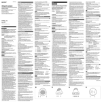
3-868-624-11 (2) ATTENTION The electromagnetic fields at specific frequencies may influence the picture of the unit. Network Camera Installation Manual Before operating the unit, please read this manual thoroughly and retain it for future reference. Manuel d’installation Avant d’utiliser cet appareil, lisez attentivement le présent mode d’emploi et conservez-le pour toute référence ultérieure. • The Network Camera system and related service is not a security service. When monitoring the image and audio of the purchased Network Camera, there is a risk that the monitoring image or audio may be viewed or used by a thirdparty via the network. It is provided only as a convenience for people to easily access their cameras via the internet. When you use the Network Camera, please take into account and ensure the privacy and portrait right of the object at your own responsibility. • Access to the camera or system is limited to the user setting up a user name and password only. No further authentication is provided nor should the user presume that such filtering is done by the service. • Sony assumes no liability should the service related to the Network Camera goes down or interrupted for whatever reason. Features SNC-P5 2005 Sony Corporation Printed in Japan The SNC-P5 is a network camera equipped with a built-in Web server. The camera has the following features: • Real-time monitoring of the image and sound from the camera is possible using the Web browser on the computer. • MPEG4 video compression allows a smooth streaming of motion pictures with 30 fps (QVGA size). Motion JPEG video streaming is also possible by selecting the JPEG video compression format. • The 1/4 type CCD* supporting VGA offers high-quality video streaming in VGA size. (The frame rate in VGA size is less than 30 fps.) * CCD: Charge-Coupled Device English Owner’s Record The model and serial numbers are located on the bottom. Record the serial number in the space provided below. Refer to these numbers whenever you call upon your Sony dealer regarding this product. Model No. SNC-P5 Serial No. WARNING To prevent fire or shock hazard, do not expose the unit to rain or moisture. To avoid electrical shock, do not open the cabinet. Refer servicing to qualified personnel only. AC power adaptor Model No.: MPA-AC1 (Sony) CAUTION: This unit is for use only with the supplied AC power adaptor. Use with other AC power adaptors may cause hazards such as a fire. WARNING This installation should be made by a qualified service person and should conform to all local codes. • It adopts 3× optical zoom lens and is equipped with Pan/Tilt functions. They can be operated by remote control from Web browser. • A microphone (monaural) is built in the camera. Also, the built-in microphone jack (minijack, monaural) accepts a commercially available plug-in-power microphone (rated voltage: 2.5V DC). • The line output jack (minijack, monaural) allows connection of a commercially available speaker system with the built-in amplifier so that the sound transmitted via the network can be output from the connected speaker system. • It is equipped with the motion detection function (in MPEG4 mode), sensor input terminals (two lines) and an alarm output terminal. You can send images from the camera as an E-mail attachment or to an FTP server by synchronizing with motion detection or external sensor input. or control peripheral devices connected to the alarm output terminal. • Inserting the wireless CF card SNCA-CFW1 (option) especially designed to use with this camera into the CF card slot enables transmission of images from the camera via wireless LAN. • The camera is supplied with the IP Setup Program for easy performance of the network setting. Notes on Use Operating or storage location CAUTION Avoid operating or storing the camera in the following locations: • Extremely hot or cold places (Operating temperature: 0 °C to +35 °C [32 °F to 95 °F]) • Exposed to direct sunlight for a long time, or close to heating equipment (e.g., near heaters) • Close to sources of strong magnetism • Close to sources of powerful electromagnetic radiation, such as radios or TV transmitters • Locations subject to strong vibration or shock The rating label is located on the bottom. Ventilation CAUTION for LAN port To prevent heat buildup, do not block air circulation around the camera. WARNING A readily accessible disconnect device shall be incorporated in the building installtion wiring. WARNING (for Installers only) Instructions for installing the equipment on the ceiling or the wall: After the installtion, ensure the connection is capable of supporting at least a force of 50 Newtons (N) downwards. For safety reason, do not connect the LAN port to any network devices that might have excessive voltage. For the customers in the U.S.A. Treatment of the lens cover This equipment has been tested and found to comply with the limits for a Class B digital device, pursuant to Part 15 of the FCC Rules. These limits are designed to provide reasonable protection against harmful interference in a residential installation. This equipment generates, uses, and can radiate radio frequency energy and, if not installed and used in accordance with the instructions, may cause harmful interference to radio communications. However, there is no guarantee that interference will not occur in a particular installation. If this equipment does cause harmful interference to radio or television reception, which can be determined by turning the equipment off and on, the user is encouraged to try to correct the interference by one or more of the following measures: Take care not to stain, rap on or press strongly the lens cover which covers the lens of the camera. These acts may inhibit the camera to bring out its performance enough and may cause a malfunction. – Reorient or relocate the receiving antenna. – Increase the separation between the equipment and receiver. – Connect the equipment into an outlet on a circuit different from that to which the receiver is connected. – Consult the dealer or an experienced radio/TV technician for help. If you have any questions about this product, you may call: Sony's Business Information Center (BIC) at 1-800-686-SONY (7669) or Write to: Sony Customer Information Services Center 6900-29, Daniels Parkway, PMB 330 Fort Myers, Florida 33912 Declaration of Conformity Trade Name : SONY Model No : SNC-P5 Responsible Party: Sony Electronics Inc. Address : 16450 W. Bernardo Dr, San Diego, CA 92127 U.S.A. Telephone Number : 858-942-2230 This device complies with part 15 of the FCC rules. Operation is subject to the following two conditions: (1) This device may not cause harmful interference, and (2) this device must accept any interference received, including interference that may cause undesired operation. Transportation When transporting the camera, repack it as originally packed at the factory or in materials of equal quality. Cleaning • Use a blower to remove dust from the lens cover. • Use a soft, dry cloth to clean the external surfaces of the camera. Stubborn stains can be removed using a soft cloth dampened with a small quantity of detergent solution, then wipe dry. • Do not use volatile solvents such as alcohol, benzene or thinners as they may damage the surface finishes. Note on laser beams Laser beams may damage a CCD. You are cautioned that the surface of a CCD should not be exposed to laser beam radiation in an environment where a laser beam device is used. CCD Characteristics The following conditions may be observed when using a CCD camera. They are not due to any fault within the camera. Vertical smear: This phenomenon occurs when viewing a very bright object. Jagged picture: When viewing stripes, straight lines, or similar patterns, the image on the screen may appear jagged. About the Supplied Manuals The following manuals are supplied with this unit. Installation Manual (this document) You are cautioned that any changes or modifications not expressly approved in this manual could void your authority to operate this equipment. The Installation Manual describes the names and functions of the parts of the camera, the installation and connections of the camera, etc. Be sure to read it before operating the camera. The shielded interface cable recommended in this manual must be used with this equipment in order to comply with the limits for a digital device pursuant to Subpart B of Part 15 of FCC Rules. User’s Guide (stored in the CD-ROM) For customers in Canada This Class B digital apparatus complies with Canadian ICES-003. Cet appareil numérique de la classe B est conforme à la norme NMB-003 du Canada. The User’s Guide describes the setup of the camera and the operations from the Web browser. To open the User’s Guide, see “Using the CD-ROM Manuals” below. NOTICE TO USERS © 2005 Sony Corporation. All rights reserved. This manual or the software described herein, in whole or in part, may not be reproduced, translated or reduced to any machine readable form without prior written approval from Sony Corporation. SONY CORPORATION PROVIDES NO WARRANTY WITH REGARD TO THIS MANUAL, THE SOFTWARE OR OTHER INFORMATION CONTAINED HEREIN AND HEREBY EXPRESSLY DISCLAIMS ANY IMPLIED WARRANTIES OF MERCHANTABILITY OR FITNESS FOR ANY PARTICULAR PURPOSE WITH REGARD TO THIS MANUAL, THE SOFTWARE OR SUCH OTHER INFORMATION. IN NO EVENT SHALL SONY CORPORATION BE LIABLE FOR ANY INCIDENTAL, CONSEQUENTIAL OR SPECIAL DAMAGES, WHETHER BASED ON TORT, CONTRACT, OR OTHERWISE, ARISING OUT OF OR IN CONNECTION WITH THIS MANUAL, THE SOFTWARE OR OTHER INFORMATION CONTAINED HEREIN OR THE USE THEREOF. Sony Corporation reserves the right to make any modification to this manual or the information contained herein at any time without notice. The software described herein may also be governed by the terms of a separate user license agreement. Using the CD-ROM Manuals Français The supplied CD-ROM disc includes the User’s Guides for this unit (Japanese, English, French, German, Spanish, Italian and Chinese versions). CD-ROM System Requirements The following are required to access the supplied CD-ROM disc. • Computer: PC with Intel Pentium CPU Installed memory: 64 MB or more CD-ROM drive: × 8 or faster • Monitor: Monitor supporting resolution of 800 × 600 or higher • OS: Microsoft Windows Millennium Edition, Windows 2000 Service Pack 2, Windows XP Professional or Home Edition When these requirements are not met, access to the CD-ROM disc may be slow, or not possible at all. Preparations The Adobe Acrobat Reader Version 4.0 or later or the Adobe Reader Version 6.0 or later must be installed on your computer in order to use the User’s Guide contained in the CD-ROM disc. If Adobe Acrobat Reader or Adobe Reader is not installed, it may be downloaded from the following URL: http://www.adobe.com/products/acrobat/readstep2.html Reading the manual in the CD-ROM To read the User’s Guide contained in the CD-ROM disc, do the following. 1 Insert the supplied CD-ROM disc into your CD-ROM drive. After a short time a window will open displaying the files on the CD-ROM. 2 Click the PDF file named the language you wanto to read. Application will start, then display the cover page of the User’s Guide. Clicking an item in the Table of Contents allows you to jump to the relevant page. Note If you lose the CD-ROM disc or become unable to read its content, for example, because of a hardware failure or improper use of the disc, contact a Sony service representative for replacement (not free). Location and Function of Part AVERTISSEMENT Afin d’éviter tout risque d’incendie ou d’electrocution, ne pas exposer cet appareil à la pluie ou à l’humidité. Afin d’écarter tout risque d’électrocution, garder le coffret fermé. Ne confier l’entretien de l’appareil qu’à un personnel qualifié. Adaptateur secteur N° de modèle : MPA-AC1 (Sony) ATTENTION : Cet appareil ne doit être utilisé qu’avec l’adaptateur secteur fourni. L’utilisation avec un autre adaptateur secteur fait courir un risque d’incendie ou autre. Traitement du cache d’objectif Veillez à ne pas tacher, heurter ou exercer une forte pression sur le cache d’objectif qui protège l’objectif de la caméra. Ceci pourrait affecter le bon fonctionnement de la caméra et provoquer un dysfonctionnement. AVERTISSEMENT L’installation doit être effectuée par un technicien qualifié et se conformer à toute la réglementation locale. AVERTISSEMENT Un dispositif coupe-circuit facilement accessible doit être incorporé au câblage de l’installation du bâtiment. AVERTISSEMENT (pour les installateurs seulement) Instructions pour l’installation du matériel au plafond : Après l’installation, assurez-vous que le montage est suffisamment solide pour supporter au moins une force de 50 Newtons (N) vers le bas. 1 NETWORK indicator Flashes in green when the camera is connected to the network. Goes off when the camera is not connected to the network. 2 Built-in microphone Évitez d’utiliser ou de ranger la caméra dans les endroits suivants : • endroits très chauds ou froids (température de fonctionnement : 0 °C à + 35 °C [32 °F à 95 °F]) • endroits longuement exposés aux rayons directs du soleil ou à proximité d’un appareil de chauffage (radiateurs, par exemple) • proximité de sources magnétiques puissantes • proximité d’un rayonnement électromagnétique puissant (émetteurs de radio ou de télévision, par exemple) • Emplacements soumis à de fortes vibrations ou chocs Pour la sécurité, ne connectez pas le port réseau local à un périphérique réseau susceptible de présenter une tension excessive. B Take off the cap on the right side of the camera, and you can see the CF cars slot. 4 CF card eject switch Press it when it is not easy to remove the CF card from the slot. 5 Reset switch To reset the camera to the factory default settings, hold down this switch and supply the power to the camera. 6 Compact Flash (CF) card slot Insert the wireless LAN card “SNCA-CFW1” especially designed to use with this camera or the storage (not supplied) into the slot. And the SNCA-CFW1 can be attached with the optional antenna SNCA-AN1. It can expand the transmission area with the wireless LAN. C Top Take off the cap on the top of the camera, and you can see the connectors. Sensor input 1 – Sensor input 1 + Sensor input 2 – Sensor input 2 + Cet appareil numérique de la classe B est conforme à la norme NMB003 du Canada. Description AC/DC 24 V max., 1 A Mechanical relay output, electrically isolated from the camera Make contact Make contact 8 m (microphone input) jack (minijack, monaural) Connect a commercially available microphone. This jack supports plug-in-power microphones (rated voltage: 2.5V DC). Note When an external microphone is connected to the m jack, it has priority over the built-in microphone, and the built-in microphone can not be used. 9 5 (line output) jack (minijack, monaural) Connect a commercially available speaker system with the built-in microphone. q; T (video output) jack (minijack) Output a composite video signal. qa DC IN 12 V (power input) connector Connect the supplied AC power adaptor. (network) port (RJ-45) qs Connect to a hub on the 10BASE-T/100BASE-TX network using a network cable (UTP, category 5). qd Hole for the drop-prevention strap Feed the drop-prevention strap through this hole. qf Tripod screw Attach the supplied stand to this screw. When attaching the camera to a tripod or stand other than the supplied stand, use the following mounting screw. Pour prévenir toute surchauffe interne, n’entravez pas la circulation d’air autour de la caméra. Traitement du cache d’objectif • Le système de caméra en réseau et le service qui lui est lié ne sont pas sécurisés. Lorsque vous surveillez l’image et le son de la caméra en réseau dont vous avez fait l’acquisition, il existe un risque que l’image de contrôl puisse être visualisée ou que le son puis être utilisé par un tiers via le réseau. Ce service n’est fourni aux utilisateurs que comme moyen pratique d’accéder à leurs caméras via l’Internet. Lorsque vous utilisez la caméra en réseau, veuillez prendre en compte ce fait pour assurer la confidentialité et visualisez l’objet à vos risques et périls. Veillez, en outre, à respecter le droit d’image des personnes et des biens filmés. • L’accès à la caméra ou au système est limitée à l’utilisateur qui configure un nom d’utilisateur et un mot de passe. Aucune autre mesure d’authentification n’est fournie et l’utilisateur ne doit pas croire que le service exécute un autre filtrage quelconque. • Sony décline toute responsabilité en cas de panne ou d’interruption du service de caméra en réseau due à quelque cause que ce soit. © 2005 Sony Corporation. Tous droits réservés. Ce manuel ou le logiciel qui y est décrit ne doit pas être, même partiellement, reproduit, traduit ou réduit sous une forme lisible par les ordinateurs sans l’autorisation écrite préalable de Sony Corporation. SONY CORPORATION NE DONNE AUCUNE GARANTIE POUR CE MANUEL, LE LOGICIEL OU TOUTE INFORMATION QU’ILS CONTIENNENT ET DÉCLINE EXPRESSÉMENT PAR LES PRÉSENTES TOUTE GARANTIE TACITE DE QUALITÉ MARCHANDE OU D’APTITUDE À UN USAGE PARTICULIER POUR CE MANUEL, LE LOGICIEL OU TOUTE INFORMATION QU’ILS CONTIENNENT. EN AUCUN CAS, SONY CORPORATION NE POURRA ÊTRE TENU RESPONSABLE DE DOMMAGES ACCESSOIRES, INDIRECTS OU PARTICULIERS QU’ILS SOIENT BASÉS SUR LA RESPONSABILITÉ CIVILE, LE CONTRAT OU AUTRE, DUS OU AFFÉRENTS À CE MANUEL, AU LOGICIEL OU À TOUTE AUTRE INFORMATION QU’ILS CONTIENNENT OU À LEUR UTILISATION. Sony Corporation se réserve le droit de modifier ce manuel ou les informations qu’il contient à tout moment sans préavis. Le logiciel décrit dans ce manuel peut également être régi par les clauses d’un contrat de licence utilisateur séparé. sont des marques de commerce de • “IPELA” et Sony Corporation. • Microsoft, Windows, Internet Explorer et MS-DOS sont des marques déposées de Microsoft Corporation aux États-Unis et/ ou dans d’autres pays. • Java est une marque de Sun Microsystems, Inc. aux ÉtatsUnis et dans d’autres pays. • Intel et Pentium sont des marques déposées d’Intel Corporation ou de ses filiales aux États-Unis et dans d’autres pays. • Adobe, Acrobat et Adobe Reader sont des marques d’ Adobe Systems Incorporated aux États-Unis et/ou dans d’autres pays. D Rear Aération Veillez à ne pas tacher, heurter ou exercer une forte pression sur le cache d’objectif qui protège l’objectif de la caméra. Ceci pourrait affecter le bon fonctionnement de la caméra et provoquer un dysfonctionnement. Tous les autres noms de société et de produit sont des marques ou des marques déposées des sociétés respectives ou de leurs fabricants respectifs. Caractéristiques U1/4”, 20 UNC = 4.5 mm ± 0.2 mm (ISO standard) Note La SNC-P5 est une caméra réseau équipée d’un serveur Internet intégré. Elle offre les fonctionnalités suivantes : • Il est possible de contrôler l’image et le son de la caméra en temps réel en utilisant le navigateur Internet de l’ordinateur. Use the mounting screw whose length is 4.5 mm ± 0.2 mm only. Use of other screws may cause improper mounting and damage parts inside the camera. All other company and product names are trademarks orregistered trademarks of the respective companies ortheir respective makers. Remarque Si vous égarez le CD-ROM ou ne parvenez pas à en lire le contenu (en raison d’une défaillance du matériel ou d’une mauvaise utilisation du disque, par exemple), adressez-vous au service après-vente Sony pour son remplacement (ceci n’est pas gratuit). Emplacement et fonction des pièces A Avant 1 Témoin NETWORK Clignote en vert lorsque la caméra est connectée à un réseau. S’éteint lorsque la caméra n’est pas connectée à un réseau. B Droite Retirez le chapeau du côté droit de la caméra pour accéder à la fente carte CF. 4 Interrupteur d’éjection de carte CF Appuyez dessus lorsqu’il est difficile de retirer la carte CF de la fente. 5 Interrupteur de RESET (réinitialisation) Pour réinitialiser la caméra aux réglages d’usine, maintenez cet interrupteur enfoncé lors de la mise sous tension de la caméra. 6 Fente carte CF Insérez la carte réseau local sans fil «SNCA-CFW1» spécialement destinée à cette caméra ou au stockage (non fourni) dans la fente. Et la carte SNCA-CFW1 peut être montée avec l’antenne en option SNCA-AN1. Elle peut étendre la zone de transmission avec le réseau local sans fil. C Faces supérieure Transportez la caméra dans son emballage d’origine ou dans un emballage d’égale qualité. Retirez le chapeau supérieur de la caméra pour accéder aux connecteurs. Nettoyage 7 Port d’E/S (Entrée/Sortie) Ce port est utilisé comme bornes d’entrée de capteur et de sortie d’alarme. Raccordez-le aux périphériques. Pour plus d’informations sur l’utilisation voir « Utilisation du port d’E/S ». • Utilisez un pinceau soufflant pour enlever la poussière du cache d’objectif. • Utilisez un chiffon doux et sec pour nettoyer l’extérieur de la caméra. Vous pouvez faire partir les taches persistantes en frottant avec un chiffon doux imbibé d’une petite quantité de solution détergente, puis en essuyant. • N’utilisez pas de solvants volatils tels qu’alcool, benzène ou diluants. Ils pourraient endommager la finition. Remarque concernant les faisceaux laser Les faisceaux laser peuvent endommager un capteur CCD. N’exposez pas la surface d’un capteur CCD au rayonnement laser dans un environnement où un appareil à faisceau laser est utilisé. Caractéristiques du CCD Il se peut que vous constatiez les conditions suivantes lors de l’utilisation d’une caméra CCD. Ces conditions ne sont pas dues à une anomalie de la caméra. Maculage vertical : Ce phénomène se produit lors de la visualisation d’objets très lumineux. Image « en escalier » : Lorsque vous visualisez des rayures, des lignes droites ou des motifs similaires, il se peut que l’image à l’écran apparaisse « en escalier ». N° de broche 1 2 3 4 5 6 Signal Sortie d’alarme – Sortie d’alarme + Description 24 V CA/CC max., 1 A Sortie de relais mécanique électriquement isolée de la caméra Entrée de capteur 1 – Contact à fermeture Entrée de capteur 1 + Entrée de capteur 2 – Contact à fermeture Entrée de capteur 2 + 8 Prise m (entrée de micro) (mini-jack, mono) Permet de raccorder un micro en vente dans le commerce. Cette prise prend en charge des micros auto-alimentés (tension nominale : 2,5 V CC). Remarque Si vous raccordez un micro externe à la prise m, ce micro a priorité sur le micro intégré qui est alors coupé. 9 Prise 5 (sortie de ligne) (mini-jack, mono) Permet de raccorder des enceintes en vente dans le commerce avec micro intégré. q; Prise T (sortie vidéo) (mini-jack) Émet un signal vidéo composite. Notes sur les manuels fournis qa Connecteur DC IN 12 V (entrée d’alimentation) Permet de brancher l’adaptateur secteur fourni. Les manuels suivants sont fournis avec cet appareil. Manuel d’installation (ce manuel) Le Manuel d’installation décrit la nomenclature et les fonctions des pièces, l’installation et les raccordements de la caméra, etc. Lisezle impérativement avant l’utilisation. Guide de l’utilisateur (sur le CD-ROM) Le Guide de l’utilisateur décrit l’installation de la caméra et les opérations depuis le navigateur Internet. Pour ouvrir le Guide de l’utilisateur, voir « Utilisation des manuels sur le CD-ROM » ci-dessous. Utilisation des manuels sur le CD-ROM Le CD-ROM fourni contient les Guides de l’utilisateur pour cet appareil (versions japonaise, anglaise, franÿaise, allemande, espagnole, italienne et chinoise). Configuration système requise de CD-ROM (réseau) (RJ-45) qs Port Raccordez ce port à un concentrateur (hub) sur un réseau 10BASE-T/100BASE-TX à l’aide d’un câble réseau (UTP, catégorie 5). qd Orifice pour la sangle anti-chute Faites passer la sangle anti-chute par cet orifice. D Arrière qf Filetage pour trépied Montez le socle fourni sur ce filetage. Si vous montez la caméra sur un trépied ou socle autre que le socle fourni, utiliser la vis de montage suivante. U1/4”, 20 UNC = 4,5 mm ± 0,2 mm (norme ISO) Remarque La configuration suivante est requise pour l’accès au CD-ROM fourni : • Ordinateur : Ordinateur avec processeur Intel Pentium Mémoire installée : 64 Mo ou plus Lecteur CD-ROM : × 8 ou plus rapide • Écran : Écran avec une résolution de 800 × 600 ou plus • Système d’exploitation : Microsoft Windows Millennium Edition, Windows 2000 Service Pack 2, Windows XP Professionnel ou Édition familiale Utilisez une vis de montage avec une longueur de 4,5 mm ± 0,2 mm seulement. L’utilisation d’autre vis pourrait entraîner un montage incorrect et endommager des pièces à l’intérieur de la caméra. qg Fente de fixation pour support de montage mural Si ces conditions ne sont pas satisfaites, l’accès au CD-ROM peut être lent ou impossible. Préparation Pour pouvoir ouvrir le Guide de l’utilisateur se trouvant sur le CDROM, le logiciel Adobe Acrobat Reader version 4.0 ou plus récente ou Adobe Reader Version 6.0 ou plus récente doit être installé sur l’ordinateur. Contrôle de l’image de la caméra Installez et raccordez correctement la caméra en suivant les instructions de ce manuel, puis utilisez la caméra comme il est indiqué dans le Guide de l’Utilisateur se trouvant sur le CDROM fourni. (suite au verso) qg Attachment slit for wall-mounting bracket A B C D Monitoring the Camera Image Install and connect the camera properly following the instructions in this manual, then operate the camera referring to the User’s Guide contained in the supplied CD-ROM. (continued on the reverse side) • “IPELA” and are trademarks of Sony Corporation. • Microsoft, Windows, Internet Explorer and MS-DOS are registered trademarks of Microsoft Corporation in the United States and/or other countries. • Java is a trademark of Sun Microsystems, Inc. in the United States and other countries. • Intel and Pentium are registered trademarks of Intel Corporation or its subsidiaries in the United States andother countries. • Adobe, Acrobat and Adobe Reader are trademarks of Adobe Systems Incorporated in the United States and/or other countries. Pour lire le Guide de l’utilisateur se trouvant sur le CD-ROM, procédez comme suit : 1 Insérez le CD-ROM fourni dans le lecteur CD-ROM. Après un court instant, une fenêtre affichant les fichiers du CD-ROM s’ouvre. 2 Cliquez sur le fichier PDF de la langue que vous désirez lire. L’application est lancée, puis la page de couverture du guide de l’utilisateur s’affiche. En cliquant sur une entrée de la table des matières, vous pouvez accéder à la page correspondante. Transport AVIS AUX UTILISATEURS 7 I/O (Input/Output) port This port is used as a sensor input and alarm output terminals. Connect it to peripheral devices. For details on use, see “Using the I/O port.” 3 4 5 6 Pour les utilisateurs au Canada Des champs électromagnétiques à des fréquences spécifiques peuvent avoir un effet sur la qualité de l’image de l’appareil. Right side Pin No. Signal 1 Alarm output – 2 Alarm output + Eviter d’exposer l’appareil à des gouttelettes ou à des éclaboussures et ne placer aucun objet rempli de liquide, comme un vase, sur l’appareil. Lecture du manuel sur CD-ROM 3 Témoin POWER (alimentation) S’allume à la mise sous tension. Lieu d’utilisation ou de rangement PRECAUTION pour le port réseau local Si le logiciel Adobe Acrobat Reader ou Adobe Reader n’est pas installé sur l’ordinateur, vous pouvez le télécharger à l’adresse suivante : http://www.adobe.com/products/acrobat/readstep2.html 2 Micro intégré Remarques sur l’utilisation La plaquette des caractéristiques nominales se trouve sur la face inférieure. PRECAUTION 3 Power indicator Lights up when the power is turned on. * CCD: Dispositif à couplage de charge • La caméra comporte un objectif à zoom optique 3× et des fonctions de panoramique/inclinaison. Les fonctions peuvent être commandées à distance depuis un navigateur Internet. • Un micro (mono) est intégré à la caméra. La prise du micro intégré (mini-jack, mono) accepte un micro auto-alimenté en vente dans le commerce (tension nominale : 2,5 V CC). • La prise de sortie de ligne (mini-jack, mono) permet le branchement d’enceintes amplifiées disponibles dans le commerce de faÿon que le son transmis sur le réseau puisse être émis par elles. • La caméra est dotée d’une fonction de détection de mouvement (en mode MPEG4), de bornes d’entrée de capteur (deux lignes) et d’une borne de sortie d’alarme. Les images de la caméra peuvent être envoyées par e-mail ou à un serveur FTP à la détection d’un mouvement ou la réception d’un signal de capteur externe, et des périphériques connectés à la borne de sortie d’alarme peuvent être commandés. • Si la carte sans fil CF SNCA-CFW1 (en option) specialement destinee a cette camera est inseree dans la fente carte CF, des images peuvent etre envoyees depuis la camera sur un reseau local sans fil. • La caméra est livrée avec un programme d’installation IP qui facilite l’exécution de la configuration du réseau. PRECAUTION ATTENTION A Front • La compression vidéo MPEG4 assure une transmission en continu régulière d’images animées avec un taux de trame de 30 images/seconde (format QVGA). La transmission vidéo JPEG en continu d’images animées est également possible en sélectionnant le format de compression vidéo JPEG. • Le CCD* type 1/4 prenant en charge le format VGA offre une transmission vidéo en continu de haute qualité en format VGA. (Le taux de trame du format VGA est inférieur à 30 images/ seconde.) DC IN 12V I/O m 4 5 1 2 3 6 5 ! 7 8 9 0 qa qs qd qf qg E H Specifications Installation 1 Network Notes • When you attach the camera to a wall or ceiling, entrust the installation to an experienced contractor or installer. • Attach the camera to the wall or ceiling firmly after making sure the wall or ceiling is strong enough to bear the weight of the camera and the stand. If it is not strong enough, the camera may fall and cause serious injury. • Be sure to fix the supplied strap to a junction box, wall or ceiling with a screw to prevent the camera from falling. • Check periodically, at least once a year, to ensure that the connection has not loosened. If conditions warrant, make this periodic check more frequently. • According to the installing position, illumination may be got into an image. In this case, change the installing position. Tapping screw Vis tarauduses 3-1 Installing on a wall E To install the camera on a wall, use the supplied wall-mounting bracket. 1 Fix the wall-mounting bracket to the wall with the supplied 2 tapping screws. 2 Connect the AC power adaptor and the LAN cable to the 3 3-2 camera. See “Connecting Power and Network” for details of connection. Install the camera on the wall. 1 Attach the camera as an illustration to the wall-mounting bracket fixed on the wall. 2 Push the camera downward. Notes • When you install the camera on a wall using the wall mounting bracket, take care not to trap the AC power cord or the LAN cable between the camera and the wall. • Secure the screws firmly so that they will not come loose. I Installing on a Ceiling When installing the camera on a ceiling, use the supplied stand. Note Install it on an even place of the ceiling. If it is installed on a tilted place, a tilting image is displayed during PanTilt action. Mounting diagram F F Use this diagram when you determine the positions and sizes of the wiring hole and the mounting holes for the supplied stand. 6.5 (9/32) 47 (1 7/8) 16 (21/32) Mounting screws Wiring hole Orifice de câblage The supplied stand is provided with three mounting holes. Install the stand to a ceiling or wall with screws through these holes. The required mounting screws differ depending on the installation location and its material. J Steel wall or ceiling: Use M4 bolts (not supplied) and nuts. Wood wall or ceiling: Use the supplied tapping screws (4 × 20). The panel thickness must be 15 mm (5/8 inch) or more. Concrete wall: Use appropriate anchors, bolts and plugs (not supplied) for concrete walls. Junction box: Use screws (not supplied) to match the holes on the junction box. 4. ø8 1 3-20˚ DC IN 12V 83.5 (3 3/8) 5 I/O /) 3 8 (8 m 5 ! Installing the supplied stand G 1 Attach the supplied stand to the ceiling with a screw as the DC IN 12V Stand mounting holes / Orifices de montage du socle 3 2 4 Unit: mm (inches) / Unité: mm (pouces) 5 3 G 2 1 10BASE-T/100BASE-TX 4 Before installing the stand to the ceiling, feed the wires extended from the ceiling or wall through the opening on the rear of the stand. 7 Installing on a Shelf or a Desk Top H When installing the camera on a wall, use the supplied stand. Note When you install the camera on a tall shelf, an injury or breakage may result if only the rubber feet are attached to the rear of the stand. The camera and the stand must be fixed to the shelf or desktop with screws or similar. K 1 2 3 4 5 6 1 2 3 4 5 6 I/O I/O Drop-prevention strap I When installing the camera, be sure to use the supplied dropprevention strap. First, feed the string through the hole on the rear of the camera. Fix it with a screw (not supplied) to the junction box or something of the wall or ceiling. 1 3-2 Concavity part / Partie concave 2 1 Connecting Power and Network 2 3.3V Convexity part / Partie convexe Note 5V 2.35 k When you connect the network cable, cables for the microphone input connector and for the line output connectors, the cap of the connectors section may not close. In this case, leave it open during use because forcing the cap close may be a cause of a trouble. 3 4 6 Ethernet connection 6 3 4 Tighten firmly. Serrer à fond. J 5 5 Connect the network port of this unit to the router or the hub with a commercially available network cable (straight), and connect the AC adapter to the DC IN 12V connector. 1 SNC-P5 (top) 2 Commercially available network cable (straight cable) 3 Sony MPA-AC1 AC power adaptor (supplied) Use the supplied plug adapter to match to the configuration of the outlet. 4 Power cord (supplied) 5 To a wall outlet 6 Router or Hub 7 Network 7 L SNC-P5 110 (4 3/8) 4 DC IN 12V I/O m 5 Using the I/O Port Connecting the wire While holding down the button on the slot to which you want to connect the wire (AWG No. 28 to 22) with a small slotted screwdriver, insert the wire into the slot. Then release the screwdriver from the button. Repeat this procedure to connect all required wires. ! ø130 (5 1/8) Stand/Socle Wiring diagram for sensor input 106 (41/4) 178 (7 1/8) 113 (4 1/2) Mechanical switch/open corrector output device 130 (51/8) K 142 (55/8) Unit: mm (inches) / Unité: mm (pouces) 1 2 3 4 5 6 Camera inside Outside Pin 4 (Sensor input +) Pin 3 (Sensor input –) Ground Mechanical switch or open collector output device 1 2 3 4 5 6 7 Camera inside Outside Pin 2 (Alarm output +) Magnet relay 24 V AC/24 V DC, 1A or less Pin 1 (Alarm output –) Circuit example Ground Wiring diagram for alarm output TCP/IP, ARP, ICMP, HTTP, FTP (server/ client), SMTP (client), DHCP (client), DNS (client), NTP (client), SNMP (MIB-2), RTP/RTCP, PPPoE Video compression format MPEG4/JPEG (selectable) Audio compression format G.711, G.726 (40, 32, 24, 16 kbps) Image size 640 × 480 (VGA), 480 × 360, 384 × 288, 320 × 240 (QVGA), 256 × 192, 160 × 120 (QQVGA) Maximum frame rate Max. 30 FPS (QVGA) Web browser Internet Explorer Ver. 5.5 or 6.0 (Available OS: Windows 2000/ XP) Computer environments CPU: Pentium III, 1 GHz or higher (Pentium 4, 2 GHz or higher recommended) RAM: 256 MB or more Display size: 1024 × 768 Maximum user access In JPEG mode: 20 users In MPEG4 mode: 10 users Network security Password (basic authentication), IP filtering Homepage customization Starting from a homepage in the built-in flash memory or CF is possible. Other functions Motion detection, Cropping, Built-in clock, etc. • Pour un montage de la caméra au mur ou au plafond, confiez l’installation à un prestataire ou installateur expérimenté. • Montez solidement la caméra au mur ou au plafond après vous être assuré que celui-ci est suffisamment robuste pour supporter le poids de la caméra et du socle. La caméra risquerait autrement de tomber et de provoquer de graves blessures. • Fixez impérativement la sangle fournie à une boîte de jonction, etc. pour empêcher la caméra de tomber. • Assurez-vous périodiquement (au moins une fois par an) que l’accouplement n’est pas desserré. Si les conditions le permettent, effectuez cette vérification périodique plus fréquemment. • Selon la position d’installation, il se peut que l’éclairage apparaisse sur l’image. Changez alors la position d’installation. Installation au mur Pour installer la caméra au mur, utilisez le support de montage mural fourni. 1 2 3 Image device 1/4 inch color CCD Effective picture elements Approx. 330,000 Built-in lens 3× (Zoom ratio) Focal length: f=3.4 to 10.2 mm Maximum F number: F (WIDE marge) 2.8 to F (TELE marge) 3.9 View angle: 20° - 55.8° (horizontal), 15.1° - 43.3° (vertical) Shooting distance: WIDE marge 0.4 m, TELE marge 1.4 m Minimum illumination 3.5 lx (AGC ON, F2.8, 30IRE) Horizontal resolution 400 TV (WIDE marge) Video S/N -48 dB Shutter speed 1 to 1/10,000 s Mechanism Pan action Tilt action -60 ° to + 60 ° Maximum speed: 90 ° / s -65 ° to +10 ° Maximum speed: 90 ° / s Interface Network port I/O port 10BASE-T/100BASE-TX (RJ-45) Sensor input : × 2, make contact Alarm output : × 1, 24 V AC/DC max, 1 A (mechanical relay outputs electrically isolated from the camera) Mini jack (1.0 Vp-p, 75 ohms, unbalanced, sync negative) * Use an AV cable with AV 3-prong mini plug or AV 4-prong mini plug. A video cable with a monaural mini plug cannot be used. CF card slot Built-in microphone Mic input Line output Supporting Type I/Type II Electret condenser microphone (omnidirectional) Minijack (monaural) Plug-in-power supported (rated voltage: 2.5 V DC) Recommended load impedance 2.2 kohms Minijack (monaural), Maximum output level: 1 Vrms Others Power supply Power consumption Operating temperature Operating humidity Storage temperature Storage humidity Mass Dimensions (L) 12 V DC 6.2 W 0 °C to +35 °C (32 °F to 95 °F) 20 to 80 % -20 °C to +60 °C (-4 °F to +140 °F) 20 to 95 % Camera: Approx. 380 g (13.4 oz) Stand: Approx. 360 g (12.7 oz) Camera: 130 × 130 × 110 mm (w/h/d) (5 1/8 × 5 1/8 × 4 3/8 inches) not including the projecting parts Stand: 130 × 178 × 142 mm (w/h/d) (5 1/8 × 7 1/8 × 5 5/8 inches) Supplied accessories AC power adaptor MPA-AC1 (Sony) (1), Power cord (1), Stand (1), Wall-mounting bracket (1), Rubber foot (4), Drop-prevention strap (1), Tapping screw (3), CD-ROM (User’s Guide and supplied programs) (1), Installation manual (1) Optional accessories Wireless card SNCA-CFW1 Wireless LAN antenna SNCA-AN1 Memory stick Duo adapter corresponding to Compact MSAC-MCF1 FlashTM slot Memory stick Duo MSX-M512S (512MB) Design and specifications are subject to change without notice. Regular parts replacement Some of the parts that make up this product (electrolytic condenser, for example) need replacing regularly depending on their life expectancies. The lives of parts differ according to the environment or condition in which this product is used and the length of time it is used, so we recommend regular checks. Consult the dealer from whom you bought it for details. Spécifications Réseau Protocole Fixez le support de montage mural au mur avec les 4 vis taraudeuses fournies. Raccordez l’adaptateur secteur et le câble réseau local à la caméra. Pour plus d’informations sur ce raccordement, voir « Raccordement à l’alimentation et au réseau ». Installez la caméra au mur. 1 Montez la caméra sur le support de montage mural fixé au mur comme sur l’illustration. 2 Poussez la caméra vers le bas. Remarques Installation au plafond Lors de l’installation de la caméra au plafond, utilisez le socle fourni. Remarque Installez la camera sur une partie horizontale du plafond. Si vous l’installiez sur une partie inclinee, l’image apparaitrait inclinee lors des operations PanTilt. Schéma de montage F Utilisez ce schéma pour déterminer la position et la taille de l’orifice de câblage et des orifices de montage du socle fourni. Vis de montage Le socle fourni comporte trois orifices de montage. Posez le socle au plafond ou au mur en faisant passer des vis par ces orifices. Les vis de montage requises diffèrent selon l’emplacement et le matériau de la surface d’installation. Mur ou plafond en acier : Utilisez des boulons M4 (non fournis) et des écrous. Mur ou plafond en bois : Utilisez les vis taraudeuses (4 × 20) fournies. L’épaisseur de panneau doit être d’au moins 15 mm (5/8 pouce). Mur en béton : Utilisez des ancrages, boulons et chevilles (non fournis) pour mur en béton appropriés. Boîte de jonction : Utilisez des vis (non fournies) adaptées aux orifices de la boîte de jonction. Installation du socle fourni G 1 Montez le socle fourni au plafond avec une vis comme sur l’illustration. 2 Faire passer l’adaptateur secteur ou le câble réseau à travers le socle fixé et le raccorder à la caméra. Format de compression vidéo MPEG4/JPEG (sélectionnable) Format de compression audio G.711, G.726 (40, 32, 24 et 16 kbits/s) Taille d’image 640 × 480 (VGA), 480 × 360, 384 × 288, 320 × 240 (QVGA), 256 × 192, 160 × 120 (QQVGA) Taux de trame maximum 30 FPS max. (QVGA) Navigateur Internet Internet Explorer Ver. 5.5 ou 6.0 (Système d’exploitation disponible : Windows 2000/XP) Environnements de l’ordinateur CPU : Pentium III, 1 GHz ou plus puissant (Pentium 4, 2 GHz ou plus puissant recommandé) Mémoire vive (RAM) : 256 Mo ou plus Taille d’affichage : 1024 × 768 Accès utilisateur maximum En mode JPEG : 20 utilisateurs En mode MPEG4 : 10 utilisateurs Sécurité réseau Mot de passe (authentification de base), filtrage IP Personnalisation de page d’accueil Démarrage depuis une page d’accueil de la mémoire flash embarquée ou d’une carte CF possible. Autres fonctions Détection d’activité, Cropping, Horloge embarquée, etc. Caméra Dispositif d’image CCD couleur 1/4 pouce Éléments d’image utiles 330 000 environ Objectif intégré 3× (rapport de zoom) Longueur de focale : f = 3,4 à 10,2 mm, Nombre F maximum : F (côté WIDE) 2,8 à F (côté TELE) 3,9 Angle de vue : 20°–55,8° (horizontalement), 15,1°–43,3° (verticalement) Distance de prise de vue: côté WIDE 0,4m, côté TELE 1,4m Éclairage minimum 3,5 lx (AGC ON, F2,8, 30IRE) Résolution horizontale 400 lignes TV S/N vidéo –48 dB Vitesse d’obturation 1 à 1/10 000 s Mécanisme 3 Fixez la caméra dans le socle. Panoramique 1 Engagez la vis du socle dans l’orifice fileté à l’arrière de la caméra. Engagez soigneusement la partie convexe du socle avec la partie concave de la camera comme sur l’illustration. 2 Serrez en tournant le bouton à l’arrière du socle. Fixez le couvercle du socle comme sur l’illustration. Inclinaison Port réseau Port I/O (E/S) Conseil H Sortie vidéo Lors de l’installation de la caméra au mur, utilisez le socle fourni. Remarque Lorsque la caméra est installée sur une étagère haute, elle risque de blesser quelqu’un ou de se casser en tombant si elle n’est posée que sur ses seuls pieds en caoutchouc situés à l’arrière du socle. Fixer la caméra et le socle à l’étagère ou à la table avec des vis ou des fixations similaires. Sangle anti-chute I Lors de l’installation de la caméra, utilisez le câble anti-chute fourni. Faites d’abord passer le câble par l’orifice à l’arrière de la caméra. Fixez-le avec une vis (non fournie) à une boîte de jonction ou à quelque chose sur le mur ou le plafond. Raccordement à l’alimentation et au réseau Remarque Après le raccordement du câble réseau et des câbles pour le connecteur d’entrée de micro et les connecteurs de sortie de ligne, il se peut que le chapeau de la partie des connecteurs ne se ferme pas. Dans ce cas, laissez-le ouvert pendant l’utilisation car en forçant sa fermeture, vous pourriez provoquer des problèmes. Connexion Ethernet J Raccordez le port réseau de la caméra au routeur ou au concentrateur (hub) à l’aide d’un câble réseau (droit) en vente dans le commerce et raccordez l’adaptateur secteur au connecteur DC IN 12V. 1 SNC-P5 (Dessus) 2 Câble réseau en vente dans le commerce (câble droit) 3 Adaptateur secteur MPA-AC1 (Sony) (fourni) Utilisez la fiche adaptatrice fournie si la configuration de la prise le rend nécessaire. 4 Cordon d’alimentation (fourni) 5 Vers prise murale 6 Routeur ou concentrateur (hub) 7 Réseau Utilisation du port d’E/S K Connexion des fils Insérez le fil tout en enfonÿant le bouton de la fente où vous désirez connecter le fil (n° 28 à 22 AWG) avec un petit tournevis à lame plate. Relâchez ensuite le tournevis du bouton. Répétez cette opération pour connecter tous les fils nécessaires. Schéma de câblage pour l’entrée de capteur Contacteur mécanique/dispositif de sortie à collecteur ouvert 1 Intérieur de la caméra 2 Extérieur 3 Broche 4 (Entrée de capteur +) 4 Broche 3 (Entrée de capteur –) 5 Masse 6 Contacteur mécanique ou dispositif de sortie à collecteur ouvert –60° à +60°, Vitesse maximale, 90°/ seconde –65° à +10°, Vitesse maximale, 90°/ seconde Interface Avant d’installer le socle au plafond, faites passer les fils du plafond ou du mur par l’orifice à l’arrière du socle. Installation sur une étagère ou une table TCP/IP, ARP, ICMP, HTTP, FTP (serveur/client), SMTP (client), DHCP (client), DNS (client), NTP (client), SNMP (MIB-2), RTP/ RTCP, PPPoE Compression • Lorsque vous installez la caméra au mur à l’aide du support de montage mural, veillez à ne pas pincer le cordon d’alimentation secteur ou le câble réseau local entre la caméra et le mur. • Serrez ensuite les vis à fond de faÿon qu’elles ne se desserrent pas. 4 1 Intérieur de la caméra 2 Extérieur 3 Broche 2 (Sortie d’alarme +) 4 Relais magnétique 24 V CA/24 V CC, 1 A ou moins 5 Broche 1 (Sortie d’alarme –) 6 Exemple de circuit 7 Masse E Camera Video output illustration. Put the AC adapter or LAN cable through the attached stand, and connect it to the camera. Fix the camera in the stand. 1 Join the screw of the stand to the screw hole on the rear of the camera. Fit carefully the convexity part of the stand together with the concavity part of the camera as the illustration. 2 Tighten it by turning the knob on the rear of the stand. Attach the cover of the stand as the illustration. Remarques Compression Tip 6 3-1 Protocol Schéma de câblage pour la sortie d’alarme Installation Fente carte CF Micro intégré Entrée de micro Sortie de ligne 10BASE-T/100BASE-TX (RJ-45) Entrée de capteur : × 2, contact de fermeture Sorties d’alarme : × 1, 24 V CA/CC max., 1 A (sorties de relais mécanique électriquement isolées de la caméra) Mini-fiche (1,0 Vc-c, 75 ohms, asymétrique, sync négative) * Utilisez un câble AV avec mini-fiche à 3 broches AV ou mini-fiche à 4 broches AV. Il n’est pas possible d’utiliser un câble vidéo avec minifiche monaurale. Prise en charge du Type I/Type II Microphone à électret (omnidirectionnel) Mini-fiche (mono) Micro auto-alimenté pris en charge (tension nominale : 2,5 V CC) Impédance de charge recommandée 2,2 k ohms Mini-fiche (mono), Niveau de sortie maximum : 1 V rms Autres informations Alimentation 12 V CC Puissance consommée 6,2 W Température de fonctionnement 0 °C à +35 °C (32 °F à 95 °F) Humidité de fonctionnement 20 à 80 % Température de stockage –20 °C à +60 °C (–4 °F à +140 °F) Humidité de stockage 20 à 95 % Poids Caméra : 380 g (13,4 oz) environ Socle : 360 g (12,7 oz) environ Dimensions (L) Caméra : 130 × 130 × 110 mm (l/h/p) (5 1/8 × 5 1/8 × 4 3/8 pouces) pièces saillantes non comprises Socle : 130 × 178 × 142 mm (l/h/p) (5 1/8 × 7 1/8 × 5 5/8 pouces) Accessoires fournis Adaptateur secteur MPA-AC1 (Sony) (1), Cordon d’alimentation (1), Socle (1), Platine de montage mural (1), Pied en caoutchouc (4), Sangle anti-chute (1), Vis taraudeuse (3), CD-ROM (Guide de l’utilisateur et programmes fournis) (1), Manuel d’installation (1) Accessoires en option Carte reseau local sans fil SNCA-CFW1 Antenne pour carte réseau sans fil SNCA-AN1 Adaptateur Memory stick Duo correspondant à la fente MSAC-MCF1 Compact FlashTM Memory stick Duo MSX-M512S (512MB) La conception et les spécifications sont susceptibles d’être modifiées sans préavis. Remplacement régulier de pièces Certaines pièces de ce produit (condensateur électrolytique, par exemple) doivent être remplacées régulièrement car leur durée de service est limitée. La durée de service des pièces diffère selon l’environnement ou les conditions d’utilisation du produit et la durée d’utilisation. Aussi, recommandons-nous d’effectuer des vérifications régulières. Pour plus d’informations, consultez votre revendeur.


![3 Appuyez sur la touche [OK].](http://vs1.manualzilla.com/store/data/006316162_1-b1cf95f35ba7a9763a6f799fb7a8dffb-150x150.png)