1
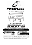
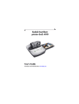
Manuel d’Installation et d’Utilisation PD4000 Series Power Control Center © 2011 Progressive Dynamics, Inc. All rights reserved. 110145 Rev F Patent Numbers: 5,687,066 - 5,600,550 - 5,982,643 - 6,184,649 - 7,782,002 tie n a e m ar e sit .co g l d e u r d yn s s n io les ive s en onib ess t Ex isp gr d ro .p w ww 507 Industrial Rd. Marshall, MI 49068 www.progressivedyn.com Progressive Dynamics, Inc. With enough AC and DC branches you’ll have plenty of options for your growing RV needs. The heart of the PD4000 is the INTELI-POWER Converter. The built-in Charge Wizard microprocessor constantly monitors the battery voltage then automatically adjusts the converter output voltage to provide the proper charging voltage for fast recharges and long-term maintenance. The intelligent way to charge and maintain your RV battery. Member The PD4000 Series POWER CONTROL CENTER offers break-through technologies that help maintain and lengthen the life of your batteries such as our patented Charge Wizard. Thank you for selecting Progressive Dynamics as your choice for your RV power needs. We’d like to welcome you to a full line of industry leading and time tested products including our newest addition to the PDI family, the PD4000 Series POWER CONTROL CENTER. Merci d’avoir choisi Progressive Dynamics pour les besoins en énergie de votre véhicule de caravaning. Nous vous souhaitons la bienvenue au moment de découvrir toute notre gamme de produits industriels leaders et qui ont passé l’épreuve du temps en ajoutant le petit nouveau de la famille PDI, le PD4000 Series POWER CONTROL CENTER. Avec le PD4000 Series POWER CONTROL CENTER vous avez accès à une technologie de pointe, tel que le système breveté « Charge Wizard » (Assistant de Charge), qui vous aidera à entretenir vos batteries et à augmenter leur durée de vie. Member Le cœur du PD4000 est le Convertisseur INTELLI-POWER. Le micro-processeur du « Charge Wizard » intégré contrôle en permanence la tension de la batterie, puis ajuste automatiquement la tension de sortie du convertisseur pour fournir la tension de charge adaptée pour recharger rapidement la batterie et la garder en bon état longtemps. Un moyen intelligent de chargement et de maintenance de votre batterie « RV » (véhicule de caravanning). Si vous avez suffisamment de circuits de dérivation CA et CC vous aurez encore plus de possibilités pour les besoins grandissant de votre « RV ». s at t ie s e m o an a rr rch n.c wa pu y ed for ved i nd e te bl ss Ex aila gre v o ea r ar w.p ww Progressive Dynamics, Inc. 507 Industrial Rd. Marshall, MI 49068 www.progressivedyn.com Numéros de brevets : 5,687,066 - 5,600,550 - 5,982,643 - 6,184,649 - 7,782,002 © 2011 Progressive Dynamics, Inc. All rights reserved. 110145F Installation and Operation Guide for PD4000 Series Power Control Center Progressive Dynamics, Inc. Table des Matières Guide d’Installation 1 Schéma de Câblage 1 Caractéristiques et Mode d’Emploi 2 Le « Charge Wizard » 2 Protection Contre un Mauvais Branchement de Batterie 2 Caractéristiques Techniques et Résolution des Problèmes 3-4 For Warranty Service Call: (269) 781-4241 Upon determination that a warranty claim exists (a defect in material or workmanship occurring under normal use and service,) the converter section shall be shipped postage prepaid to Progressive Dynamics, Inc. together with proof of purchase. The product will be repaired or replaced and returned postage prepaid. A. B. C. D. E. Name and address of the claimant; Name and model of the product; Name, year and model of the recreational vehicle in which the product was installed; Date of purchase; and Complete description of the claimed defect. V. CLAIM PROCEDURE: Upon discovery of any defect, Progressive Dynamics, Inc. shall be supplied the following information at the address listed in this manual: I. LIMITED WARRANTY: Progressive Dynamics, Inc. warrants its power control center to be free from defects in material or workmanship under normal use and service; and limits the remedies to repair or replacement. LIMITED WARRANTY III. ÉXCLUSIONS DE LA GARANTIE : Cette garantie ne s’applique pas spécifiquement à : A. Tout produit ayant été réparé ou altéré de quelque manière que ce soit par un tiers ou dans une station-service non autorisé(-e)s ; B. Des dommages causés par une tension d’entrée excessive, un usage inapproprié, négligence ou accident ; par force extérieure ; C. Tout produit ayant été connecté, installé ou ajusté ou utilisé autrement que selon les instructions fournies ou ayant un numéro de série altéré, dégradé ou supprimé ; D. Au coût de tous les services pour retirer et réinstaller le « power converter » ; et E. TOUTE PERTE DE PROFITS, D’ÉCONOMIES ATTENDUES, LA PERTE DE JOUISSANCE DE L’UTILISATION OU AUTRES DOMMAGES QUELS QU’ILS SOIENT RÉSULTANTS DE L’UTILISATION, OU DE L’IMPOSSIBILITÉ D’UTILISATION, DU PRODUIT. CELA INCLUT LES DOMMAGES À LA PROPRIÉTÉ ET, DANS LES LIMITES DE LA LOI, LES DOMMAGES POUR BLESSURES PERSONNELLES. CETTE GARANTIE REMPLACE TOUTES LES AUTRES GARANTIES, INCLUANT LES GARANTIES IMPLICITES D’APTITUDE À LA VENTE OU À UN BUT PARTICULIER. II. DURATION: This warranty shall extend for a period of two years from the original date of purchase, and is valid only within the continental limits of the United States and Canada. II. DURÉ : Cette garantie est valable sur une période de deux ans après la date d’achat effective, et n’est valide que sur les territoires des États-Unis d’Amérique et du Canada. III. WARRANTY EXCLUSIONS: This warranty specifically does not apply to: A. Any product which has been repaired or altered in any way by an unauthorized person or service station; B. Damage caused by excessive input voltage, misuse, negligence or accident; or an external force; C. Any product which has been connected, installed or adjusted or used other than in accordance with the instructions furnished, or has had the serial number altered, defaced or removed; D. Cost of all services performed in removing and re-installing the power converter; and E. ANY LOST PROFITS, LOST SAVINGS, LOSS OF USE OF ENJOYMENT OR OTHER INCIDENTAL DAMAGES ARISING OUT OF THE USE OF, OR INABILITY TO USE, THE PRODUCT. THIS INCLUDES DAMAGES TO PROPERTY AND, TO THE EXTENT PERMITTED BY LAW, DAMAGES FOR PERSONAL INJURY. THIS WARRANTY IS IN LIEU OF ALL OTHER WARRANTIES, INCLUDING IMPLIED WARRANTIES OF MERCHANTABILITY AND FITNESS FOR A PARTICULAR PURPOSE. I. GARANTIE LIMITÉE : Progressive Dynamics, Inc. garantit que ses « power control center » n’ont pas de vices de matériels ou de fabrication si ils sont utilisés et qu’il servent normalement ; l’entreprise limite les possibilités de réparation ou de remplacement. IV. PROOF OF PURCHASE: A warranty claim must be accompanied by proof of the date of purchase. GARANTIE LIMITÉE IV. PREUVE D’ACHAT : La demande de garantie doit être impérativement accompagnée de la preuve de la date d’achat. 2 2 Features and Operating Instructions 1 Wiring Diagram 1 Installation Instructions Table of Contents Progressive Dynamics, Inc. The Charge Wizard Pour e-mail du service de garantie: [email protected] 2 Si la réclamation de garantie est justifiée (vice de matériel ou défaut de fabrication apparut lors d’un usage normal), le convertisseur devra être envoyé en port prépayé à Progressive Dynamics, Inc. accompagné de la preuve d’achat. Le produit sera réparé ou remplacé et retourné en port prépayé. Reverse Battery Protection Nom et adresse du demandeur ; Nom et modèle du produit ; Nom, année et modèle du véhicule de caravaning dans lequel le produit a été installé ; Date d’achat ; et Description complète du défaut en question. 3-4 A. B. C. D. E. Technical Specs and Troubleshooting V. PROCÉDURE DE RÉCLAMATION : En cas de découverte de tout défaut, Progressive Dynamics, Inc doivent être fournis les renseignements suivants à l'adresse indiquée dans ce manuel: Page 1 Consult a licensed electrician or an RV technician for installation assistance Guide d’Installation Note: Above image may vary, depending on model. Le PD4000 series POWER CONTROL CENTER doit être installé horizontalement (la partie convertisseur vers la gauche). L’unité N’A PAS de protection d’allumage. Ne pas raccorder à un GPL ou directement sur un compartiment de batterie. Couper un trou de montage d’environ 10 3/4” de large X 7 1/4” de haut. Connectez le câblage électrique en utilisant de bonnes connections et un attache-câble de taille appropriée. Vous pouvez vous le procurer, auprès de Progressive Dynamics,Inc. Code d’Article PD812374. AC NEUTRAL (WHITE) TO CONVERTER AC NEUTRAL IN (WHITE) Pour les installations sans CC externe sectionneur POS batterie communiquer (+) pour les BATTERIE POS. + Patte. Le ALTERNE BATTERIE POS. + Patte n'est pas utilisé. (Voir schéma de câblage pour les emplacements patte) DC DECONNECTER: Pour les installations comportant un DC externe sectionneur, POS batterie communiquer (+) et BATTERIE POS. + "Patte vers le même pôle sur le sectionneur externe. Supprimer un DECONNECTER. Connectez le ALTERNE BATTERIE POS. 'À autre pôle sur le sectionneur externe. (Voir schéma de câblage pour l'emplacement des composants) L’OEM doit tester le convertisseur « POWER CONTROL CENTER » à charge pleine dans le lieu prévu de montage pour assurer une ventilation appropriée. Une mauvaise ventilation aura pour conséquence d’empêcher le convertisseur de fournir une puissance de sortie maximale. Les convertisseurs INTELI-POWER ne sont pas conçus pour des compartiments non ventilés. Le POWER CONTROL CENTER n’est pas conçu pour les lieux humides. Installez-le dans un endroit abrité et sec. AC HOT (BLACK) TO CONVERTER ALTERNATE BATTERY POS. + (DC DISCONNECT) AC IN GROUND (GREEN) TO CONVERTER JUMPER AC GROUND IN (GREEN) BATTERY POS. + AC HOT IN (BLACK) Ces disjoncteurs sont adaptés pour des disjoncteurs PRINCIPAL et DIVISIONNAIRE PRINCIPAL Divisionnaire Obturateur MAIN BREAKER (NOT SUPPLIED) ITE/Siemens—QP,QT ITE/Siemens QF3 Thomas & Betts—TB & TBBD Series MAIN BREAKER HOLD DOWN BATTERY NEG. Note: Some factory installed wiring not shown for clarity. 30A Square D—HOM, HOMT 15A GE TQLFPI Detailed Wiring Diagram Cutler Hammer/Bryant—BR,BRD Series GE—HACR GE—HACR Cutler Hammer/Bryant—BR,BRD Series Schéma de Câblage Détaillé Square D—HOM, HOMT Note: Certains câblages ne sont pas sur le schéma pour raison de clarté. BATTERIE POS. + DISJONCTEUR PRINCIPAL DE RETENUE BATTERIE NEG. - DISJONCTEURS (PAS INCLUS) 30A 15A Thomas & Betts—TB & TBBD Series GE TQLFPI ITE/Siemens QF3 ITE/Siemens—QP,QT DECONNECTER PHASE AC (NOIR) The following breakers are suitable for MAIN and BRANCH breakers MAIN Branch Filler Plate The POWER CONTROL CENTER was not designed for wet or damp locations. Install in an interior / dry location. The INTELI-POWER converters are not designed for zero clearance compartments. PHASE AC (NOIR) CONVERTISSEUR ALTERNE BATTERIE POS. + (CC DEBRANCHEZ) TERRE AC (VERT) NEUTRE AC (BLANC) TERRA AC (VERT) CONVERTISSEUR NEUTRE AC (BLANC) CONVERTISSEUR Note: l'image ci-dessus peuvent varier selon le modèle. assistance consulter un électricien qualifié ou un technicien pour l'installation RV The OEM should test the POWER CONTROL CENTER converter under full load conditions in its intended mounting location to ensure proper ventilation. Failure to provide adequate ventilation will prevent the converter from supplying full output power. DC DISCONNECT: For installations incorporating an external DC disconnect switch, connect battery POS (+) and the BATTERY POS. + lug to the same pole on the external disconnect switch. Remove the JUMPER. Connect the ALTERNATE BATTERY POS. + to other pole on the external disconnect switch. (see wiring diagram for component locations) For installations without an external DC disconnect switch connect battery POS (+) to the BATTERY POS. + lug. The ALTERNATE BATTERY POS. + lug is not used. (see wiring diagram for lug locations) The PD4000 series POWER CONTROL CENTER should be installed horizontally (converter section to the left). Unit is NOT ignition protected. Do not mount in the LP gas or the battery compartment. Cut mounting hole to approximately 10 3/4” wide X 7 1/4” high. Connect wiring system using proper connections and appropriately sized cable clamp. A closure plug kit for any unused Romex connectors may be purchased from Progressive Dynamics, Inc. Part Number PD812374. Installation Instructions Page 1 CAUTION FOR CONTINUED PROTECTION AGAINST RISK OF FIRE OR ELECTRICAL SHOCK, REPLACE ONLY WITH SAME TYPE AND RATING FUSE. Informations Complémentaires Page 2 Plusieurs options seront installées avant l’achat de votre nouveau « RV ». Cependant, vous devez connaître certaines options avant d’utiliser votre nouveau « POWER CONTROL CENTER ». The DC Section: The DC panel features up to 12 fused positions rated for up to 30 amps for accessories. Le PD4000 series est équipé d’un microprocesseur permettant des charges en quatre étapes pour assurer une recharge rapide et sure des batteries de 12 volts. Ces quatre différentes étapes : « BOOST », « NORMAL », « STORAGE » et notre mode breveté exclusif « EQUALIZE » garantissent les recharges automatiques des batteries et réduisent les besoins de maintenance (besoins en eau réduits). NORMAL MODE (mode charge normale) : La tension de sortie est de 13.6 volts CC. À cette tension, la charge est de bonne qualité et utilise peu d’eau. BOOST MODE (mode de charge rapide) : Si le convertisseur détecte une chute de la tension de la batterie en dessous du niveau préréglé, la tension de sortie est alors augmentée à 14.4 volts CC pour recharger rapidement la batterie. 12.4 0 4 8 12 16 20 24 28 32 36 40 44 48 52 56 60 68 72 76 80 RECHARGE TIME IN HOURS 12.6 STORAGE MODE 13.2 VOLTS MAINTAINS CHARGE WITHOUT GASSING OR WATER LOSS 12.8 13.0 13.2 13.4 EQUALIZE MODE (mode égaliseur) : Lorsque le Convertisseur / Chargeur est en « Storage Mode », le système se mettra automatiquement en « Equalize Mode » (14.4 volts) pendant 15 minutes toutes les 21 heures. Dans ce mode, la fonction « égalisation » de la batterie mélange l’électrolyte pour éviter la stratification et un début de sulfatation de la batterie, qui est la cause principale de détérioration des batteries. Les fabricants conseillent d’égaliser régulièrement les batteries pour éviter la sulfatation. REVERSE BATTERY PROTECTION CIRCUIT If a battery is accidentally hooked up backwards, the converter will be protected. Easily accessible ATC type fuses will blow when a battery is connected in reverse. Correct battery wiring and replace fuses with same type and rating. The LED will glow if one of the fuses blow. Appropriate fuse size is indicated on the circuit board. STORAGE MODE (mode de charge complète) : Quand le convertisseur ne détecte pas d’utilisation significative de la batterie pendant environ 30 heures la tension de sortie est réduite à 13.2 volts CC pour une utilisation d’eau minimale. En mode charge complète, le microprocesseur augmente automatiquement la tension de sortie à 14.4 volts pendant 15 minutes toutes les 21 heures. Cela aidera à réduire la sulfatation dans les plaques de batterie. NORMAL MODE 13.6 VOLTS SAFELY COMPLETES CHARGE 13.6 13.8 14.0 14.2 BOOST MODE 14.4 VOLTS RAPIDLY BRINGS RV BATTERY UP TO 90% OF FULL CHARGE. 14.8 CONVERTER OUTPUT VOLTAGE EQUALIZE MODE 14.4 VOLTS EVERY 21 HOURS FOR A PERIOD OF 15 MINUTES TO PREVENT BATTERY STRATIFICATION. IT IS IMPORTANT THAT THE FLUID LEVEL OF ANY CONNECTED BATTERIES BE CHECKED ON A REGULAR BASIS. ALL BATTERIES WILL “GAS” AND LOSE SOME FLUID WHEN CONTINUOUSLY CONNECTED TO ANY CHARGING SOURCE. ~Does not apply to “gel-cell” batteries~ CAUTION - All times and voltages provided above are approximate. - STORAGE MODE: When the converter senses that there has been no significant battery usage for 30 hours the output voltage is reduced to 13.2 volts DC for minimal water usage. When in storage mode the microprocessor automatically increases the output voltage to 14.4 volts DC for 15 minutes every 21 hours to help reduce sulfation of the battery plates. CIRCUIT DE PROTECTION DE BATTERIE INVERSÉE Si la batterie est branchée à l’envers accidentellement, le convertisseur sera protégé. Lorsque la batterie est branchée à l’envers, les fusibles de type ATC sautent. Ils sont facilement accessibles. Remplacez-les par des fusibles ATC de même type et de même calibre. Les voyants DEL s’allument si un fusible saute. Des fusibles de taille est indiquée sur la carte de circuit imprimé. 14.4 AVERTISSEMENT IL EST ESSENTIEL DE VÉRIFIER RÉGULIÈREMENT LE NIVEAU DES LIQUIDES DE TOUTE BATTERIE CONNECTÉE. LES BATTERIES VONT « DÉGAGER DES GAZ » ET PERDRE DES LIQUIDES LORSQU’ELLES SONT BRANCHÉES EN CONTINU À UNE SOURCE DE CHARGE . ~Ne s’applique pas aux batteries « gel-cell »~ NORMAL MODE: Output voltage set at approximately 13.6 volts DC. BOOST MODE: If the converter senses that the battery voltage has dropped below a preset level the output voltage is increased to approximately 14.4 volts DC to rapidly recharge the battery. The PD4000 series incorporates a microprocessor to provide a three-stage charge profile to ensure rapid, yet safe recharging of 12 volt batteries. These three separate stages BOOST, NORMAL, and STORAGE modes ensure that the battery is automatically recharged and maintained with minimum maintenance (i.e. reduced need to add water). Many options will be installed prior to the purchase of your new RV, however there are a few options that you should be aware of while operating your new POWER CONTROL CENTER. User Information Page 2 Section CC : Le panneau de DC comprend jusqu'à 12 positions protection par fusible approuvé pour jusqu'à 30 ampères pour accessoires. AVERTISSEMENT POUR UNE PROTECTION CONTRE LES INCENDIES OU LES ORAGES, NE REMPLACEZ UN FUSIBLE QUE PAR UN AUTRE DE MÊME TYPE ET DE MÊME CALIBRE . Page 3 Consult a licensed electrician or an RV technician for installation assistance AC NOTATION COPPER WIRE ONLY. NOTES C 75 MIN MAXIMUM DE SERVICE: 30 AMPS, 120V 50/60 HZ MONOPHASE LIGNE DE TERMINAUX DE TAILLE 6-14 AWG CHARGE DE TERMINAUX DE TAILLE 6-14 AWG NEUTRAL GROUND ET TAILLE 6 - 14 AWG COURT-CIRCUIT NOTE ACTUELLE: POUR UTILISATION SUR PLUS DE 120 VOLTS AC, 10000 AMPERES MAX, LIMITÉE À LA PLUS BAS INTERRUPTION CAPACITÉ DE TOUTE BREAKER INSTALLÉS LES CHARGEMENTS CONTINOUS MAXIMUM SUR LES FOCES OU LE BRANCHEMENT CIRCUITE POUR NE ESTIMATIONS DE DISJONCTEUR Add another load to the generator, this may reduce the “spikes” to an Unit has shutdown due to over voltage. acceptable level Intermittent or no Output on Generator, works on Some generators exhibit excessive voltage spikes on Contact generator manufacturer for possible defect in the generator Shore Power the AC power output, this may cause the over voltage protection to shut the unit down Low Output Replace battery Bad battery cell(s) Correct input supply voltage Input voltage not between 105-130 VAC Improve ventilation to the compartment Reduce load requirements or install larger converter Excessive load for converter Compartment gets too hot COUPLE DE DONNEES NEUTRAL / GND FIL COMBINAISONS: (1) # 12 & BRINS (1) # 14 SOLIDE (1) # 12 & BRINS (1) # 14 BRINS (1) # 12 & SOLIDE (1) # 14 BRINS (1) # 12 & SOLIDE (1) # 14 SOLIDE (2) # 14 BRINS OU (2) # 14 SOLIDE (2) # 12 BRINS OU (2) # 12 SOLIDE (2) # 10 BRINS OU (2) # 10 SOLIDE TERMINAL DE LIGNE: VOIR DISJONCTEUR NEUTRAL GROUND & BAR: #4-#6 35 IN. LBS #8 30 IN. LBS # 10 - # 14 25 EN. LBS Check air flow to the converter Correct input voltage (Converter will shut down if the input voltage exceeds 132 VAC) Check input voltage Unit has shutdown due to over voltage Allow unit to cool Unit has shutdown due to overheating Check air flow No Output Caractéristiques Techniques (Caractéristiques sujettes à changements si sans notice) Modèle Section CA Section CC Trace RV circuits for possible fault Short circuit Replace fuses with same type and rating (See page 2) (See page 2 for location) Check for reverse battery connection. Reverse battery fuses blown Check AC distribution panel for proper operation 120 VAC supply not connected Connect power supply PROBLEM POSSIBLE CAUSES ACTION TROUBLE SHOOTING GUIDE Section Convertisseur PD4045 PD4060 120 VAC 30 Amps Maximum - 7 Dérivations Circuits Max * 12 VCC 120 Amps Maximum - 12 Dérivations Circuits Max Entrée : 105-130 VAC 50/60 Hz Entrée : 105-130 VAC 50/60 Hz 725 Watts 1000 Watts Sortie : 13.6 VDC, Sortie : 13.6 VDC, 45 Amps 60 Amps Poids : 6.5 lbs Poids : 6.25 lbs * Consult local regulatory authority for possible branch circuit restrictions * Consulter les autorités locales de réglementation des éventuelles restrictions circuit de dérivation RÉSOLUTION DES PROBLÈMES PROBLÈME RÉSOLUTION DU PROBLÈME CAUSES POSSIBLES Converter Section Connectez la source d’alimentation. Model AC Section DC Section Alimentation 120 VCA non connectée. Vérifier le panneau de distribution de CA pour un bon fonctionnement. Input: 105-130 VAC 50/60 Hz 725 Watts Output: 13.6 VDC, 45 Amps Weight: 5.70 lbs Input: 105-130 VAC 50/60 Hz 1000 Watts Output: 13.6 VDC, 60 Amps Weight: 6.35 lbs PD4045 PD4060 120 VAC 30 Amps Maximum - 7 Branch Circuits Max * 12 VDC 60A Max. - 12 Branch Circuits 12 VDC 75A Max - 12 Branch Circuits (Specifications subject to change without notice) Pas de tension de sortie Fusibles de protection de branchement de batterie Vérifiez si les branchements sont inversés sur la batterie. inversée expulsés. Remplacez les fusibles par d’autres de même type et calibre (Page 2). (Voir page 2 pour l’emplacement) Court Circuit. Recherchez d’éventuels défauts sur les circuits de votre « RV ». Vérifiez la tension d’entrée. Specifications NEUTRAL/GND WIRE COMBINATIONS: (1) #12 STRANDED & (1) #14 SOLID (1) #12 STRANDED & (1) #14 STRANDED (1) #12 SOLID & (1) #14 STRANDED (1) #12 SOLID & (1) #14 SOLID (2) #14 STRANDED OR (2) #14 SOLID (2) #12 STRANDED OR (2) #12 SOLID (2) #10 STRANDED OR (2) #10 SOLID L’unité s’est arrêtée suite à une surtension. Le convertisseur s’arrête si la tension d’entrée est supérieure à 132 volts. Corrigez la tension d’entrée. Le compartiment est trop chaud. Tension de sortie faible Charge excessive pour le convertisseur. Tension d’entrée non comprise entre 105-130 VCA. Cellules de batterie en mauvais état. Tension de sortie intermittente ou inexistante sur le générateur, fonctionne branché sur une prise de quai L’unité s’est arrêtée suite à une surtension. Certains générateurs ont des pointes de tension excessives sur une sortie CA, cela peut entraîner un arrêt de protection de l’unité par surtension. Vérifiez le flux d’air vers le convertisseur. Améliorez la ventilation du compartiment. Réduisez les besoins de charge ou installez un convertisseur plus puissant. Corrigez la tension d’entrée de l’alimentation. Remplacez la batterie. Ajoutez une charge supplémentaire au générateur, cela pourrait peutêtre réduire les « pointes » à un niveau acceptable. Contactez le fabricant du générateur pour éventuel défaut de l’appareil. assistance consulter un électricien qualifié ou un technicien pour l'installation RV AC RATING COPPER WIRE ONLY. RATED 75 C MIN MAXIMUM SERVICE: 30 AMPS, 120V 50/60 HZ SINGLE PHASE LINE TERMINALS SIZE 6-14 AWG LOAD TERMINALS SIZE 6-14 AWG NEUTRAL AND GROUND SIZE 6 - 14 AWG SHORT CIRCUIT CURRENT RATING: SUITABLE FOR USE ON NO MORE THAN 120 VOLTS AC, 10,000 AMPERES MAX, LIMITED TO THE LOWEST INTERRUPTING CAPACITY OF ANY BREAKER INSTALLED LINE TERMINAL: SEE CIRCUIT BREAKER NEUTRAL BAR & GROUND: #4 - #6 35 IN. LBS #8 30 IN. LBS #10 - #14 25 IN. LBS TORQUE DATA MAXIMUM CONTINUOUS LOADS ON MAINS OR BRANCH CIRCUITS NOT TO EXCEED 80% OF THE CIRCUIT BREAKER RATINGS Page 3 Page 4 Ne pas remplacer la section convertisseur avant d’avoir vérifié les points suivants : If you should need to replace the power converter for any reason, follow these steps to safely remove the converter section. Remove screw that secures metal plate to housing. Disconnect converter wires from AC hot, NEU, and GND bar connections. Débranchez les fils du tableau CC sur le convertisseur. Débranchez les fils venant de la source de CA. Disjoncteur, Barres de connexion « NEU » (neutre), et « GND » (terre) . Make sure all power is disconnected before proceeding. 4. Remove the neutral, ground, and hot wires that lead to the converter on the AC side. Remove the converter output wires from the DC board, ground and positive. Finally unscrew the screw that holds the metal converter plate to the plastic housing. 3. Utilisez un voltmètre pour vérifier la bonne tension au disjoncteur 120 VAC que le convertisseur est connecté. Cette tension doit être comprise entre 105 et 130 volts. Retirer les fusibles de la batterie renversée et vérifier la sortie du convertisseur de la GND CONVERTISSEUR aux bornes CONVERTISSEUR POS au conseil DC. Cela devrait être 13,6 VDC. Vérifiez les fusibles de la batterie inversée. Ces fusibles ne sauteront si la batterie ou de fils de sortie DC ont été branchée à l'envers, même pour un instant. Si elles sont soufflées vérifier la polarité des connexions de la batterie avant de les remplacer. Si la sortie du convertisseur n'est pas présent et il ya ca dans le convertisseur, le convertisseur est défectueux. 1. 2. 3. 2. For factory repairs, return only the converter section. Make sure you use proper packaging to ensure the product’s safe arrival. 1. Retirez la visse de sécurité entre la plaque de métal et la housse en plastique. Si vous deviez remplacer le convertisseur de puissance pour quelque raison que ce soit, veillez à bien suivre les étapes suivantes pour enlever en toute sécurité la section convertisseur. 2. 1. Pour les réparations, n’envoyez que la section convertisseur. Assurez-vous d’utiliser un emballage adapté pour ne pas endommager le produit. 3. Use an AC voltmeter to check for the proper voltage at the 120 VAC breaker that the converter is connected to. This voltage should be between 105 and 130 volts. Remove the reverse battery fuses and check the converter output from the CONVERTER GND to the CONVERTER POS terminals on the DC board. This should be 13.6 VDC. Check the Reverse Battery fuses . These fuses will only blow if the battery or DC output leads were connected in reverse, even for a moment. If they are blown check the polarity of the battery connections before replacing them. If the Converter output is not present and there is AC to the converter , the converter is defective. Débranchez les fils neutre, de terre et du disjoncteur reliés au convertisseur côté CA. Débranchez les fils de terre, de phase et de sortie du convertisseur côté CC. Enfin, retirez la visse soutenant la plaque de métal du convertisseur à la housse en plastique. 4. 1. 2. 3. Disconnect converter wires from DC board. Assurez-vous que toutes les sources de courant sont débranchées avant de commencer. Do not replace the converter section unless the following checks have been performed: Page 4 Notes: Notes: www.progressivedyn.com Visit us on the web for other great products. 507 Industrial Rd Marshall MI 49068 P r o g r e s s i v e D y n a m i c s, I n c . P r o g r e s s i v e D y n a m i c s, I n c . 507 Industrial Rd Marshall MI, 49068 Consultez notre site web pour en savoir plus sur toutes nos gammes de produits de grande qualité.