1
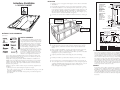
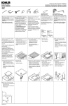
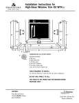
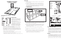
Construct a suitable installation island similar in dimension as shown in fig. A
2-105 58-5/8” [1490]
2-107 64-5/8” [1642]
2-106 70-1/8” [1781]
HYDROMASSAGE
115 volts
3/4 HP rating
Single phase
9.9 amps,
S.F. = 1.0
Protect circuit with
G.F.I. class “A”
Depth
5" (00 mm)
THERAPEUTIC
110 volts
1 HP rating
Single phase
7 amps,
Protect circuit with
G.F.I. class “A”
A
C
2 holes
11/2 (38 mm)
1 holes
1 (25 mm)
32¾” [832]
B
4"(102 mm)
8"(204 mm)
Soak/Whrl
Therp.
11/4" (32 mm)
Drain through floor
17¼” [440]
19½” [495]
61/2"
(161 mm)
SUNKEN VERSION
RECOMMENDED TOOLS & MATERIALS
2-105 L/R 60" (1524 mm)
2-106 L/R 72" (1829 mm)
2-107 L/R 66" (1676 mm)
3
SUNKEN INSTALLATION
To install any deck mounted fittings on the bath, consult the manufacturer’s
instructions. To drill holes in the deck, extreme care should be taken. Carefully
measure and mark the desired locations of the faucet centers. Apply masking
tape to the area to minimize chipping. Using a hole saw with a centering bit,
slowly drill through the bath surface from the show side.
Pump access through wall or frame
Integral tile flange version
Install the drain and overflow fitting on the bath in accordance with the manufacturer’s instructions.
Sunken version
2-105/106/107 SOMERSET
1
2
2-105 59 5/8" (1514 mm)
2-106 71 5/8" (1819 mm)
2-107 65 5/8" (1667 mm)
Installation Instructions
INSTALLATION
INTEGRAL TILE FLANGE VERSION
Bowl depth: 17 1/2"
35" (890 mm)
Outside frame ref.
BEFORE YOU BEGIN
Pipe Wrench
Clé à tuyau
Screwdrivers/
Tournevis
Caulking/
Calfeutrant
33 7/8"
(860 mm)
Tub
33 3/4"
(857 mm)
Tub
This manual covers the installation and maintenance of your new Crane Plumbing bath.
Read it through once before proceeding. After
installation the manual should be left with the
bath and consulted by the user.
Acrylic/FRP products have a high quality surface finish. Carefully inspect unit upon arrival.
Any shipping damage or shortage should be
Plumbers Putty/
Adjustable Wrench/
Level/
recorded and the carrier notified. Protective
Mastic à plomberie
Clé à molette
Niveau
storage should be provided for these fixtures.
Avoid exposing to excessive heat. Keep fixture
Vise Grips/
Hammer/
Pince-étau
Marteau
in carton until ready for final installation.
When moving shower or bath units with a handtruck they should be centred with the
back to the rear; avoid loading or flexing the wall panels.
Care must be taken to protect the surface during handling and installation. NEVER
LIFT ANY PRODUCT BY THE GRAB BAR OR WHIRLPOOL/THERAPEUTIC PIPING
OR COMPONENTS. If the unit is covered by a thin plastic film it should be removed
after final installation or prior to joining two surfaces that will be in permanent contact.
Consider the following when determining the tub location:
Will the floor be able to support the tub when filled?
An access panel should be provided for supply fittings, pump and blower (if provided).
That the dimensions of the product match those in the plan.
A wall timer must be installed out of reach of a person in the tub (whirlpool/therapeutic only).
4
Position the bath in the installation area and check the level of the unit in both
length and width. Ensure the tub rests solidly on the installed supports. Shim the
bath as required to ensure a level installation.
5
Remove the bath from the installation area and prepare a mortar mix to anchor
the tub. Trowel the mortar into the footing area of the bath and lay a 2 mil polyethylene sheet over the mass. Reset the bath into position on top of the plastic
sheet, and firmly press into place.
6
7
8
Complete the attachment of the waste piping to the drainage plumbing.
Secure the bath in its final installed position. Silicone caulk the exposed edges of
the tub.
For units requiring electrical hook-up, a separate dedicated 115 VAC, 15 Amp
circuit must be wired to the installation. Electrical codes also require a Class A
Ground Fault Circuit Interrupter (GFCI) be installed. Refer to the enclosed
equipment specific wiring instructions included with this unit.
*17 3/4" (451)
15 1/2" (394)
Tape measure/
Ruban à mesurer
1"
(25 mm)
*19 1/2" (495)
17 1/4" (440)
Hacksaw/
Scie à métaux
*17 3/4" (451)
15 1/2" (394)
Putty knife/
Couteau à mastic
11/4"
(32 mm)
*20 5/8" (524)
18 3/8" (466)
(not supplied)
Rough floor
*2 3/8" (60 mm)
1
/8" (3 mm)
2 x 4 Frame
2-105
A 30"
B 20"
C 44"
2-106
(762 mm)
(508 mm)
(1118 mm)
A 30" (762 mm)
B 211/2 (546 mm)
C 56" (1422 mm)
Shims or mortar
*2 3/8" (60 mm)
1/8" (3 mm)
2-107
A 30"
B 21"
C 50"
(762 mm)
(533 mm)
(1270 mm)
* Therapeutic models only
CARE OF SURFACE AND CLEANING
To protect glossy finish of tub follow our cleaning instructions. Do not use metal scrapers. wire brushes
or other metal tools to remove foreign material from tub. Use a sharp softwood stick to scrape off plaster.
Use turpentine or paint thinner to remove paint spots. Never use an abrasive cleaner. For regular cleaning use a non-abrasive powdered detergent such as Spic and Span. For stubborn stains use warm water
and a liquid detergent such as Handy Andy, Mr. Clean or Lestoil. Solvents such as turpentine or paint
thinner may be used without harming surface. Scouring pads of nylon, saran or polyethylene containing
no hard abrasives may be used. Restore dulled areas by rubbing with an automotive type cleaning/rubbing compound such as Dupont No. 7 followed by an application of liquid wax such as Johnson’s. Do not
use acetone, lacquer thinner, nail polish remover, or other strong solvents on bath finish.
WARRANTY
Crane Plumbing Corporate plumbing fixtures are warrantied to be free from defects in material
or workmanship under normal use and service for a period of one year from installation or two
years from manufacturing date, whichever comes first. If during that time material is found to
be efective as a result of manufacturing product will be replaced at no charge. Crane Plumbing
Corporation will not be liable for any labour, consequential or other charges in connection with
replacement of defective products, or parts, or any portion thereof.
3
Construisez une structure dîlot semblable aux dimensions montrées sur la fig. A.
HYDROMASSAGE
115V. 3/4 C/V
Monophase 9,9 amp.
F.S. = 1,0
Employez des
interrupteurs de
circuit de défaut
à la terre.
Class «A» (GFI)
Pour installer de la robinetterie encastrée sur la plate-forme du bain, consultez
le manuel d’installation. Les trous dans la plate-forme devraient être percés avec
le plus grand soin. Mesurez soigneusement et indiquez l’emplacement désirez du
centre du robinet. Appliquez du ruban de marquage à cet endroit afin de minimiser l’ébrèchement. Utilisez un emporte-pièce avec une mèche anglaise, percez
doucement à travers la surface du bain du côté apparent.
2-105 58-5/8” [1490]
2-106 64-5/8” [1642]
2-107 70-1/8” [1781]
Depth
5" (00 mm)
THÉRAPEUTIQUE
110V. 1 C/V
7 amp.
Employez des
interrupteurs de
circuit de défaut
à la terre.
Class «A» (GFI)
A
C
2 holes
11/2 (38 mm)
1 holes
1 (25 mm)
B
4"(102 mm)
8"(204 mm)
32¾” [832]
11/4" (32 mm)
Vidage à travers le plancher
Soak/Whrl
Therp.
17¼” [440]
19½” [495]
2-105 L/R 60" (1524 mm)
2-106 L/R 72" (1829 mm)
2-107 L/R 66" (1676 mm)
1
2
Accès à la pompe au mur ou au bâti
Version incluant bride de
carrelage intégrée
2-105/106/107 SOMERSET
Installez le renvoi et le trop-plein sur la baignoire selon les directives du manuel
d’installation.
Version à encaster
2-105 59 5/8" (1514 mm)
2-106 71 5/8" (1819 mm)
2-107 65 5/8" (1667 mm)
Instructions d’installation
INSTALLATION
VERSION À ENCASTER
61/2"
(161 mm)
VERSION INCLUANT BRIDE DE
CARRELAGE INTÉGRÉE
Profondeur du bassin : 17 1/2"
35" (890 mm)
Outside frame ref.
11/4"
1"
(32 mm)
(25 mm)
33 7/8"
(860 mm)
Tub
33 3/4"
MATÉRIAUX ET OUTILS RECOMMENER
(857 mm)
Tub
Ce manuel traite de l'installation et de l'entretien de
votre nouvelle baignoire Crane Plumbing. Le lire au
complet une fois avant de commencer. Après l'instalPipe Wrench
Tape measure/
Clé à tuyau
Ruban à mesurer
lation le manuel doit être garde pres de la baignoire
pour que l'utilisateur puisse le lire et le consulter.
Screwdrivers/
Caulking/
Le fini de la surface des appareils en acrylique/PRF
Tournevis
Calfeutrant
de Crane Plumbing est de qualité supérieure.
Inspecter attentivement l'appareil dès sa réception.
Plumbers Putty/
Adjustable Wrench/
Level/
Mastic à plomberie
Clé à molette
Niveau Tout dommage causé en cours de transport ou toutes
pièces manuantes doivent être inscrits et le transporter avisé. Un rangement de protection doit être
Vise Grips/
Hammer/
Pince-étau
Marteau
prévu pour ces appareils. éviter de les exposer à la
chaleur excessive. L'appareil doit rester dans la
boite en carton jusqu'a son installation finale. Lorsque vous déplacez la douche ou la
baignoire à l'aide d'un diable, elle doit être centrée avec le dos à l'arrière; il faut éviter
dechager ou de flechir les panneaux muraux.
Il faut prendre soin de protéger la surface durant la manutention et l'installation. Ne
JAMAIS soulever un produit par la barre d'appui ou la tuyauterie et les pièces du bain
tourbillon et du modèle thérapeutique. Si l'unité est recouverte d'une fine pellicule de
plasitque, celle-ci doit être enlevée après l'installation finale ou avant de joindre deux
surfaces de façon permanente.
If faut tenir compte des conditions suivantes lorsque vous déterminez l'emplacement de
la baignoire:
le plancher pourra-t-il soutenir la baignoire lorsqu'elle sera remplie;
une porte d'accès doit être prévue pour les raccords alimentation, la pompe, le système d'injection d'air et la lumière d'ambiance;
une minuterie murale doit être installée de façon que la personne dans la baignoire ne
puisse l'atteindre
*20 5/8" (524)
18 3/8" (466)
Hacksaw/
Scie à métaux
*17 3/4" (451)
15 1/2" (394)
Putty knife/
Couteau à mastic
*17 3/4" (451)
15 1/2" (394)
AVANT DE COMMENCER
*19 1/2" (495)
17 1/4" (440)
(non inclus)
Plancher non fini
4
5
6
7
8
*2 3/8" (60 mm)
1/8" (3 mm)
Placez le bain dans l’installation et vérifiez le niveau de l’unité sur la longueur
et la largeur. Assurez-vous que le bain est appuyé solidement sur les supports
installés. Égalisez le bain au besoin afin de s’assurer que l’installation est au
niveau.
Retirez le bain de l’installation et préparez une mixture de mortier pour ancrer
le bain. Étendre le mortier sous la base du bain et déposez une feuille de
polyéthylène de 2 mil sur le tout. Replacez le bain dans sa position sur la feuille
de plastique et le pressez fermement en place.
Complétez l’attachement du tuyau de vidange au système de drainage.
Installez le bain dans sa position finale. Calfeutrez les bords exposés du bain.
Pour les unités qui nécessitent un branchement électrique, un circuit séparé de
115 V., 15 ampères doit être relié à l’installation. Les codes électriques requièrent
également l’installation d’un interrupteur de circuit de défaut à la terre, classe A
(GFI). Référez-vous au manuel d’installation inclus avec l’unité pour le
branceent d’équipement spécifique.
2-105
A 30"
B 20"
C 44"
Cadre 2 x 4
2-106
(762 mm)
(508 mm)
(1118 mm)
A 30" (762 mm)
B 211/2 (546 mm)
C 56" (1422 mm)
Cales ou mortier
*2 3/8" (60 mm)
1/8" (3 mm)
2-107
A 30"
B 21"
C 50"
(762 mm)
(533 mm)
* Modèles thérapeutique
seulement
(1270 mm)
ENTRETIEN ET NETTOYAGE DES SURFACES
Pour protéger le fini lustré de la baignoire, il est recommandé de suivre attentivement les instructions de
nettoyage. Ne jamais utiliser un grattoir, une brosse métallique ni tout autre outil en métal pour enlever
les corps étrangers de la baignoire. Enlever les souillures de plâtre avec un morceau de bois mou au bord
tranchant. Éliminer les taches de peinture avec de la térébenthine ou du diluant à peinture. Ne jamais
utiliser de nettoyant abrasif. Pour les nettoyages courants, utiliser un détergent en poudre non abrasif.
Pour éliminer les taches rebelles, utiliser un détergent liquide et de l’eau tiède. Certains solvants, comme
la térébenthine et le diluant à peinture, peuvent être utilisés sans endommager le fini. On peut aussi
utiliser des tampons à récurer en nylon, en saran et en polyéthylène, pourvu qu’ils ne contiennent pas
d’abrasifs durs. On peut restaurer les surfaces dépolies en les frottant avec de la pâte à polir, puis en les
protégeant avec une couche de cire liquide. Ne jamais utiliser d’acétone, de diluant à laque, de diluant à
vernis à ongle ni d’autre solvant fort sur le fini.
GARANTIE
Pourvu qu’ils aient été utilisés normalement, les appareils sanitaires Crane Plumbing sont
garantis contre les défauts de matériaux et de fabrication pendant un an à compter de la date
d’installation, ou pendant deux ans à compter de la date de fabrication, selon la première éventualité. Si un produit vient à faire défaut durant la période de garantie, il sera remplacé sans
frais. Crane Plumbing Corporation ne peut être tenue responsable des frais de main-d’oeuvre, ni
d’aucuns frais indirects ou autres découlant du remplacement de pièces ou de produits
défectueux.