1
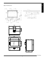
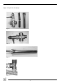
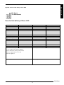
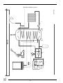
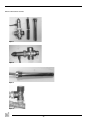
VOORWOORD ............................................................ 2
1.
INLEIDING .......................................................... 2
2.
EC CONFORMITEITSVERKLARING STORE ..... 2
3.
VEILIGHEID......................................................... 3
3.1 Algemeen............................................................. 3
3.2 Voorschriften........................................................ 3
3.3 Voorzorgsmaatregelen / veiligheidsinstructies bij
installatie ................................................................3
3.4 Aanvullende veiligheidsvoorschriften voor haards
met cv wisselaar .................................................. 3
3.5 Noodzakelijke veiligheden nader toegelicht ........... 3
3.5.1 Thermische veiligheidsklep ................................... 3
3.5.2 Het overdrukventiel .............................................. 4
3.5.3 Ontluchting .......................................................... 4
UITPAKKEN .................................................................. 5
5.
INSTALLATIE ...................................................... 5
5.1 Voorschriften........................................................ 5
5.2 Rookgaskanaal ..................................................... 5
5.3 Voorzieningen plaatsing haard .............................. 5
5.4 Plaatsen haard ..................................................... 5
5.5 Aansluiten haard .................................................. 5
6.
STOKEN.............................................................. 6
7.
OPLEVERING ..................................................... 6
8.
ONDERHOUD ..................................................... 6
9.
STORINGEN ....................................................... 6
Bijlage 1 Meegeleverde onderdelen ............................... 6
Bijlage 2 aansluitingen haard + lijntekening .................... 7
Bijlage 3 meegeleverde beveiligingen ............................ 8
Bijlage 4 Formulier voor oplevering Store H2O .............. 9
Bijlage 5 Installatieschema........................................... 10
Dik Geurts
1
N e d e r l a n d s
INHOUD.......................................................................... 1
van de minimale eisen van rendement en emissieniveaus van
verontreinigende stoffen voor verwarmingsapparaten voor vaste
brandstoffen.
VOORWOORD
Als fabrikant van haarden ontwikkelt en produceert Dik Geurts
producten volgens de hoogst mogelijke kwaliteits-, prestatieen veiligheidseisen. U kunt hierdoor rekenen op jarenlang
gebruiksplezier. Deze haard is voorzien van een CE merk.
Houtgestookte haarden die voldoen aan de essentiële eisen
uit de Europese Bouwproductenrichtlijn, waaronder eisen voor
veiligheid, milieu en energiegebruik, hebben het recht het CE
merk te dragen.
Bij de haard worden twee handleidingen geleverd: de
installatiehandleiding en de gebruikershandleiding. De
gebruikershandleiding geeft u de informatie die u nodig
heeft om de haard goed en veilig te laten functioneren. Lees
de gebruikershandleiding zorgvuldig alvorens de haard in
gebruik te nemen. U dient de gebruikershandleiding én de
installatiehandleiding zorgvuldig te bewaren. Als gebruiker
mag u uitsluitend de werkzaamheden uitvoeren die in de
gebruikershandleiding worden genoemd. Voor de overige
werkzaamheden schakelt u een vakbekwame installateur in.
De installatiehandleiding geeft u de informatie die u nodig
heeft om de haard zo te installeren dat deze goed en veilig
functioneert. Deze handleiding schenkt aandacht aan de
installatie van de haard en de daarbij geldende voorschriften.
Daarnaast treft u technische gegevens van de haard aan.
Neem bij vragen of twijfel altijd contact op met uw installateur.
U dient deze installatiehandleiding zorgvuldig te lezen en te
gebruiken.
In de handleidingen worden de volgende markeringen gebruikt
om belangrijke informatie aan te geven:
●
!
Let op
Product:
Vrijstaande, houtgestookte boiler gemaakt van plaatstaal.
Type:
Store
Van toepassing zijnde EC-richtlijnen:
89/106/EEC
Toegepaste geharmoniseerde normen:
NEN/EN-13240 NEN/EN-13240/A2
Notified body:
S.G.S. Nederland B.V.
Leemansweg 51
Postbus 5252
6827 BX Arnhem
Kenmerkende producteigenschappen
TABEL zie bestaande handleiding
Store
Uit te voeren acties
Deze instructies zijn noodzakelijk ter
voorkoming van brand, persoonlijk letsel of
andere ernstige schades.
Na oplevering dient u de gebruikershandleiding én deze
installatiehandleiding te overhandigen aan de gebruiker.
1.
INLEIDING
Gefeliciteerd met de aankoop van uw Dik Geurts haard. De
vrijstaande houtgestookte haard heeft een uitgekiend
stooksysteem dat zorgt voor een effectieve verbranding en
een optimaal rendement. De verbrandingsruimte is bekleed
met vuurvaste platen. Bovenin ligt een zogenaamde keerplaat
om het rendement te verhogen. De haard is uitgerust met een
schuif voor de luchttoevoer, een deel van de secundaire lucht
wordt continu langs de bovenkant van de ruit geleid. De haard
is uitsluitend geschikt om gestookt te worden met hout of
houtbriketten.
Brandstof
Hout
Werking
Intermitterend
Afstand tot brandbare materialen
700 mm
Emissie van
CO: 0,09 vol.% bij 13%
verbrandingsproducten
O2
Rookgastemperatuur
266 °C
Nom. direct vermogen
3,9 kW
Nom. waterzijdig vermogen
6,5 kW
Rendement
76,1 %
Rookgasstroom
10,6 g/s
Fijnstof bij 13% O2 [mg/Nm3]
33
Diameter uitgang
180 mm
Brandveiligheid
voldoet
Vrijkomen van schadelijke stoffen
geen
Oppervlaktetemperatuur
voldoet
Mechanische sterkte
voldoet
Gewicht haard
270 kg
Minimale schoorsteentrek
12 Pa
Waterinhoud
25 liter
Geschikt voor een gedeeld
Nee
schoorsteenkanaal
2.
EC CONFORMITEITSVERKLARING STORE
Rapport
EZKA/11/053-Z
De ondergetekende, vertegenwoordiger van:
Door bedrijfsinterne maatregelen is gewaarborgd dat seriematig
geproduceerde toestellen aan de essentiële eisen van de van
kracht zijnde EC-richtlijnen en de daarvan afgeleide normen
voldoen.
Deze verklaring verliest haar geldigheid als zonder schriftelijke
toestemming van DRU Verwarming B.V. wijzigingen aan het
toestel worden aangebracht.
Fabrikant:
DRU Verwarming B.V.
Postbus 1021, NL-6920 BA Duiven
Ratio 8, NL-6921 RW Duiven
Verklaart hiermee dat het door DRU uitgebrachte houtgestookte
verwarmingstoestel door zijn ontwerp en bouwwijze voldoet
aan de essentiële eisen van de Bouwproductenrichtlijn en dat
ze geproduceerd en verdeeld wordt volgens de eisen van het
koninklijk besluit van 12 oktober 2010 tot regeling
Namens DRU Verwarming B.V.
M.J.M. Gelten
Algemeen directeur
2
3.1 Algemeen
Het veilig installeren van een Dik Geurts haard met
warmtewisselaar voor vaste brandstoffen vereist specialistische
vakkennis. Deze installatiehandleiding vormt een essentieel
onderdeel in de installatie- en bedieningsinstructie voor dit type
haarden. Lees deze handleiding daarom zorgvuldig door en
volgt de instructies nauwgezet op!
In paragraaf 3.4 worden aanvullende veiligheidsvoorschriften
vermeld, specifiek voor dit type toestellen. In bijlage 4 is een
checklist opgenomen, die u helpt het toestel veilig te installeren.
!
Controleer of deze, voor de installatie noodzakelijke,
veiligheden aanwezig zijn en begin pas daarna met de
installatie!
●
Let op
●
Leest u dit hoofdstuk over veiligheid zorgvuldig door
voordat u begint met installatie of onderhoud;
Houdt u zich aan de algemeen geldende voorschriften en
de voorzorgsmaatregelen/veiligheidsinstructies in deze
handleiding.
●
●
Het in bedrijf nemen van de haard zonder de zekerheid,
dat alle veiligheidscomponenten optimaal geïnstalleerd zijn,
is niet toegestaan.
Zorg voor een goede voorziening voor ontluchting van de
warmtewisselaar. 3/8”.
Alle veiligheidscomponenten moeten na installatie goed
bereikbaar zijn voor controle- en servicedoeleinden.
Alle gebruikte componenten voor de waterzijdige installatie
moeten minimaal bestendig zijn tegen temperaturen van
110 °C.
Alle geïnstalleerde componenten, die geen deel uitmaken
van de levering door Dik Geurts, moeten aanwijsbaar
geschikt zijn voor toepassing in cv systemen.
Bij de eerste ingebruikname van de haard dienen
alle stappen van de bedieningshandleiding te worden
gerespecteerd.
De gebruiker dient duidelijk geïnstrueerd te worden over de
werking en het onderhoud van de installatie.
Adviseer de gebruiker jaarlijks een afspraak te maken voor
controle en onderhoud.
De elektrische aansluiting dient volgens de plaatselijk
geldende norm te worden te worden gerealiseerd.
●
●
●
3.2 Voorschriften
Installeer het toestel volgens de geldende Europese, nationale,
lokale en bouwkundige (installatie)voorschriften. Voor Nederland
geldt onder meer het Bouwbesluit.
●
●
3.3
●
●
●
●
●
●
●
●
●
●
●
●
●
Voorzorgsmaatregelen / veiligheidsinstructies bij
installatie
installeer en onderhoud de haard alleen als u een
vakbekwame installateur op het gebied van
houtgestookte CV toestellen bent;
plaats de haard op een vloer met voldoende draagkracht;
plaats de haard en/of de haardpijpen voor een wand van
niet brandbaar materiaal;
breng indien u brandbare materialen aantreft voldoende niet
brandbaar isolatie materiaal aan;
plaats de haard en/of de haardpijpen op minimaal 50 mm
vanaf de niet brandbare wand;
plaats de haard en/of de haardpijpen altijd op minimaal
700 mm afstand van brandbare objecten en/of materialen;
plaats de haard op een beschermende vloerplaat in geval
van een brandbare vloer. De vloerplaat van niet brandbaar
materiaal dient minimaal 300mm voor de haard uit te steken
en een minimaal 300 mm breder te zijn dan de haard;
dek de haard niet af en/of pak deze niet in met een
isolatiedeken of enig ander materiaal;
sluit de haard aan op een geschikt rookgaskanaal;
laat het rookgaskanaal vooraf inspecteren en reinigen door
een erkend schoorsteenveegbedrijf;
breng zelf geen wijzigingen aan de haard aan;
gebruik uitsluitend originele onderdelen ter vervanging;
zorg voor voldoende ventilatie in de opstellingsruimte.
3.4
!
●
●
!
Let op
Wanneer de installatie niet aan deze punten voldoet, vervalt
elke vorm van productgarantie.
3.5
Noodzakelijke veiligheden nader toegelicht
3.5.1 Thermische veiligheidsklep
Het toestel wordt volgens de norm EN 12828 beveiligd tegen
een te hoge watertemperatuur. Hiertoe is een thermische
veiligheidsklep meegeleverd.
!
Let op
De thermische veiligheidsklep dient op een ‘koele’ plaats
(< 50 °C) te worden gemonteerd en altijd goed toegankelijk
te zijn.
!
Aanvullende veiligheidsvoorschriften voor haarden
met cv wisselaar
Let op
Een minimale waterdruk van 2.0 bar moet gegarandeerd
zijn.
Wanneer de waterdruk niet gegarandeerd is, mag installatie
alleen plaatsvinden op een open expansiesysteem.
De veiligheidsklep is uitgevoerd met een zeer dunne en
kwetsbare capillaire leiding. Deze heeft als functie de druk, die
opgebouwd wordt in de voeler, over te brengen naar de klep.
Let op
Bij de installatie van een Dik Geurts haard met cv wisselaar
zijn de volgende zaken essentieel:
●
Installatie zonder de meegeleverde veiligheden is niet
toegestaan.
Dik Geurts
3
N e d e r l a n d s
Een haard van Dik Geurts wordt altijd geleverd met de
onderstaande veiligheden:
- Veiligheidswarmtewisselaar (in het toestel geïnstalleerd);
- Thermische veiligheidsklep, met vloeistofgevulde voeler
en capillaire leiding;
- Overdrukventiel, 3 bar
3.
VEILIGHEID
Hieronder volgen tips en instructies die belangrijk zijn voor de
goede werking van uw haard.
De leiding van het overdrukventiel naar de afvoer moet aan
bepaalde eisen te voldoen.
Bij een leiding met een maximale lengte van 2 meter:
- het maximale aantal bochten in deze leiding is 2;
- de minimale diameter van deze leiding is ½”;
- deze moet vrij van afsluiters en weerstanden zijn.
Wanneer de klep door beschadiging lekt, is de werking niet
meer gegarandeerd en dient de klep te worden vervangen.
!Let op
De capillaire leiding van de thermische veiligheidsklep mag nooit
geknikt, ingekort of beschadigd worden.
!
Let op
Bij
-
De uitmonding van de overstortleiding dient op een veilige
plaats te worden gemonteerd.
De uitmonding van de overstortleiding moet zo worden
gemonteerd, dat er geen gevaar voor de gebruiker kan
ontstaan. Bij het in werking treden van deze veiligheid, stroomt
water van ongeveer 100 °C uit de afvoerleiding.
een leiding met een maximale lengte van 4 meter:
het maximale aantal bochten in deze leiding is 3;
de diameter van deze leiding is ¾”;
deze moet vrij van afsluiters en weerstanden zijn.
!
Let op
Indien dit ventiel vervangen moet worden, dient een klep
met exact dezelfde specificaties te worden gemonteerd.
Het aansluiten van een thermische veiligheidsklep is
schematisch weergegeven in bijlage 4.
!
!
Let op
Monteer de afblaasleiding van het overdrukventiel buiten het
directe bereik van personen.
Het overdrukventiel dient op een toegankelijke plek te worden
gemonteerd voor periodieke tests.
Zorg ervoor dat de uitmonding van de afvoerleiding van de
thermische veiligheidsklep op doorstroming en lekkage te
controleren is.
!
3.5.3 Ontluchting
Een goede ontluchting is van groot belang voor de werking van
het systeem.
Ga voor een goede ontluchting als volgt te werk:
- aan de achterzijde van het toestel bevindt zich een 3/8”
binnendraad sok;
- monteer hier een ontluchtinrichting;
- voorzie het systeem in de aanvoer en retour van
ontluchtmogelijkheden.
Let op
De aansluitleiding voor de thermische veiligheidsklep moet
vorstvrij worden aangelegd. Bevriezing moet te allen tijde
worden voorkomen.
3.5.1.2 De werking van de thermische veiligheidsklep.
De thermische veiligheidsklep is een op koud leidingwater
werkende veiligheid. Wanneer de temperatuur aan de voeler
van de klep te hoog wordt, opent de klep. In dat geval
wordt koud leidingwater door de koelspiraal gestuurd om de
overtollige warmte af te voeren. Vermenging van leidingwater en
water uit het verwarmingssysteem is hierbij uitgesloten, omdat
de koelspiraal gescheiden is van de ketel.
De veiligheidsklep opent bij 95 °C (+/-3 °C) en zorgt ervoor,
dat de keteltemperatuur onder de 110 °C blijft.
!
Let op
Wanneer lucht zich ophoopt in het systeem, kan de pomp
het cv water niet goed transporteren.
De temperatuurbeveiliging kan dan, vanwege te hoge
temperaturen, in werking treden, voordat het toestel warm
water aan het systeem afgeeft.
3.5.4 Droogkookbeveiliging
3.5.2 Het overdrukventiel
Een te hoog oplopende druk in het systeem is schadelijk.
Om dit te voorkomen, is bij het toestel een overdrukventiel
meegeleverd.
!
Let op
!
Let op
In een half met water gevulde haard, kan zich stoom
vormen, wat tot gevaarlijke situaties kan leiden.
Dit is het geval wanneer radiatoren, buffervaten of andere,
met water gevulde, elementen binnen het systeem, zich onder
het niveau van de haard bevinden. Plaats ter voorkoming een
beveiliging, die het waterniveau controleert.
Let op
Het overdrukventiel moet altijd worden geïnstalleerd! Zonder
deze klep kan een veilige werking van het systeem niet
worden gegarandeerd.
Houd voor een veilige en correcte werking van het
overdrukventiel rekening met het volgende:
- sluit het overdrukventiel aan op de haard;
- gebruik hiervoor een leiding met een minimale diameter
van ½”;
- afsluiters en weerstanden in de leiding zijn niet toegestaan;
- gebruik maximaal één bocht.
4
UITPAKKEN
5.4
Schenk aandacht aan de onderstaande punten bij het
uitpakken van de haard:
●
Controleer het toestel op transportschade, plaats nooit een
beschadigde haard;
●
Controleer of de doos met onderdelen compleet is.
●
In Bijlage 1 / Tabel 1 staat vermeld over welke onderdelen
u na het uitpakken dient te beschikken;
●
Door het transport kunnen onderdelen verschoven zijn,
controleer de ligging van de keerplaat en vuurvaste platen.
(zie handleiding).
●
Controleer de werking van luchtschuif, deursluiting en het
eventuele draaimechanisme;
●
Verwijder eventueel achtergebleven straalgrit uit de
luchtschuif;
●
Neem zo nodig contact op met uw leverancier;
●
Voer de verpakking af via de reguliere weg.
!
●
●
●
●
●
●
●
●
5.
INSTALLATIE
●
5.1
●
●
Voorschriften
Installeer de haard volgens de geldende Europese,
nationale, lokale en bouwkundige (installatie)
voorschriften.
Houdt u zich aan de voorschriften/instructies zoals
vermeld in deze handleiding.
●
●
●
●
●
5.2
●
●
●
●
●
●
●
●
●
●
●
Plaatsen haard
●
Rookgaskanaal
Voor het rookgaskanaal gelden de volgende eisen:
het rookgaskanaal moet van tevoren geïnspecteerd worden
door een specialist;
het rookgaskanaal dient geschikt te zijn voor aansluiting van
een houtgestookt toestel;
de haard dient te worden aangesloten op een enkel,
ongedeeld rookgaskanaal;
het rookgaskanaal moet schoon zijn;
het rookgaskanaal moet gasdicht zijn;
de diameter van het rookgaskanaal moet 180 mm zijn;
de trek van het rookgaskanaal moet minimaal 12 Pascal
zijn;
in een (te) sterk trekkend kanaal dient zonodig een
rookgasklep worden aangebracht;
haardpijpen moeten afwaterend naar de haard worden
geplaatst;
het rookgaskanaal dient zelfdragend te zijn en mag niet op
de haard rusten;
Let op
Breng geen wijzigingen aan de haard aan;
plaats de haard op een vloer met voldoende draagkracht;
plaats de haard en/of de haardpijpen tegen een wand van
niet brandbaar materiaal;
plaats de haard en/of de haardpijpen op minimaal 50 mm
vanaf de wand;
plaats de haard en/of de haardpijpen altijd op minimaal
700 mm afstand van brandbare objecten en/of materialen;
plaats de haard op een brandwerende vloerplaat die volgens
de geldende norm voor de haard uitsteekt als deze op een
vloer van brandbaar materiaal komt te staan;
dek de haard niet af en/of pak deze niet in met een
isolatiedeken of enig ander materiaal;
houdt u zich aan de eisen voor het rookgaskanaal zoals
genoemd in paragraaf 5.2.
Bepaal de plaats van de haard; de afmetingen zijn
aangegeven in bijlage 2.
Plaats zo nodig de vloerplaat.
Zet de haard op de bestemde plek.
Controleer of de vuurvaste platen en de keerplaten in de
haard goed geplaatst zijn (zie gebruikshandleiding).
Verbeter zo nodig de positie van de platen.
Sluit de haard aan op het rookgaskanaal.
Plaats een optioneel verkrijgbaar inspectie-element, indien
de afvoerpijp niet verwijderd kan worden bij onderhoud
aan de kachel. In dit halve meter afvoerelement zit een
inspectieluikje om het eventuele roet te verwijderen wat
bovenop de stalen keerplaat in de kachel ligt.
5.5 Aansluiten haard
Ga bij het aansluiten van de haard als volgt te werk (voor een
tekening van de aansluitingen zie bijlage 2):
●
sluit de thermische veiligheidsklep (bijlage 3 figuur 1) aan op
de aanvoer (D) van de koelspiraal. Zorg dat de pijl op de
veiligheidsklep richting de aansluiting van de koelspiraal
wijst (zie bijlage 2).
●
sluit de afvoer van de koelspiraal (E) aan op de waterafvoer
of riolering;
●
plaats de dompelhuls voor de voeler (figuur 3) van de
thermische veiligheidsklep in de watermantel. Dit is de sok
links boven op de achterkant van de haard.
●
schuif de voeler van de thermische veiligheidsklep (A) in de
zojuist aangebrachte dompelhuls. Borg de voeler met de
schroef die in de dompelhuls zit (figuur 3).
●
sluit de retour van het te verwarmen CV-water aan op de
3/4’’ sok; deze bevindt zich aan de onderzijde van de
watermantel (zie bijlage 2) (G).
●
sluit de aanvoer van het verwarmde CV-water aan op de
één van de aanvoeraansluitingen (3/4’’ sok). (zie bijlage 2)
5.3 Voorzieningen plaatsen haard
Voor het plaatsen van een vrijstaande haard met directe warmte
èn warm water als output, dienen de volgende voorzieningen,
op de plaats van de haard, aanwezig te zijn:
●
een waterleidingaansluiting ten behoeve van de
veiligheidswarmtewisselaar;
●
een aansluiting op de waterafvoer of riolering ten behoeve
van de veiligheidswarmtewisselaar en het overdrukventiel.
●
Let op: Houd rekening met een temperatuur van 100 °C in
het afvoersysteem.
●
een aanvoer en retour van het cv-systeem;
●
een mogelijke elektriciteitsaansluiting bij gebruik van de
pomp (deze pomp is een essentieel onderdeel van het
systeem, maar wordt niet meegeleverd!).
Er zijn twee aanvoeraansluitmogelijkheden:
aanvoer 1 (C) zit bovenin de watermantel en aanvoer 2 (F)
zit onderaan de watermantel. Deze laatste aanvoer haalt het
warme water uit de bovenkant van de watermantel door middel
van een buis die door de watermantel loopt. Het aanvoerwater
van aanvoer 2 is daardoor minder heet dan het water uit
aanvoer 1. Afhankelijk van de retourtemperatuur is de maximale
temperatuur die uit aanvoer 2 gehaald kan worden 80 °C.
Dik Geurts
5
N e d e r l a n d s
4.
●
●
Voor maximale prestatie wordt geadviseerd aanvoer 1 te
gebruiken. Als de hoge aanvoertemperatuur niet nodig is,
kan aanvoer 2 gebruikt worden zodat alle leidingen onder
aan de haard zitten.
plaats het overdrukventiel (figuur 4) in de afvoer CV-leiding
van de haard en sluit deze aan op de waterafvoer of
riolering (zie ook hoofdstuk 3.5.2).
!
●
8.
ONDERHOUD
In de Gebruikershandleiding wordt in Hoofdstuk 6, Onderhoud,
een aantal tips/instructies gegeven voor het onderhoud van de
haard. Tevens is vermeld hoe een aantal onderdelen vervangen
kan worden.
Let op
9.
STORINGEN
In de Gebruikershandleiding, hoofdstuk 7, staat een tabel met
een overzicht van storingen die kunnen optreden, de mogelijke
oorzaak en de oplossing.
Tussen het overdrukventiel en de haard mogen geen
afsluiter of andere weerstanden geplaatst zijn!
Bijlage 1 Meegeleverde onderdelen
In de onderstaande tabel staan de onderdelen vermeld die met
het toestel worden meegeleverd.
5.6. Retourtemperatuurbewaking.
Om te voorkomen dat de warmtewisselaar te veel vervuild
is het belangrijk de haard zo snel mogelijk boven de
condensatietemperatuur van de rookgassen te brengen
en te houden. Dit dient te gebeuren doormiddel van een
retourtemperatuurbewaking welke ervoor zorgt dat de
retourtemperatuur naar de haard niet onder de 60˚C komt.
Een dergelijke unit is bij Dik Geurts te bestellen onder bestelnr.
45256.Het toepassen van een dergelijk systeem is verplicht om
de goede werking van dit product te garanderen. In bijlage 5 is
een voorbeeld installatieschema afgebeeld.
Tabel 1:
De verschillende componenten in dit schema zijn:
a) Retourtemperatuurbewaking(pompunit).
b) Expansievat.
c) Ontluchter.
d) Overdrukventiel(3bar)
e) Thermisch laadventiel.
f) Watertoevoer.
g) Circulatiepomp cv-systeem.
6.
STOKEN
!
●
●
Wijs de gebruiker op de noodzaak de warmtewisselaar te
reinigen (zie de gebruikershandleiding, hoofdstuk 2.1).
Let op
Een Dik Geurts haard met CV wisselaar mag nooit zonder
water worden gestookt!
Deze toestellen moeten eerst met water gevuld en ontlucht
worden en mogen pas in gebruik genomen worden als de
functionele installatie volledig afgerond is.
Zie de Gebruikershandleiding, hoofdstuk 5, voor het aansteken
en stoken van de haard.
7.
OPLEVERING
U dient de gebruiker vertrouwd te maken met de haard. U dient
haar/hem te instrueren over onder meer de ingebruikname, het
stoken en het onderhoud.
●
Instrueer de gebruiker over de haard.
●
Wijs er bij ingebruikname op, dat
●
bij de eerste keer stoken vluchtige componenten uitdampen
uit lak, materialen e.d.;
●
de ruimte goed wordt geventileerd.
●
Wijs op de noodzaak om het rookgaskanaal minstens
één keer per jaar te laten inspecteren en reinigen door een
specialist.
●
Overhandig de gebruiker de gebruikershandleiding en de
installatiehandleiding (de installatiehandleiding dient bij het
toestel bewaard te blijven).
6
Onderdeel
Aantal
Installatiehandleiding
1
Gebruikershandleiding
1
Handschoen
1
Asschep
1
Spuitflacon ruitenreiniger
1
Spuitbus met hittebestendige lak
1
Overdrukventiel
1
Thermisch laadventiel
1
Schoonmaakborstel
1
N e d e r l a n d s
Bijlage 2 Aansluiting haard
196
780
180
830
390
800
570
440
Dik Geurts
7
Bijlage 3 Meegeleverde beveiligingen
Figuur1
Figuur2
Figuur3
14
Figuur4
8
N e d e r l a n d s
Bijlage 4 Formulier voor oplevering Store H2O
Dik Geurts
The Netherlands
Formulier voor oplevering Store H2O
Inbouw datum:
Klant:
…………………………………..
Straat:
………………………………….. Huisnummer:
……………………………..
Postcode:
………………………………….. Plaatsnaam:
……………………………..
Schoorsteenhoogte:
……………………….….m
Doorsnede:
…………………………m
Materiaal :
…………………………….
Kap?, zo ja type:
…………………………..
Hoogte boven nok?
…………....……………..m
Klep?:
…………………………..
Reinigingsmogelijkheid:
……………………………..
Luchtoevoer:
………………………………
Ø cv aansluiting:
…………………………mm
Pompunit(verplicht)
………………………………..
Ø water aansluiting:
…………………………mm
Regeltemperatuur pompunit
…………………………….°C
Verklaring van oplevering:
Firmastempel:
De gebruiker verklaart hiermee dat het toestel
werkend is opgeleverd en hem/haar is uitgelegd
hoe het toestel te gebruiken en te onderhouden:
Datum en handtekening gebruiker:
Datum en handtekening installateur:
Dik Geurts
9
F
95˚C
E
D
10
A
60˚C
C
BB
Store
G
30-05-2012
Bijlage 5 Installatieschema
PREFACE .................................................................. 12
1.
INTRODUCTION ............................................. 12
2.
EC DECLARATION OF CONFORMITY STORE 12
3.
SAFETY............................................................. 13
3.1 General .............................................................. 13
3.2 Regulations ........................................................ 13
3.3 Precautions/safety instructions during installation.13
3.4 Additional safety regulations for stoves with CH
heat exchanger................................................... 13
3.5 Required safeguards explained in more detail ..... 13
3.5.1 Thermal safety valve .......................................... 13
3.5.2 Overpressure relief valve .................................... 14
3.5.3 De-aeration ....................................................... 14
REMOVING THE PACKAGING .................................. 15
5.
INSTALLATION ................................................ 15
5.1 Regulations ........................................................ 15
5.2 Flue duct.......................................................... 145
5.3 Provisions for placing the fire ............................. 15
5.4 Placing the fire .................................................. 15
5.5 Connecting the fire ........................................... 15
6.
BURNING .......................................................... 16
7.
DELIVERY ........................................................ 16
8.
MAINTENANCE................................................. 16
9.
MALFUNCTIONS ............................................. 16
Appendix 1 Parts supplied ........................................... 16
Appendix 2 connections fire + line drawing ................. 17
Appendix 3 safeguards supplied ................................. 18
Appendix 4 Form for final delivery of Store H2O .......... 19
Appendix 5 Installation overview .................................. 20
Dik Geurts
11
E n g l i s h
CONTENT..................................................................... 11
PREFACE
Dik Geurts, a fire manufacturer, develops and produces
products that comply with the highest quality, performance
and safety requirements. This will enable you to enjoy using
this product for many years to come. This fire is provided with
a CE mark. Wood burning fires that comply with the essential
requirements of the European Construction Products Directive,
including the requirements for safety, environment and energy
consumption, are entitled to carry the CE mark.
The fire is supplied with two manuals: the installation manual
and the user manual. The user manual will provide you with the
information that is required for a good and safe operation of the
fire. Carefully read the user manual prior to using the fire. Keep
the user manual AND the installation manual in a safe place. As
a user you are only entitled to perform the work described in
the user manual. Any other work requires a competent installer.
The installation manual will give you the information you need
to install the fire in such a way that it will operate properly and
safely. This manual discusses the installation of the fire and the
regulations that apply to the installation. It also provides you
with the technical specification of the fire. In case of questions
or doubts, please contact your installer.
Please carefully read and use this installation manual.
The following symbols are used in the manual to indicate
important information:
●
Product:
Free-standing, wood burning boiler made from steel plate.
Type:
Store
Applicable EEC directives:
89/106/EEC
Applied harmonized standards:
NEN/EN-13240 NEN/EN-13240/A2
Notified body:
S.G.S. Nederland B.V.
Leemansweg 51
Postbus 5252
6827 BX Arnhem
Distinguishing product features
TABLE see existing manual
Store
!
Wood
Operation
Intermittent
Distance from combustible materials 700 mm
Emission of
Actions to be performed
Caution
Fuel
You need these instructions to prevent fire,
personal injury or other serious damages.
CO: 0.09 vol.% at 13%
combustion products
O2
Flue gas temperature
266 °C
Nom. direct output
3.9 kW
Nom. output at water side
6.5 kW
Efficiency
76.1 %
After delivery, you should give the user manual and this
installation manual to the user.
Flue gas flow
1.
INTRODUCTION
Congratulations on your purchase of this Dik Geurts fire. The
free-standing wood burning fire has an ingenious burning
system which ensures effective combustion and optimum
efficiency. The combustion chamber is lined with chamotte.
At the top you will find a so-called baffle plate to increase the
efficiency. The fire is equipped with a slide for air supply. Part
of the secondary air is continuously guided along the top of the
glass pane. The fire is only suitable to be filled with wood or
wood briquettes.
Diameter exit
180 mm
Fire safety
compliant
Release of harmful substances
none
Surface temperature
compliant
Mechanical strength
compliant
Weight of fire
270 kg
Minimum chimney draught
12 Pa
Water volume
25 litres
Suitable for a shared chimney
No
Report
EZKA/11/053-Z
2.
Fine dust at 13% O2
EC DECLARATION OF CONFORMITY STORE
10.6 g/s
[mg/Nm3]
33
The undersigned, representative of:
Internal measures by the company guarantee that massproduced appliances comply with the essential requirements of
the prevailing EEC directives and the standards derived from
them.
This declaration will lose its validity if adjustments are made
to the appliance, without prior written permission by DRU
Verwarming B.V..
Manufacturer:
DRU Verwarming B.V.
PO Box 1021, NL-6920 BA Duiven
Ratio 8, NL-6921 RW Duiven
Hereby declares that the DRU issued wood fired heating
appliance was designed and constructed in such a way that
the appliance complies with the essential requirements of the
Construction Products Directive and that it is produced and
distributed in accordance with the requirements of the Belgian
Royal Decree of 12 October 2010 for the regulation of minimum
requirements concerning the efficiency and emission levels of
polluting substances for solid fuel heating appliances.
On behalf of DRU Verwarming B.V.
M.J.M. Gelten
General Director
12
3.1 General
Safe installation of a Dik Geurts fire with heat exchanger for
solid fuels requires specialist know-how. This installation manual
is an essential part of the installation and operation instructions
for this type of fires. Therefore, please read this manual
carefully and observe all instructions!
Section 3.4 states additional safety regulations, specifically for
this type of appliances. Appendix 4 includes a check list that
will help you to install the appliance safely.
!
Check whether these safeguards, which are necessary for
the installation, are present and only then start performing
the installation!
Caution
●
Carefully read this chapter on safety, before you start
performing installation or maintenance work;
Please observe the general regulations and the precautions/
safety instructions in this manual.
●
●
Taking the stove in operation without the certainty that all
safety components have been installed optimally, is
prohibited.
Make sure there is a good provision for the aeration of the
heat exchanger. 3/8”.
After installation, all safety components should be easily
accessible for inspection and service purposes.
All components used for the installation at the water side
should at least be resistant to a temperature of 110 °C.
All installed components that are not part of Dik Geurts’
scope of delivery, must be demonstrably suitable for
application in CH systems.
When the appliance is used for the first time, all steps of the
operating manual must be observed.
The user must be clearly instructed about the operation and
maintenance of the installation.
Recommend the user to make annual appointments for
inspection and maintenance.
The electrical connection must be realized in accordance
with the locally applicable standard.
●
●
●
●
3.2 Regulations
Please install the appliance in accordance with the applicable
European, national, local and constructional (installation)
regulations.
●
●
3.3
●
●
●
●
●
●
●
●
●
●
●
●
●
Precautions/safety instructions during installation
you should only install and maintain the fire if you are a
competent and recognised wood burning CH appliances
fitter;
mount the fire on a floor of sufficient load-bearing strength;
place the fire and/or the flue pipes in front of a wall made of
non-combustible material;
if you discover flammable materials apply sufficient
heat-resistant isolation material;
place the fire and/or the flue pipes at least 50 mm away
from the non-combustible wall;
always place the fire and/or the flue pipes at a minimum
distance of 700 mm from combustible objects and/or
materials;
mount the fire on a protective floor plate, in case of a
combustible floor. The floor plate made of non-combustible
material should extend at least 300mm at the front of the
fire, and it should be at least 300 mm wider than the fire;
do not cover the fire and/or do not wrap it in an insulation
blanket or any other material;
connect the fire to a suitable flue duct;
have the flue duct inspected and cleaned in advance, by a
certified chimney sweeping company;
do not make any changes to the fire yourself;
only replace parts by original parts;
make sure there is sufficient ventilation in the room where
the fire is installed.
3.4
!
●
●
!
Caution
If the installation does not comply with these points, any
form of product warranty will become invalid.
3.5
Required safeguards explained in more detail
3.5.1 Thermal safety valve
In accordance with standard EN 12828, the appliance is
protected against a water temperature that is too high. For this
purpose, a thermal safety valve is supplied.
!
Caution
The thermal safety valve must be mounted on a ‘cool’
location (< 50 °C) and must always be easily accessible.
!
Additional safety regulations for stoves with
CH heat exchanger
Caution
A minimum water pressure of 2.0 bar must be guaranteed.
If the water pressure is not guaranteed, installation should only
take place on an open expansion system.
The safety valve is made with a very thin and fragile capillary
tube. It function is to transfer the pressure that is being
accumulated in the detector to the valve.
Caution
When installing a Dik Geurts fire with CH heat exchanger,
the following is essential:
●
Installation without the supplied safety devices is not
permitted.
If the valve leaks due to damage, the operation is no longer
guaranteed and the valve should be replaced.
Dik Geurts
13
E n g l i s h
A Dik Geurts fire is always supplied with the following
safeguards:
- Safety heat exchanger (installed in the appliance);
- Thermal safety valve, with fluid filled detector and
capillary tube;
- Pressure relief valve, 3 bar
3.
SAFETY
Below you will find tips and instructions for a good operation of
your fire.
In
-
!Caution
The capillary tube of the thermal safety valve should never be
kinked, shortened or damaged.
!
Caution
!
The exit of the overflow pipe, must be mounted at a safe
location.
!
Caution
3.5.3 De-aeration
A good de-aeration is very important for the system’s operation.
For a good de-aeration, proceed as follows:
- at the back of the appliance you will find a 3/8” female
thread bush;
- mount a de-aeration device here;
- provide the system in the supply and return of de-aeration
facilities.
Make sure the exit of the discharge pipe of the thermal
safety valve can be checked for flow-through and leakage.
Caution
This connection pipe for the thermal safety valve must be
installed in a location where no frost can occur. Freezing
must be prevented at all times.
3.5.1.2 Operation of the thermal safety valve.
The thermal safety valve is a voltage free safeguard working on
cold mains water, which monitors the boiler temperature. When
the temperature at the valve’s detector becomes too high, the
valve will open. In that case, cold mains water is sent through
the cooling coil in order to discharge excess heat. Mixing of
mains water and water from the heating system is not possible,
as the cooling coil is separated from the boiler.
The safety valve opens at 95 °C (+/-3 °C) and makes sure that
the boiler temperature remains below 110 °C.
!
Caution
If air accumulates in the system, the pump will be unable to
transport the CH water properly.
In that case, because of temperatures that are too high,
the temperature safeguard may be activated before the
appliance supplies hot water to the system.
3.5.4 Boiling-dry safeguard
3.5.2 Overpressure relief valve
If the pressure gets too high, this is harmful to the system.
In order to prevent this, the system is supplied with an
overpressure relief valve.
!
Caution
Mount the blow-off pipe of the safety valve outside of the
direct reach of persons.
The safety valve must be mounted on an accessible location for
periodic tests.
The connection of a thermal safety valve is displayed in a
diagram in appendix 4.
!
Caution
If this valve has to be replaced, a valve with the exact same
specifications must be mounted.
The exit of the overflow pipe should be mounted in such a way,
that no hazard can occur for the user. When this safeguard is
activated, water at approximately 100 °C will flow out of the
discharge pipe.
!
case of a pipe with a maximum length of 4 metres:
the maximum number of bends in this pipe is 3;
the minimum diameter of this pipe ¾”;
it may not have any valves and resistors.
!
Caution
In a fire half-filled with water, steam can be generated,
which could lead to dangerous situations.
This will be the case when radiators, buffer vessels or other
water-filled elements within the system are below the level
of the stove. In order to prevent this, place a safeguard that
monitors the water level.
Caution
The overpressure relief valve should be installed at all
times! Without this valve, it is impossible to guarantee a
safe operation of the system.
For a safe and correct operation of the overpressure relief
valve, take the following into account:
- connect the overpressure relief valve to the fire;
- for this, use a pipe with a minimum diameter of ½”;
- valves and resistors are not allowed in the pipe;
- use only one bend maximum.
The pipe from the overpressure relief valve to the discharge
must comply with certain requirements.
In case of a pipe with a maximum length of 2 metres:
- the maximum number of bends in this pipe is 2;
- the minimum diameter of this pipe ½”;
- it may not have any valves and resistors.
14
REMOVING THE PACKAGING
5.4
Pay attention to the following aspects whenremoving the fire’s
packaging:
●
Check the appliance for transportation damage, never
install a damaged fire;
●
Check if the box with parts is complete.
●
In Appendix 1 / Table 1 you can see which parts you
should have after removing the packaging;
●
As some part may have shifted in transit, check the position
of the baffle plate and the charmotte plates. (see manual).
●
Check the operation of the air slide, door closure and, if
applicable, the rotation mechanism;
●
Remove any remaining blasting grit from the air slide;
●
For this, contact your supplier;
●
Dispose of packaging in accordance with local regulations.
5.
5.1
●
●
!
●
●
●
●
●
●
●
INSTALLATION
●
Regulations
Please install the fire in accordance with the applicable
national, local and constructional (installation) regulations.
Observe the regulations/instructions in this manual.
●
●
5.2
●
●
●
●
●
●
●
●
●
●
●
Placing the fire
●
Flue duct
The following requirements apply to the flue duct:
the flue duct must be inspected in advance by a specialist;
the flue duct must be suitable for connection to a wood
burning appliance;
the fire must be connected to a single, unshared flue duct;
the flue duct must be clean;
the flue duct must be gastight;
the flue duct’s diameter must be 180 mm;
the draught in the flue duct must be at least 12 Pascal;
in case of a duct with a draught that is too strong, it may be
necessary to install a flue valve;
flue pipes must be placed in such a way that they drain
towards the fire;
the flue duct must be self-supporting and may not rest on
the fire;
●
●
●
●
Caution
do not make any changes to the fire;
mount the fire on a floor of sufficient load-bearing strength;
place the fire and/or the flue pipes against a wall made of
non-combustible material;
place the fire and/or the flue pipes at least 50 mm away
from the wall;
always place the fire and/or the flue pipes at a minimum
distance of 800 mm from combustible objects and/or
materials;
place the fire on a fire-resistant floor plate extending in front
of the fire in accordance with the applicable standard, if it is
placed on a floor made of combustible material;
do not cover the fire and/or do not wrap it in an insulation
blanket or any other material;
observe the requirements for the flue gas channel, as stated
in paragraph 5.2.
Determine the location of the fire; the dimensions can be
found in appendix 2.
If necessary, place the floor plate.
Place the fire in its intended location.
Check if the chamotte plates and the baffle plates are
placed correctly in the fire (see user manual).
If necessary, correct the position of the plates.
Connect the fire to the flue duct.
Place an optionally available inspection element, if the flue
pipe cannot be removed during maintenance. This 50cm
flue element contains an inspection hatch for the removal of
possible soot located on top of the steel baffle plate in the
fire.
5.5 Connecting the fire
When connecting the fire, proceed as follows (for a drawing of
the connections, see appendix 2):
●
connect the thermal safety valve (appendix 3 figure 1) to the
supply (D) of the cooling coil. Make sure the arrow on the
safety valve points towards the connection of the cooling
coil (see appendix 2).
●
connect the discharge of the cooling coil (E) to the water
discharge or sewer;
●
place the plunger bush for the detector (figure 3) of the
thermal safety valve in the water jacket. This is the sock (A)
at the top left on the back of the fire.
●
slide the detector of the thermal safety valve in the plunger
bush just mounted. Secure the detector with the screw
located in the plunger bush (figure 3).
●
connect the return of the CH water to be heated to the
3/4’’ socket; it is located at the bottom of the water jacket
(see appendix 2) (G).
●
connect the supply of the heated CH water to one of the
supply connections (3/4’’ socket). (see appendix 2)
5.3 Provisions for placing the fire
In order to place a free-standing fire with an output of direct
heat AND hot water, the following provisions should be
available on the location of the fire:
●
a water mains connection for the benefit of the cooling
system;
●
a connection to the water discharge or sewerage for the
benefit of the cooling system and the overpressure relief
valve.
●
Caution: Take a temperature of 100 °C in the discharge
system into account.
●
a supply and return for the CH system;
●
a possible power connection when the pump is used (this
pump is an essential part of the system, but is not part of
the scope of delivery!).
There are two options for connecting the supply:
supply 1 (C) at at the top of the water jacket and supply 2 (F) is
at the bottom of the water jacket. The latter supply retrieves the
hot water from the top of the water jacket by means of a tube
running through the water jacket. The supply water from supply
2 is therefore less hot than the water from supply 1. Depending
on the return temperature, the maximum temperature that can
be retrieved from supply 2 is 80 °C.
Dik Geurts
15
E n g l i s h
4.
●
For a maximum performance, we recommend using supply
1. If the high supply temperature is not needed, supply 2
can be used so that all pipes are at the bottom of the fire.
●
place the overpressure relief valve (figure 4) in the CH
discharge pipe of the fire and connect it to the water
discharge or sewer (also see chapter 3.5.2).
!
8.
MAINTENANCE
There are a number of tips/instructions on the maintenance of
the fire in Chapter 6, Maintenance, of the User Manual. This
also explains how a number of parts can be replaced.
9.
MALFUNCTIONS
In chapter 7 of the User manual you will find an overview of
malfunctions that might occur, the possible causes and the
remedies.
Caution
Between the overpressure relief valve and the fire, no valves
or other resistors may be placed!
Appendix 1 Parts supplied
In the following table you can find the parts that are supplied
with the appliance.
5.6. Return temperature monitoring
In order to prevent the heat exchanger from becoming too
contaminated, it is important to bring the fire as quickly as
possible above the condensation temperature of the flue gases
and to keep it at that temperature. This should be done by
means of return temperature monitoring, which will make sure
that the return temperature to the fire does not get below 60˚C.
Such a unit can be ordered at Dik Geurts under order no.
45256. Application of such a system is necessary in order to
guarantee a proper operation of this product. In appendix 5 you
can see an example installation diagram.
Table 1:
Part
The various components in this diagram are:
a) Return temperature monitor (pump unit).
b) Expansion vessel.
c) De-aerator.
d) Overpressure valve (3 bar)
e) Thermal load valve.
f) Water supply.
g) Circulation pump CH system
6.
BURNING
!
●
●
Caution
A Dik Geurts stove with CH heat exchanger by never be
fired without water!
These appliances should first be filled with water and
de-aerated, and may only be taken into operation when the
functional installation has been fully completed.
See the User Manual, chapter 5, for lighting and burning the
fire.
7.
DELIVERY
You must explain to the user how to operate the fire. You
should instruct her/him for instance on using the appliance for
the first time, heating and maintenance.
●
Instruct the user about the use of the fire.
●
When the appliance is put into operation, point out that
●
when the fire is heated up for the first time, volatile
components evaporate from paint, materials, etc.;
●
the room should be well ventilated.
●
Point out that the flue duct should be inspected and cleaned
at least once per year, by a specialist.
●
Give the user manual and installation manual to the user (the
installation manual should be kept near the appliance).
●
Point out to the user that the heat exchanger has to be
cleaned (see the user manual, chapter 2.1).
16
Quantity
Installation manual
1
User manual
1
Glove
1
Ash pan
1
Glass cleaner spray bottle
1
Spray can of heat-resistant paint
1
Overpressure relief valve
1
Thermal load valve
1
Cleaning brush
1
E n g l i s h
Appendix 2 Connection fire
196
780
180
830
390
800
570
440
Dik Geurts
17
Appendix 3 Safeguards supplied
Figuur1
Figure 1
Figuur2
Figure
2
Figuur3
Figure 3
14
Figuur4
Figure 4
18
E n g l i s h
Appendix 4 Form for final delivery of Store H2O
Dik Geurts
The Netherlands
Form for final delivery of Store H2O
Build-in date:
Client:
…………………………………..
Street:
………………………………….. House number:
……………………………..
Postal code:
………………………………….. City:
……………………………..
Chimney height:
……………………….….m
Cross-section:
…………………………m
Material:
…………………………….
Hood?, if so, which type:
…………………………..
Height above ridge?
…………....……………..m
Valve?:
…………………………..
Cleaning possibilities:
……………………………..
Air supply:
………………………………
Ø CH connection:
…………………………mm
Pump unit (obligatory)
………………………………..
Ø water connection:
…………………………mm
Control temperature pump unit
…………………………….°C
Declaration of delivery:
Firm stamp:
The user hereby declares that the appliance
has been delivered in working order and that
he/she was explained how to use and
maintain the appliance:
Date and signature user:
Date and signature installer:
Dik Geurts
19
F
95˚C
E
D
A
60˚C
C
BB
Store
G
30-05-2012
Appendix 5 Installation overview
20
AVANT-PROPOS ....................................................... 32
1.
INTRODUCTION ............................................. 32
2.
DÉCLARATION DE CONFORMITÉ CE STORE 32
3.
SÉCURITÉ......................................................... 33
3.1 Généralités ........................................................ 33
3.2 Prescriptions ...................................................... 33
3.3 Mesures de précaution / consignes de sécurité
lors de l’installation .............................................33
3.4 Mesures de précaution complémentaires pour
les poêles avec échangeur de chauffage central 33
3.5 Explications détaillées des dispositifs de sécurité
nécessaires ....................................................... 33
3.5.1 Valve de sécurité thermique .............................. 33
3.5.2 La valve de surpression .................................... 34
3.5.3 Purge ................................................................. 34
DÉBALLAGE .............................................................. 35
5.
INSTALLATION ................................................ 35
5.1 Prescriptions ...................................................... 35
5.2 Conduit de cheminée ......................................... 35
5.3 Dispositifs de mise en place du poêle ................ 35
5.4 Mise en place du poêle ...................................... 35
5.5 Raccordement du poêle ..................................... 35
6.
COMBUSTION.................................................. 36
7.
LIVRAISON ...................................................... 36
8.
ENTRETIEN ....................................................... 36
9.
PANNES ............................................................ 36
Annexe 1 Pièces détachées fournies ........................... 36
Annexe 2 Raccordements poêle+ schéma de ligne ...... 37
Annexe 3 Protections fournies ..................................... 38
Annexe 4 Formulaire pour livraison Store H2O ............ 39
Annexe 5 .................................................................... 40
Dik Geurts
21
F r a n ç a i s
TABLE DES MATIÈRES ................................................ 31
rendement et les niveaux des émissions de polluants des
appareils de chauffage alimentés en combustible solide.
AVANT-PROPOS
En tant que fabricant de poêles, Dik Geurts développe et
fabrique des produits suivant les plus hautes exigences
possibles en matière de sécurité, de qualité et de
performances. Vous êtes ainsi assuré de bénéficier durant de
longues années d’un confort d’utilisation optimal. Ce poêle est
pourvu d’une marque CE. Les poêles à bois qui satisfont aux
exigences essentielles de la directive européenne relative aux
produits de construction, dont des exigences en matière de
sécurité, d’environnement et de consommation énergétique, ont
le droit de porter la marque CE.
Deux manuels accompagnent le poêle : le manuel d’installation
et le manuel de l’utilisateur. Le manuel de l’utilisateur vous
donne les informations dont vous avez besoin pour faire
fonctionner le poêle de façon efficace et sûre. Veuillez lire
attentivement le manuel de l’utilisateur avant de mettre le poêle
en service. Il est indispensable de conserver soigneusement
le manuel de l’utilisateur et le manuel d’installation. En tant
qu’utilisateur, vous ne pouvez exécuter que les opérations
mentionnées dans le présent manuel de l’utilisateur. Pour toute
autre activité, veuillez contacter un installateur qualifié. Le
manuel d’installation contient les informations dont vous avez
besoin pour installer le poêle de manière à ce qu’il fonctionne
bien et en toute sécurité. Ce manuel accorde de l’attention
à l’installation du poêle et aux prescriptions en vigueur en la
matière. Ensuite, vous trouverez également certaines données
techniques relatives au poêle. En cas de question ou de doute,
veuillez contacter votre installateur.
Veuillez lire attentivement le présent manuel d’installation et
l’utiliser.
Dans les manuels, les repères suivants sont utilisés pour
souligner des informations importantes :
●
!
Attention
Produit:
Chauffe-eau à bois indépendant fabriqué en feuilles d’acier.
Type:
Store
Directives CE d’application:
89/106/CEE
Normes harmonisées appliquées:
NEN/EN-13240 NEN/EN-13240/A2
Organisme notifié:
S.G.S. Nederland B.V.
Leemansweg 51
Boîte postale 5252
6827 BX Arnhem
Principales caractéristiques du produit
TABLEAU voir manuel existant
Store
Combustible
Bois
Fonctionnement
Intermittent
Distance par rapport aux matériaux 700 mm
inflammables
Actions à exécuter
Ces instructions sont nécessaires pour éviter
un incendie, des blessures corporelles ou
d’autres dommages graves.
Émission de
CO : 0,09 vol.% à 13%
produits de combustion
O2
Température des fumées
266 °C
Puissance directe nom.
3,9 kW
Puissance hydraulique nom.
6,5 kW
Rendement
76,1 %
Courant des fumées de combustion 10,6 g/s
Poussières fines à 13% O2 [mg/Nm3] 33
Après livraison, vous devez remettre le manuel de
l’utilisateur et le présent manuel d’installation à l’utilisateur.
1.
INTRODUCTION
Félicitations pour l’achat de votre poêle Dik Geurts. Ce poêle
à bois indépendant dispose d’un astucieux système de chauffe
assurant une combustion efficace et un rendement optimal. La
chambre de combustion est habillée de plaques de chamotte.
Sur le haut, un déflecteur est installé pour augmenter le
rendement. Le poêle est équipé d’une trappe pour l’arrivée d’air
; une partie de l’air secondaire est conduit en continu le long
du haut de la vitre. Le poêle est uniquement conçu pour être
alimenté au bois ou avec des briquettes de bois.
Diamètre de sortie
180 mm
Sécurité incendie
satisfaisante
Libération de matières nuisibles
aucune
Température de surface
satisfaisante
Résistance mécanique
satisfaisante
Poids du poêle
270 kg
Tirage minimal de la cheminée
12 Pa
Contenance en eau
25 litres
Convient pour un conduit
Non
de cheminée partagé
Rapport
EZKA/11/053-Z
Par des mesures internes à l’entreprise, nous garantissons
que les appareils produits en série satisfont aux exigences
essentielles des directives CE en vigueur et des normes qui en
découlent.
La présente déclaration n’est cependant plus valable si
des modifications sont apportées à l’appareil sans l’accord
préalable écrit de DRU Verwarming B.V.
2.
DÉCLARATION DE CONFORMITÉ CE STORE
Le soussigné, représentant de:
Fabricant:
DRU Verwarming B.V.
Boîte postale 1021, NL-6920 BA Duiven
Ratio 8, NL-6921 RW Duiven
Déclare par la présente que l’appareil de chauffage au bois
commercialisé par DRU est conforme en termes de conception
et de fabrication aux exigences essentielles de la directive
relative aux produits de construction et qu’il a été produit
et distribué suivant les exigences de l’arrêté royal belge du
12 octobre 2010 réglementant les exigences minimales de
Pour DRU Verwarming B.V.
M.J.M. Gelten
Directeur général
22
!
3.1 Généralités
L’installation sûre d’un poêle Dik Geurts avec échangeur de
chaleur pour combustibles solides requiert des connaissances
spécialisées. Le présent manuel d’installation constitue
un élément essentiel dans les consignes d’installation et
d’utilisation de ce type de poêles. Par conséquent, veuillez lire
attentivement le présent manuel et en suivre rigoureusement les
instructions !
Le paragraphe 3.4 comporte des mesures de précaution
complémentaires, propres à ce type d’appareils. Une liste
de contrôle visant à vous aider à installer l’appareil en toute
sécurité est jointe à l’annexe 4.
!
●
●
●
●
●
●
●
●
●
●
●
●
●
●
●
Attention
Lors de l’installation d’un poêle Dik Geurts avec échangeur
de chauffage central, les éléments suivants sont essentiels:
●
Une installation sans les dispositifs de sécurité également
fournis n’est pas autorisée.
Un poêle Dik Geurts est toujours livré avec les sécurités
ci-dessous:
- Échangeur de chaleur de sécurité (installé dans
l’appareil);
- Valve de sécurité thermique, équipée d’un capteur rempli
de liquide et d’un conduit capillaire;
- Valve de surpression, 3 bars
Attention
Contrôlez que ces dispositifs de sécurité, nécessaires
pour l’installation, sont bien présents et ne commencez
l’installation qu’après ce contrôle!
Veuillez lire attentivement le présent chapitre relatif à la
sécurité avant de commencer l’installation ou l’entretien de
l’appareil ;
Respectez scrupuleusement les prescriptions générales
en vigueur ainsi que les mesures de précaution/consignes
de sécurité contenues dans le présent manuel.
La mise en service du poêle sans être sûr que toutes les
composantes de sécurité sont installées de manière
optimale n’est pas autorisée.
Assurez-vous de la présence d’un bon dispositif de purge
de l’échangeur de chaleur. 3/8”.
Toutes les composantes de sécurité doivent être bien
accessibles après installation à des fins de contrôle et de
services.
Toutes les composantes utilisées pour l’installation
hydraulique doivent résister au minimum à des températures
de 110 °C.
Toutes les composantes installées et ne faisant pas partie
de la livraison par Dik Geurts doivent être manifestement
adaptées pour une application dans des systèmes de
chauffage central.
Lors de la première mise en service de l’appareil, toutes les
étapes du manuel d’utilisation doivent être respectées.
L’utilisateur doit être clairement formé quant au
fonctionnement et à l’entretien de l’installation.
Conseillez à l’utilisateur de prendre un rendez-vous chaque
année pour un contrôle et un entretien.
Le raccordement électrique doit être réalisé suivant les
normes locales en vigueur.
●
●
3.2 Prescriptions
Installez l’appareil suivant les prescriptions (d’installation)
locales, nationales, européennes et architectoniques en vigueur.
Pour les Pays-Bas, le décret sur la construction est notamment
d’application.
3.3
Mesures de précaution complémentaires pour les
poêles avec échangeur de chauffage central
●
●
Mesures de précaution / consignes de sécurité lors
de l’installation
n’installez et n’entretenez le poêle que si vous êtes un
installateur qualifié dans le domaine des appareils de
chauffage central au bois;
placez le poêle sur un sol présentant une portance suffisante;
placez le poêle et/ou les tuyaux du poêle devant un mur
composé de matériaux non inflammables;
si vous trouvez des matériaux inflammables, appliquez
suffisamment de matériaux d’isolation ininflammable;
placez le poêle et/ou les tuyaux du poêle à 50 mm minimum
du mur non inflammable;
placez toujours le poêle et/ou les tuyaux du poêle à une
distance minimale de 700 mm des objets et/ou matériaux
inflammables;
placez le poêle sur une plaque de sol de protection en
présence d’un sol inflammable. La plaque de sol en
matériau ininflammable doit dépasser de 300mm minimum
devant le poêle et être au moins 300 mm plus large que le
poêle;
ne couvrez pas le poêle et/ou ne l’enveloppez pas dans une
couverture isolante ou tout autre matériau;
ne raccordez le poêle que sur un conduit de cheminée
adapté;
faites inspecter et nettoyer au préalable le conduit de
cheminée par une entreprise de ramonage agréée;
n’apportez personnellement aucune modification au poêle;
utilisez uniquement les pièces d’origine pour remplacement;
veillez à ce que la ventilation soit suffisante dans la zone
d’installation.
●
●
●
●
●
!
Attention
Lorsque l’installation ne satisfait pas à ces exigences, toute
forme de garantie sur le produit est annulée.
3.5
Explications détaillées des dispositifs de sécurité
nécessaires
3.5.1 Valve de sécurité thermique
L’appareil est protégé contre une température de l’eau trop
élevée suivant la norme EN 12828. Pour ce faire, une valve de
sécurité thermique est également fournie.
!
Attention
La valve de sécurité thermique doit être montée en un
endroit ‘froid’ (< 50 °C) et être toujours bien accessible.
Dik Geurts
23
F r a n ç a i s
3.4
3.
SÉCURITÉ
Voici quelques astuces et instructions pour un bon
fonctionnement de votre poêle.
!
Pour un fonctionnement sûr et correct de la valve de
surpression, veuillez tenir compte des éléments suivants:
- raccordez la valve de surpression sur le poêle ;
- pour ce faire, utilisez un conduit d’un diamètre minimal de ½”;
- le conduit ne peut présenter ni vanne ni résistance ;
utilisez au maximum un coude.
Attention
Une pression hydraulique minimale de 2,0 bars doit être
garantie.
Lorsque la pression hydraulique n’est pas garantie, l’installation
ne peut avoir lieu que sur un système d’expansion ouvert.
La valve de sécurité est exécutée avec un conduit capillaire très
fin et fragile. Celui-ci a pour fonction de transmettre la pression
qui est établie dans le capteur vers la valve. Lorsque la valve
fuit en raison d’une dégradation, son fonctionnement n’est plus
garanti et la valve doit être remplacée.
!Attention
Le conduit capillaire de la valve de sécurité thermique ne peut
jamais être plié, raccourci ou endommagé.
!
Le conduit de la valve sur pression vers l’évacuation doit
satisfaire à certaines exigences.
Dans le cas d’un conduit d’une longueur maximale de 2 mètres:
- le nombre maximal de coudes dans ce conduit est de 2;
- le diamètre minimal de ce conduit est de ½”;
- celui-ci doit être exempt de vannes et résistances.
Le conduit de la valve sur pression vers l’évacuation doit
satisfaire à certaines exigences.
Dans le cas d’un conduit d’une longueur maximale de 4 mètres:
- le nombre maximal de coudes dans ce conduit est de 3;
- le diamètre minimal de ce conduit est de ¾”;
- celui-ci doit être exempt de vannes et résistances.
Attention
L’orifice du conduit d’évacuation doit être monté en un
endroit sûr.
L’orifice du conduit d’évacuation doit être monté de manière à
ce qu’aucun danger ne puisse se présenter pour l’utilisateur.
En cas d’entrée en fonction de cette sécurité, de l’eau à
environ 100 °C s’écoule hors de ce conduit d’évacuation.
!
Si cette valve doit être remplacée, une valve présentant
exactement les mêmes spécifications doit être montée.
Le raccordement d’une valve de sécurité thermique est
schématiquement représenté à l’annexe 4.
!
!
3.5.3 Purge
Une bonne purge est très importante pour le fonctionnement
du système. Pour une bonne purge, procédez comme suit:
- à l’arrière de l’appareil se trouve une enveloppe à filetage
intérieur 3/8”;
- montez ici un dispositif de purge;
équipez le système au niveau de l’alimentation et du retour
de possibilités de purge.
Attention
Le conduit de raccordement pour la valve de sécurité
thermique doit être installé à l’abri du gel. Le gel doit à tout
moment être évité.
3.5.1.2 Le fonctionnement de la valve de sécurité thermique.
La valve de sécurité thermique est un dispositif de sécurité
hors tension qui fonctionne à l’eau courante froide et
qui surveille la température de la chaudière. Lorsque la
température au niveau du capteur de la valve est trop élevée,
la valve s’ouvre. Dans ce cas, de l’eau froide est envoyée
par le serpentin de refroidissement pour évacuer la chaleur
excédentaire. Le mélange de l’eau ainsi amenée et de l’eau
contenue dans le système de chauffage est exclu, car le
serpentin de refroidissement est séparé de la chaudière.
La valve de sécurité s’ouvre à 95 °C (+/-3 °C) et assure que la
température de la chaudière reste inférieure à 110 °C.
!
Attention
Lorsque de l’air s’accumule dans le système, la pompe
n’est pas en mesure de transporter correctement l’eau du
chauffage central.
La protection de température peut alors s’activer en raison
des températures trop élevées avant que l’appareil ne
délivre de l’eau chaude au système.
3.5.4 Protection thermique en cas de chauffe à vide
!
3.5.2 La valve de surpression
Une pression qui monte trop haut dans le système est
dangereuse. Pour l’éviter, l’appareil est livré avec une valve de
surpression.
!
Attention
Montez le conduit de refoulement de la valve sur pression
hors de la portée directe de personnes.
La valve sur pression doit être montée en un endroit accessible
en vue des tests périodiques.
Attention
Veillez à ce que l’orifice du conduit d’évacuation de la
valve de sécurité thermique soit contrôlé pour éviter tout
écoulement ou fuite.
!
Attention
Attention
Dans un poêle à moitié rempli d’eau, de la vapeur peut se
former et conduire à des situations dangereuses.
C’est le cas lorsque les radiateurs, les ballons tampons ou
d’autres éléments remplis d’eau dans le système se trouvent
sous le niveau du poêle. Pour éviter cela, placez une protection
qui contrôle le niveau de l’eau.
Attention
La valve de surpression doit toujours être installée ! Sans
cette valve, un fonctionnement sûr du système ne peut être
garanti.
24
DÉBALLAGE
5.4
!
Soyez attentif aux points suivants durant le déballage du poêle:
●
Contrôlez que l’appareil n’a pas été endommagé pendant le
transport, n’installez jamais un poêle endommagé;
●
Contrôlez si la boîte contient bien toutes les pièces.
●
L’annexe 1 / Tableau 1 indique les pièces détachées dont
vous devez disposer après avoir déballé l’appareil.
●
Certaines pièces peuvent s’être déplacées pendant le
transport, contrôlez la position du déflecteur et des plaques
de chamotte. (voir manuel).
●
Contrôlez le fonctionnement de la trappe d’aération, la
fermeture de la porte et le mécanisme pivotant éventuel;
●
Ôtez la grenaille qui subsiste éventuellement dans la trappe
à air;
●
Si nécessaire, prenez contact avec votre fournisseur;
●
Débarrassez-vous de l’emballage suivant les règles
habituelles.
5.
5.1
●
●
●
●
●
●
●
●
●
●
●
Mise en place du poêle
●
●
●
●
●
●
●
INSTALLATION
●
Prescriptions
Les exigences suivantes s’appliquent au conduit de
cheminée:
le conduit de cheminée doit être inspecté au préalable par
un spécialiste;
le conduit de cheminée doit convenir pour le raccordement
d’un appareil à bois;
le poêle doit être raccordé sur un conduit de cheminée
unique, non partagé;
le conduit de cheminée doit être propre;
le conduit de cheminée doit être étanche au gaz;
le diamètre du conduit de cheminée doit être de 180 mm;
le tirage du conduit de cheminée doit être de 12 Pascals
minimum;
si nécessaire, un clapet de fumée doit être installé dans un
conduit dont le tirage est (trop) important;
les tuyaux du poêle doivent être placés inclinés vers le
poêle;
le conduit de fumée doit être autoportant et ne doit pas
reposer sur le poêle;
●
●
●
●
●
●
●
Attention
N’apportez personnellement aucune modification au poêle;
placez le poêle sur un sol présentant une portance
suffisante;
placez le poêle et/ou les tuyaux du poêle contre un mur
composé de matériaux non inflammables;
placez le poêle et/ou les tuyaux du poêle à 50 mm minimum
du mur;
placez toujours le poêle et/ou les tuyaux de celui-ci à une
distance minimale de 700 mm des objets et/ou matériaux
inflammables;
placez le poêle sur une plaque de sol résistant au feu qui
dépasse devant le poêle tel que prévu dans la norme
en vigueur si l’appareil se trouve sur un sol en matériau
inflammable;
ne couvrez pas le poêle et/ou ne l’enveloppez pas dans une
couverture isolante ou tout autre matériau;
respectez les exigences relatives au conduit de cheminée
mentionnées au paragraphe 5.2.
Déterminez l’emplacement du poêle; les dimensions sont
indiquées à l’annexe 2.
Placez si nécessaire la plaque de sol.
Placez le poêle à l’endroit prévu.
Contrôlez si les plaques de chamotte et les déflecteurs dans
le poêle sont bien en place (voir le manuel d’utilisation).
Si nécessaire, améliorez la position des plaques.
Raccordez le poêle sur le conduit de cheminée.
Placez un élément d’inspection disponible en option si le
tuyau d’évacuation ne peut être enlevé lors de l’entretien sur
le poêle. Dans cet élément d’évacuation d’un demi-mètre se
trouve un petit volet d’inspection pour ôter la suie éventuelle
qui se trouve au-dessus du déflecteur en acier dans le
poêle.
5.5 Raccordement du poêle
Pour le raccordement du poêle, procédez comme suit (voir
l’annexe 2 pour un schéma des raccordements):
●
raccordez la valve de charge thermique (annexe 3
figure 1) (D) sur l’alimentation du serpentin de
refroidissement. Veillez à ce que la flèche sur la valve de
charge pointe dans le sens du raccordement du serpentin
de refroidissement (voir l’annexe 2).
●
raccordez l’évacuation du serpentin de refroidissement (E)
sur l’évacuation d’eau ou les égouts ;
●
placez le tube pour sonde pour le capteur (figure 3) de la
valve de charge thermique dans la chemise d’eau. Il s’agit
du manchon au dessus à gauche sur la face arrière du
poêle (A).
●
glissez le capteur de la valve de charge thermique dans le
tube pour sonde que vous venez d’installer. Bloquez le
capteur à l’aide de la vis qui se trouve dans le tube pour
sonde (figure 3).
●
raccordez le retour de l’eau du chauffage central à chauffer
sur le manchon 3/4’’ ; celui-ci se trouve sur la face
inférieure de la chemise d’eau (voir l’annexe 2) (G).
●
raccordez l’arrivée de l’eau chaude du chauffage central
sur un des raccordements d’alimentation (manchon 3/4’’).
(voir l’annexe 2)
5.3 Dispositifs de mise en place du poêle
Pour la mise en place d’un poêle indépendant à chaleur directe
et production d’eau chaude, les équipements suivants doivent
être présents à l’endroit où le poêle est installé:
●
un raccordement à l’alimentation d’eau pour le système de
refroidissement;
●
un raccordement à l’évacuation d’eau ou aux égouts pour le
système de refroidissement et la valve de surpression.
●
Attention: Tenez compte d’une température de 100 °C
dans le système d’évacuation.
●
une arrivée et un retour au système de chauffage central;
●
un raccordement possible à l’électricité en cas d’utilisation
de la pompe (cette pompe est un élément essentiel du
système, mais n’est pas fournie par défaut !).
Dik Geurts
25
F r a n ç a i s
4.
Il y a deux possibilités de raccordement d’alimentation:
l’arrivée 1 (C) se trouve en haut dans la chemise d’eau et
l’arrivée 2 (F) se trouve dans le bas de la chemise d’eau. Cette
dernière arrivée atteint l’eau chaude de la partie supérieure de
la chemise d’eau à l’aide d’un tuyau qui parcourt la chemise
d’eau. L’eau d’alimentation de l’arrivée 2 est par conséquent
moins chaude que l’eau de l’arrivée 1. Suivant la température
de retour, la température maximale qui peut être extraite de
l’arrivée 2 est de 80 °C.
●
Pour une prestation maximale, il est recommandé d’utiliser
l’arrivée 1. Si la température élevée de l’alimentation n’est
pas nécessaire, l’arrivée 2 peut être utilisée de sorte que
tous les conduits se situent sous le poêle.
●
placez la valve de surpression (figure 4) dans le conduit
d’évacuation du chauffage central du poêle et raccordez
celui-ci sur l’évacuation d’eau ou les égouts (voir aussi le
chapitre 3.5.2).
!
●
●
●
●
●
●
●
8.
ENTRETIEN
Vous trouverez dans le chapitre 6, Entretien, du Manuel
de l’utilisateur un certain nombre d’astuces/instructions
concernant l’entretien de votre poêle. Ce chapitre indique
également comment un certain nombre de pièces peuvent être
remplacées.
Attention
Il ne peut y avoir ni vanne ni autre résistance entre la valve
de surpression et le poêle!
9.
PANNES
Le chapitre 7 du Manuel de l’utilisateur présente un tableau
d’aperçu des pannes qui peuvent se produire, leurs causes
éventuelles et les solutions.
5.6 Contrôle de la température de retour
Pour éviter que l’échangeur de chaleur ne s’encrasse trop, il
est important d’amener le poêle aussi vite que possible à une
température supérieure à celle de condensation des fumées
et de l’y maintenir. Il faut le faire au moyen d’un contrôle de la
température de retour qui doit veiller à ce que cette température
de retour vers le poêle ne soit pas inférieure à 60°C. Une
unité de ce type peut être commandée chez Dik Geurts sous
le numéro de commande 45256. L’application d’un système
similaire est obligatoire pour garantir le bon fonctionnement de
ce produit. Un exemple de schéma d’installation est illustré à
l’annexe 5.
Annexe 1 Pièces détachées fournies
Le tableau ci-dessous contient les différentes pièces qui sont
livrées avec l’appareil.
Tableau 1:
Les différentes composantes dans ce schéma sont :
a) Contrôle de la température de retour (unité de pompe).
b) Vase d’expansion.
c) Purgeur.
d) Valve de surpression (3bars)
e) Valve de charge thermique.
f) Alimentation en eau.
g) Pompe de circulation du système de chauffage central.
6.
●
●
Pièce détachée
Nombre
Manuel d’installation
1
Manuel de l’utilisateur
1
Gant
1
Pelle à cendres
1
Vaporisateur de nettoyant pour vitre
1
Bombe de peinture résistant à la chaleur 1
Valve de surpression
COMBUSTION
!
Informez l’utilisateur concernant le poêle.
Lors de la mise en service, indiquez que
lors de la première utilisation, des composants volatiles
s’évaporent de la peinture, des matériaux, etc.;
la pièce doit être bien ventilée.
Indiquez la nécessité de faire inspecter le conduit de
cheminée et de le faire nettoyer par un spécialiste au moins
une fois par an.
Remettez le manuel de l’utilisateur et le manuel d’installation
à l’utilisateur (le manuel d’installation doit être conservé près
de l’appareil).
Indiquez à l’utilisateur qu’il est nécessaire de nettoyer
l’échangeur de chaleur (voir le manuel de l’utilisateur,
chapitre 2.1).
Attention
Un poêle Dik Geurts avec échangeur de chauffage central
ne peut jamais chauffer sans eau !
Ces appareils doivent tout d’abord être remplis d’eau
et purgés et ne peuvent être mis en service que lorsque
l’installation fonctionnelle est entièrement terminée.
Voir le Manuel de l’utilisateur, chapitre 5, pour l’allumage et la
combustion du poêle.
7.
LIVRAISON
Vous devez familiariser l’utilisateur avec le poêle. Il est
indispensable de l’informer notamment en ce qui concerne la
mise en service, la combustion et l’entretien.
26
Valve de charge thermique
1
Brosse de nettoyage
1
F r a n ç a i s
Annexe 2 Raccordement poêle
196
780
180
830
390
800
570
440
Dik Geurts
27
Annexe 3 Protections fournies
Figuur1
Figure 1
Figuur2
Figure
2
Figuur3
Figure 3
14
Figuur4
Figure 4
28
F r a n ç a i s
Annexe 4 Formulaire pour livraison Store H2O
Dik Geurts
The Netherlands
Formulaire pour livraison Store H2O
Date d’encastrement:
Client:
…………………………………..
Rue:
………………………………….. Numéro:
……………………………..
Code postal:
………………………………….. Localité:
……………………………..
Hauteur de la cheminée:
……………………….….m
Diamètre:
…………………………m
Matériau:
…………………………….
Coiffe?, si oui, type:
…………………………..
Hauteur au-dessus de la butée?
…………....……………..m
Valve?:
…………………………..
Possibilité de nettoyage:
……………………………..
Arrivée d’air:
………………………………
Ø raccordement au chauffage central: …………………………mm
Unité de pompe (obligatoire)
………………………………..
Øraccordement à l’eau:
Température de réglage unité de pompe …………………………….°C
…………………………mm
Déclaration de livraison:
Cachet de la société :
L’utilisateur déclare par la présente que
l’appareil a été livré en parfait état de
fonctionnement et qu’il lui a été expliqué
comment utiliser et entretenir l’appareil:
Date et signature de l’utilisateur:
Date et signature de l’installateur:
Dik Geurts
29
F
95˚C
E
D
30
A
60˚C
C
BB
Store
G
30-05-2012
Annexe 5
Dik Geurts
31