1
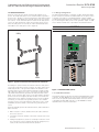
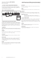
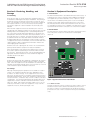
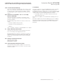
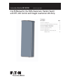
Instruction Booklet IB 70-8708 Effective August 2009 O & M Manual for the EGSU Automatic Transfer Switch with RTC-100 Control and Integral Loadcenter-100 Amp Contents Description Section Section Section Section Section Section Section Page 1: Introduction . . . . . . . . . . . . . . . . . . . . . 2 2: Receiving, Handling, and Storage . . . . 5 3: Equipment Description. . . . . . . . . . . . . 5 4. Installation and Wiring. . . . . . . . . . . . . 8 5. Functional Testing. . . . . . . . . . . . . . . . 13 6. Adjustments. . . . . . . . . . . . . . . . . . . . 14 7 Maintenance and Component Replacement . . . . . . . . . . . . . . . . . . . 15 Instruction Booklet IB 70-8708 O & M Manual for the EGSU Automatic Transfer Switch with RTC-100 Control and Integral Loadcenter-100 Amp Effective August 2009 Warning Section 1: Introduction READ AND UNDERSTAND THE INSTRUCTIONS CONTAINED HEREINAFTER BEFORE ATTEMPTING TO UNPACK, ASSEMBLE, OPERATE, OR MAINTAIN THIS EQUIPMENT HAZARDOUS VOLTAGES ARE PRESENT INSIDE TRANSFER SWITCH ENCLOSURES THAT CAN CAUSE DEATH OR SEVERE PERSONAL INJURY. FOLLOW PROPER INSTALLATION, OPERATION, AND MAINTENANCE PROCEDURES TO AVOID THESE VOLTAGES. THE TRANSFER SWITCH EQUIPMENT COVERED BY THIS INSTRUCTION BOOK IS DESIGNED AND TESTED TO OPERATE WITHIN ITS NAMEPLATE RATINGS. OPERATION OUTSIDE OF THESE RATINGS MAY CAUSE THE EQUIPMENT TO FAIL RESULTING IN DEATH, SERIOUS BODILY INJURY, AND/OR PROPERTY DAMAGE. ALL RESPONSIBLE PERSONNEL SHOULD LOCATE THE DOOR MOUNTED EQUIPMENT NAMEPLATE AND BE FAMILIAR WITH THE INFORMATION PROVIDED ON THE NAMEPLATE. A TYPICAL EQUIPMENT NAMEPLATE IS SHOWN IN FIGURE 1. L050412234 Cat No: EGSU100L24RAC Style No: GO No: ABC0123 Volts: 240 Poles: 2 Amps: 100 Phase: 1 ENCL TYPE: 3R ITEM: 001 PIECE: 001 OF: 001 Hertz: 60 Wire: 3 1.1 Preliminary Comments and Safety Precautions This technical document is intended to cover most aspects associated with the installation, application, operation, and maintenance of the Automatic Transfer Switch (ATS). It is provided as a guide for authorized and qualified personnel only. Please refer to the specific WARNING and CAUTION in Section 1.1.2 before proceeding. If further information is required by the purchaser regarding a particular installation, application, or maintenance activity, please contact an authorized Eaton sales representative or the installing contractor. 1.1.1 Warranty and Liability Information No warranties, expressed or implied, including warranties of fitness for a particular purpose of merchantability, or warranties arising from course of dealing or usage of trade, are made regarding the information, recommendations, and descriptions contained herein. In no event will Eaton be responsible to the purchaser or user in contract, in tort (including negligence), strict liability, or otherwise for any special, indirect, incidental or consequential damage, or loss whatsoever, including but not limited to damage or loss of use of equipment, plant or power system, cost of capital, loss of power, additional expenses in the use of existing power facilities, or claims against the purchaser or user by its customers resulting from the use of the information and descriptions contained herein. 1.1.2 Safety Precautions All safety codes, standards, and/or regulations must be strictly observed in the installation, application, operation, and maintenance of this device. 30-43465 warning Figure 1. Typical Automatic Transfer Switch Equipment Nameplate. All possible contingencies that may arise during installation, operation, or maintenance, and all details and variations of this equipment do not purport to be covered by these instructions. If further information is required by the purchaser regarding a particular installation, application, or maintenance activity, please contact an authorized Eaton sales representative or the installing contractor. THE WARNINGS AND CAUTIONS INCLUDED AS PART OF THE PROCEDURAL STEPS IN THIS DOCUMENT ARE FOR PERSONAL SAFETY AND PROTECTION OF EQUIPMENT FROM DAMAGE. AN EXAMPLE OF A TYPICAL WARNING LABEL HEADING IS SHOWN ABOVE TO FAMILIARIZE PERSONNEL WITH THE STYLE OF PRESENTATION. THIS WILL HELP TO ENSURE THAT PERSONNEL ARE ALERT TO WARNINGS, WHICH APPEAR THROUGHOUT THE DOCUMENT. IN ADDITION, CAUTIONS ARE ALL UPPER CASE AND BOLDFACE. CAUTION READ AND UNDERSTAND THE MATERIAL PRESENTED IN THIS DOCUMENT BEFORE ATTEMPTING INSTALLATION, APPLICATION, OPERATION, OR MAINTENANCE OF THE EQUIPMENT. IN ADDITION, ONLY QUALIFIED PERSONS SHOULD BE PERMITTED TO PERFORM ANY WORK ASSOCIATED WITH THE EQUIPMENT. ANY WIRING INSTRUCTIONS PRESENTED IN THIS DOCUMENT MUST BE FOLLOWED PRECISELY. FAILURE TO DO SO COULD CAUSE PERMANENT EQUIPMENT DAMAGE. 2 eaton corporation www.eaton.com O & M Manual for the EGSU Automatic Transfer Switch with RTC-100 Control and Integral Loadcenter-100 Amp Instruction Booklet IB 70-8708 Effective August 2009 1.2 General Information 1.2.1 Design Configuration ATSs are used to protect critical electrical loads against loss of power. The load’s utility power source is backed up by a generator power source. An ATS is connected to both the utility and generator power sources and supplies the load with power from one of these two sources. In the event that power is lost from the utility power source, the ATS transfers the load to the generator power source. Once the utility power is restored, the load is automatically transferred back to the utility power source (Figure 2). The Eaton Residential ATS is a rugged, compact design that utilizes power contactors to transfer essential loads from one power source to another (see Figure 3). The Residential ATS contains suitable mechanical and electrical interlock switches to eliminate the possibility of connecting the utility service to the generator output. In addition, a manual override lever is provided for the transfer function Generator warning Do not manually transfer THE switch while under load. Utility Load Figure 2. Typical Load Transfer Switch (Contactor) Schematic. An intelligence system initiates the transfer when the utility power source fails or falls below a preset voltage. An engine start is then initiated by the ATS or the generator and the ATS transfers to the generator power source when sufficient generator voltage is available. When the utility power source is restored, the ATS automatically transfers back and the generator will shut down after a time delay. In the event the utility power source fails and the generator power source does not appear, the ATS remains connected to the utility power source until the generator power source does appear. Conversely, if connected to the generator power source and the generator power source fails while the utility power source is still unavailable, the ATS remains connected to the generator power source. Figure 3. EGSU100L24RAC (100 A). 1.2.2 Load Shed Contacts This transfer switch incorporates the Eaton RTC-100 transfer switch controller. The RTC-100 has two sets of active load shed contacts. There is also an optional load shed board that connects to and is controlled by the RTC-100 controller. See IB 70-8698 for further explanation and connection information. ATSs automatically perform the transfer function, and include three basic elements. 1. Main contacts to connect and disconnect the load to and from the source of power. 2. Solenoids to make the transfer of the main contacts from source to source. 3. Intelligence/supervisory circuits to constantly monitor the condition of the power sources and thus provide the intelligence necessary for the switch and related circuit operation. eaton corporation www.eaton.com 3 Instruction Booklet IB 70-8708 O & M Manual for the EGSU Automatic Transfer Switch with RTC-100 Control and Integral Loadcenter-100 Amp Effective August 2009 1.3 Transfer Switch Catalog Number Identification Re-Transfer ATS equipment catalog numbers provide a significant amount of relevant information pertaining to a specific piece of equipment. The Catalog Number Identification Table (see Table 1) provides the required interpretation information. Re-transfer is defined as a change of the load connection from the Generator to the Utility. Utility is the primary source (normal source, normal power source, or normal). Table 1. ATS Catalog Numbering System. E Manufacturer Eaton GSU Type Generator Switch Universal 100 Ampere Rating 100-100A L24 R Loadcenter L24 - 24 Circuit Generator AC Enclosure Type Generator is the secondary source (generator emergency source, emergency power source, emergency, standby, or backup source). R = Type 3R Utility: Failed or Fails 1.4 Environmental and Operational Conditions Normally, an ATS is applied indoors in an electrical equipment room. It can also be used for normal outdoor applications (with standard NEMA 3R enclosure) where the equipment is subject to falling rain, freezing temperatures, and 95% humidity (non-condensing). The ambient temperature range for operation is between -20 and 70°C (-4 and 158°F). 1.5 Glossary With respect to their use within this document and as they relate to transfer switch and controller operation, the following terminology is defined. Available A source is defined as “available” when it is within its undervoltage setpoint ranges for the nominal voltage setting. Connected Connected is defined as when the input is shorted by an external contact or connection. Failed or Fails A source is defined as “failed” when it is outside of the applicable voltage setpoint ranges for the nominal voltage and for a time exceeding 0.5 seconds after the time delay emergency fail (TDEF) time delays expires. Failsafe Failsafe is a feature that prevents disconnection from the only available power source and also forces a transfer or re-transfer operation to the only available power source. eaton corporation www.eaton.com Utility is defined as “failed” when it is outside of its undervoltage setpoint ranges for the nominal voltage and frequency setting. Load Shed AC-Active Load Control Blank-Passive Load Shed 4 Utility Generator: Failed or Fails Generator is defined as “failed” when it is outside of its undervoltage/underfrequency/overfrequency (if applicable) setpoint ranges for the nominal voltage and frequency setting for a time exceeding 0.5 seconds after the Time Delay Emergency Fail (TDEF) time delay expires. Transfer Transfer is defined as a change of the load connection from the Utility to the Generator power source. Unconnected Unconnected is defined as when the input is not shorted by an external contact or connection. Instruction Booklet IB 70-8708 O & M Manual for the EGSU Automatic Transfer Switch with RTC-100 Control and Integral Loadcenter-100 Amp Effective August 2009 Section 2: Receiving, Handling, and Storage Section 3: Equipment Description 2.1 Receiving The Eaton Residential ATS is assembled and tested at the factory. It is designed to be used in conjunction with standby power distribution equipment to provide an alternate source of power to critical circuits in the event that the primary power source is interrupted. Every effort is made to ensure that the ATS equipment arrives at its destination undamaged and ready for installation. The packing is designed to protect the internal components as well as the enclosure. Care should be exercised, however, to protect the equipment from impact at all times. Do not remove the protective packaging until the equipment is at the installation site and ready to be installed. When the ATS equipment reaches its destination, the customer should inspect the shipping container for any obvious signs of rough handling and/or external damage that occurred during transportation. Record any external and internal damage for reporting to the transportation carrier and to the Eaton sales representative, once a thorough inspection is complete. All claims should be as specific as possible and include the Shop Order and General Order numbers. 3.1 Introduction This ATS monitors both utility and generator power sources and automatically transfers critical load circuits between the two sources, depending on which source is available. The utility power source is preferred and will remain connected to the switch if it is available. 3.2 Power Panel The power panel is used for making load, power, and neutral connections. The power contactor is mounted on a steel baseplate (Figure 4). A shipping label affixed to the shipping container includes a variety of equipment and customer information, such as General Order and catalog numbers. Make certain that this information matches the other shipping paper information. Each ATS enclosure is packaged in its own box. Do not discard the packing material until the equipment is ready for installation. Once the packaging is removed from the shipment, the enclosure door can be opened. A plastic bag of documents will be found in the enclosure. Important documents, such as wiring diagrams and appropriate instruction leaflets are enclosed within the bag and should be filed in a safe place. 2.2 Handling As previously mentioned, ATS equipment is packaged in its own box. Protect the equipment from impact at all times and do not double stack. Once the equipment is at the installation site and ready to be installed, the packaging material can be removed. Refer to Section 4 of this manual for specific installation instructions. 2.3 Storage Although well packaged, this equipment is not suitable for outdoor storage. The equipment warranty will not be applicable if there is evidence of outdoor storage. If the equipment is to be stored indoors for any period of time, it should be stored with its protective packaging material in place. Protect the equipment at all times from excessive moisture, construction dirt, corrosive conditions, and other contaminants. It is strongly suggested that the package-protected equipment be stored in a climate-controlled environment of -20 to 70°C (-4 to 158°F), with a relative humidity of 80% or less. Do not, under any circumstance, stack other equipment on top of an ATS equipment enclosure, whether packaged or not. Figure 4. Typical Power Panel for 100 A Model. 3.2.1 Main Contacts This ATS incorporates a power contactor. The main contacts connect and disconnect the load to and from the different power sources. The power contactor is mechanically and electrically interlocked to prevent the two sets of main contacts from being closed simultaneously. eaton corporation www.eaton.com 5 Instruction Booklet IB 70-8708 Effective August 2009 O & M Manual for the EGSU Automatic Transfer Switch with RTC-100 Control and Integral Loadcenter-100 Amp 3.3 RTC-100 Logic Panel 3. Time Delay Emergency to Normal (TDEN) The RTC-100 is a microprocessor-based transfer switch logic control package. The hardware and software of the controller contain the intelligence/supervisory circuits that constantly monitor the condition of the power sources. They provide the intelligence necessary for the operation of the ATS (Figure 5). This feature provides a time delay of the re-transfer operation to permit stabilization of Utility. Timing begins when the Utility becomes available. If the Generator fails during timing, then re-transfer is delayed for up to 6 seconds to allow the generator to recover. Fixed at 10 Seconds. 4. Time Delay for Engine Cool-down (TDEC) - EGSU Only This feature provides a time delay of the signal to initiate the engine/generator stop cycle after the re-transfer operation. This allows the engine/generator to cool down by running unloaded. Timing begins on completion of the re-transfer operation. Fixed setting of five minutes. Figure 5. RTC-100 Logic Control Panel. The RTC-100 controller has an operating temperature of -20 to 70°C (-4 to 158°F). 5. Generator Monitoring and Protection This feature provides monitoring and protection based on the Generator voltage setpoints. All feature functions are Failsafe operations. 5J. All Phase Undervoltage Protection Undervoltage: Dropout: 70% of nominal Pickup: 80% of nominal 7. Time Delay for Emergency Fail (TDEF) This feature provides a time delay that prevents a connected emergency source from being declared “failed” in order to override momentary generator fluctuations. If the generator power source remains in the failed state then, 0.5 seconds after the TDEF timer expires, the transfer switch will proceed with the programmed sequence for re-transfer. The controller circuit boards are protected by an insulating conformal coating. The specifications, under normal operating conditions, are as follows: • Fixed setting of six seconds Tolerance for voltage sensing function: ±1% of full scale. 3.4 EGSU ATS Features A variety of standard and optional features are available for Eaton ATSs. All features or combinations of features may not be available on specific ATSs. All features and/or accessories are Underwriters Laboratories (UL) listed unless noted. 12. Power Source Annunciation This feature provides LEDs to give power source availability indications. Switch Position Provides LEDs to indicate the switch position 3.4.1 Standard Features 12C. Utility - Connected - EGSU Only The following is a list of the standard features for the RTC Controlled ATS. 1. Time Delay Normal to Emergency (TDNE) 12D. Generator - Connected - EGSU Only This feature provides a time delay when transferring from the Utility to the Generator power source. Timing begins when the Generator becomes available. It permits controlled transfer of the load circuit to the Generator. Jumper selectable at 20 seconds or 50 seconds. Default is 20 seconds. 2. Time Delay on Engine Starting (TDES) - EGSU only 12G. Utility - Available This feature provides a time delay of the signal to initiate the engine/generator start cycle in order to override momentary power outages or voltage fluctuations of the utility source. 12H. Generator - Available Fixed setting of six seconds 6 eaton corporation www.eaton.com This feature provides a white LED that when lit, indicates the utility is connected. This feature provides a yellow LED that when lit, indicates the generator is connected. Power Source Availability Provides LEDs to indicate if a power source is available. LEDs may be integral or separate from the controller. This feature provides a green LED that, when lit, indicates the Utility is available. This feature provides an red LED that, when lit, indicates the generator is available. Instruction Booklet IB 70-8708 O & M Manual for the EGSU Automatic Transfer Switch with RTC-100 Control and Integral Loadcenter-100 Amp Effective August 2009 15N. Load Shed (Active) EGSU Only 3.5 Standards Eaton ATS equipment, enclosed in NEMA 3R enclosures, are listed for application by UL. In addition, Eaton ATSs are listed in File E313744 by Underwriters Laboratories, Inc. under Standard UL 1008. This standard covers the requirements for ATSs intended for use in ordinary locations to provide lighting and power as follows: Two sets of contacts are available and can be used to control large connected loads on the generator (i.e. air conditioners, hot tubs, etc.). The contacts are rated for 250 Vac, 5 amps. See IB 70-8698 for further explanation and connection information. 23K. Generator Test Selectable – Off / 7 / 14 / 28 Day Interval - EGSU Only This feature provides for automatic test operation of the generator. Available test cycles are 7, 14, or 28 days with a 15-minute duration. Programmable jumpers allow for selection of three test cycles: • Generator Start/Run Only (No Load); • Generator Test with Load Transfer; or • Disabled a. In standby systems, in accordance with article 702 of the National Electrical Code. Eaton ATSs are available to meet NFPA 110 for standby power systems. Eaton ATS equipment are listed for application by CSA. In addition, Eaton ATSs are listed in the Legacy File LR96245 Master Contract 163545 by Canadian Standards Association under Standard 22.2 #178-1978 This is a “Failsafe” operation. See IB 70-8698 for more details. 26. Utility - Monitoring and Protection This feature provides Utility monitoring and protection functions. If the Utility power supply fails, then the RTC-100 will begin the sequence of operations necessary to transfer the load circuit to the Generator power supply. All Feature 26 monitoring and protection functions are Failsafe operations. 26P. All Phase Undervoltage Protection Adjustable Undervoltage Dropout: 70% of nominal Pickup: 80% of nominal 37A. Service Equipment Rated Transfer Switch This feature provides the label “Suitable for use as Service Equipment” and the features necessary to meet the requirements for the label. eaton corporation www.eaton.com 7 Instruction Booklet IB 70-8708 Effective August 2009 Section 4: Installation and Wiring 4.1 General Eaton ATSs are factory wired and tested. Installation requires solidly mounting the enclosed unit and connecting the power cables and the auxiliary sensing circuits. Physical mounting procedures and power cable connections are covered in this section. Once a transfer switch is properly installed and wired, it should be mechanically and electrically checked for proper installation and operation. The procedures for these initial mechanical and electrical checks are outlined in Section 5 of this manual. warning be certain that the deadfront is properly installed before the transfer switch equipment is put into service. the deadfront provides protection from dangerous voltages at the line and load terminals when the equipment is in operation. failure to do so could result in personal injury or death. 4.2 Mounting Location Choose a location that offers a flat, rigid mounting surface capable of supporting the weight of the enclosed ATS equipment (see Figure 6, 100 A. Protect the transfer switch at all times against excessive moisture, dust, dirt, lint, and corrosive vapors. Figure 6. Dimensions and Plan View of a Standard EGSU (in.) (100 A) Type 3R Enclosure. 8 eaton corporation www.eaton.com O & M Manual for the EGSU Automatic Transfer Switch with RTC-100 Control and Integral Loadcenter-100 Amp Instruction Booklet IB 70-8708 O & M Manual for the EGSU Automatic Transfer Switch with RTC-100 Control and Integral Loadcenter-100 Amp Check to ensure there are no pipes, wires, or other mounting haards in the immediate mounting area that could create a problem. Carefully remove all packing material from the ATS enclosure at the installation site. Even though an equipment inspection was performed when the equipment was received, make another careful inspection of the enclosure and the ATS mechanism as the packing material is removed and the enclosure readied for mounting. Be especially alert for distorted metal, loose wires, or damaged components. Effective August 2009 4.4 Power Cable Connection warning POWER CONDUCTORS MAY HAVE VOLTAGE PRESENT THAT CAN CAUSE SEVERE PERSONAL INJURY OR DEATH. DE-ENERGIZE ALL POWER OR CONTROL CIRCUIT CONDUCTORS TO BE CONNECTED TO THE ATS EQUIPMENT BEFORE BEGINNING TO WORK WITH THE CONDUCTORS AND/ OR TERMINATING THEM TO THE EQUIPMENT 4.3 Mounting Procedure CAUTION CAUTION EXTREME CARE SHOULD BE TAKEN TO PROTECT THE ATS FROM DRILL CHIPS, FILINGS, AND OTHER CONTAMINANTS WHEN MAKING THE CABLE ENTRY HOLES AND MOUNTING THE ENCLOSURE TO PREVENT COMPONENT DAMAGE OR A FUTURE MALFUNCTION. NOTICE The installation must fully comply with all applicable codes, standards, and regulations. With the enclosed ATS equipment unpacked and ready for mounting, proceed with the following steps. Step 1:Depress the padlockable catch at the bottom of the door and slide the door downward (see Figure 7). Open the door and remove the deadfront. TO HELP PREVENT COMPONENT DAMAGE OR FUTURE MALFUNCTIONS, USE EXTREME CARE TO KEEP CONTAMINANTS OUT OF THE ATS EQUIPMENT WHEN MAKING THE POWER CABLE CONNECTIONS. Test all power cables prior to connection to the unit to ensure that the conductors or cable insulation has not been damaged while being pulled into position. Power cables are to be connected to solderless, screw type lugs located on the automatic transfer switching devices. Verify that the lugs supplied will accommodate the power cables being used. Also verify that the cables comply with all local electrical codes. Standard ATS equipment, as supplied from the factory, will accommodate the wire sizes shown in Table 2. Table 2. Wire Sizes for ATSs. Transfer Switch Amp Rating Contactor Wire Size Range Number of Cables per Phase 100 #14 – 2/0 1 Carefully strip the insulation from the power cables to avoid nicking or ringing of the conductor strands. Prepare the stripped conductor termination end by cleaning it with a wire brush. If aluminum conductors are used, apply an appropriate joint compound to the clean conductor surface area. CAUTION IMPROPER POWER CABLE CONNECTIONS CAN CAUSE EXCESSIVE HEAT AND SUBSEQUENT EQUIPMENT FAILURE. NNote: Tighten the cable lugs to the torque identified on the label affixed to the unit. Step 1:Connect cables as follows (see Figure 8, and Table 2): Figure 7. Location of the Door Latch. Step 2: Utilize the 5-point hanging system to mount. NOTICE For control wiring (generator engine start wiring), the wires must be isolated from both the Utility and Generator power source cables. Step 3:Mount the switch to a rigid structure as close to the electrical loads as possible. • The utility power cables to the utility lugs; • The generator power cables to the generator lugs; • The customer load cables to the distribution panel; • The neutral cables to the neutral bar; and • The ground wires to the ground bar. Warning Failure to properly connect this transfer switch per NFPA 70, the national electric code, may result in product failure, fire, loss of property, loss of life, ETc. eaton corporation www.eaton.com 9 Instruction Booklet IB 70-8708 O & M Manual for the EGSU Automatic Transfer Switch with RTC-100 Control and Integral Loadcenter-100 Amp Effective August 2009 Utility Lugs Generator Lugs Utility Lugs Load Lugs Generator Lugs Load Lugs Utility Sensing Wire Connection Figure 9. Generator Utility Sensing Wires Connection. Figure 8. Cable Connection Locations (100 A). Step 2:If your generator requires utility power for engine start sensing then the generator utility sensing connections are located on the fuse block that is installed at the bottom of the power panel (see Figure 9). The utility sensing wires, required for proper generator operations, are connected at this point. See Section 4.7 for more detailed information on connecting the generator utility sensing wires. 10 eaton corporation www.eaton.com Step 3:If your generator is a two wire start type generator that requires a contact closure or open to provide the start signal then connect the 2 wires to the connector located on J7. J7 is a form C contact that can be utilized for either form of two wire start circuits. If a contact closure is required for engine start, connect the two wires to J7-1 and J7-2. If a contact open is required for engine start, connect the two wires to J7-2 and J7-3 (see Figure 13). Instruction Booklet IB 70-8708 O & M Manual for the EGSU Automatic Transfer Switch with RTC-100 Control and Integral Loadcenter-100 Amp Effective August 2009 4.5 Wiring WARNING POWER CONDUCTORS AND control wiring MAY HAVE VOLTAGE PRESENT THAT CAN CAUSE SEVERE PERSONAL INJURY OR DEATH. DE-ENERGIZE ALL POWER OR CONTROL CIRCUIT CONDUCTORS BEFORE BEGINNING TO PERFORM ANY WIRING ACTIVITY TO OR WITHIN THE ATS EQUIPMENT. CAUTION CHECK THE ATS EQUIPMENT NAMEPLATE FOR RATED VOLTAGE. IT SHOULD BE THE SAME AS THE UTILITY AND GENERATOR LINE VOLTAGES. OPERATING THE EQUIPMENT ON IMPROPER VOLTAGE CAN CAUSE EQUIPMENT DAMAGE. Utility (Source 1) Non-Critical Loads Watt-Hour Meter Utility Panel Generator (Source 2) Transfer Switch 4.6 Installation In a typical installation for critical loads (see Figure 10), the ATS (1) and the generator (2) are connected to the power supply. The ATS and emergency distribution panel (1) receive utility power from a dedicated breaker in the utility service panel (3). The ATS and emergency panel receive generator power from the generator (2). Power from the utility feeds the utility panel. Circuit Breaker (typically included in Genset) Critical Loads Emergency Distribution Panel Figure 11. Diagram of a Typical Installation (Critical Load Only). 4.7 Generator Utility Sensing Connection The generator utility sensing connections are located on the fuse block that is installed at the bottom of the power panel. The utility sensing wires, required for proper generator operation, are connected at this point. Figure 10. Typical Installation of a Residential ATS. The ATS (1) and generator (2) are connected to the power supply. The automatic transfer switch is located between the generator and the utility panel (3). When the utility power fails, the ATS will sense the failure, the generator will start , and when sufficient generator voltage is available, the ATS will switch all loads to the emergency panel. All emergency loads will receive power from the generator. A line breaker is required between the generator power source and the transfer switch (see Figure 11). When utility power returns, the ATS will switch all power back to the utility panel and the generator will shut down. NNote: Prior to making the generator utility sensing connection to the ATS, set the generator control selector switch to the OFF position to prevent an unwanted generator start. Control wiring, such as the generator utility sensing wires, must be run separately from the power cables. Use the proper wire size as listed by the generator set (Genset) manufacturer. This ATS is intended for use on generators with built in auto start features. These generators sense, and react to, utility power (see Figure 12). The EGSU type ATS may also be used with generators that require open type remote starting contacts. One set of normally open contacts and one set of normally closed contacts are supplied eaton corporation www.eaton.com 11 Instruction Booklet IB 70-8708 O & M Manual for the EGSU Automatic Transfer Switch with RTC-100 Control and Integral Loadcenter-100 Amp Effective August 2009 4.9 Protection For Catalog #EGSU100L24RAC Only When protected by one of the following circuit breakers rated not more than 150 amperes, this transfer switch is rated for use on a circuit capable of delivering not more than 25,000 RMS symmetrical amperes, 240 volts maximum, but not more than the interrupting capacity of the selected circuit breaker. BR CH BRHH BWH FDC CSR CSH ED4 HED6 HED4 Utility Sensing Connection Figure 12. Connection of the Generator Utility Sensing Wires. J7 J7-1 J7-2 J7-3 Figure 13. Dry Contacts for Two Wire Engine Start - EGSU Only. 4.8 Preliminary Checks After the ATS enclosure is installed and power cables are connected to the equipment, thoroughly inspect the unit to ensure that no tools were left inside and that the cabinet is free of debris. If necessary, use a vacuum cleaner to remove any and all construction or installation debris from the equipment. Read and understand all labels on the equipment. Review and understand the wiring diagrams supplied with the equipment. Note any optional accessories that may have been furnished with this unit and review their operation. Verify that the phase-to-phase line voltages of both the utility and generator power sources are the same and that they match the rated voltage as indicated on the ATS ratings label. CAUTION SEVERE EQUIPMENT DAMAGE CAN RESULT IF THE UNIT IS NOT APPLIED AT PROPER VOLTAGE. DO NOT ENERGIZE THE EQUIPMENT IF THE SUPPLY VOLTAGES DO NOT MATCH EQUIPMENT RATINGS LABEL. 12 Eaton/Cutler-Hammer eaton corporation www.eaton.com Siemens CED6 ED6 When protected by circuit breakers without adjustable short-time response only or by fuses this transfer switchis rated for use on a curcuit ccapable of delivering not more than 10,000 RMS symmetrical amperes at 240V AC. MANUFACTURER-ANY BREAKER-ANY TYPE-ANY AMPS MAX-PER NEC Instruction Booklet IB 70-8708 O & M Manual for the EGSU Automatic Transfer Switch with RTC-100 Control and Integral Loadcenter-100 Amp Section 5: Functional Testing WARNING YOU ARE READY TO ENERGIZE THE EQUIPMENT. VOLTAGES WITHIN THE ENCLOSURE ARE CAPABLE OF CAUSING SEVERE PERSONAL INJURY OR DEATH. USE EXTREME CAUTION TO AVOID CONTACT WITH ENERGIZED EQUIPMENT. Effective August 2009 Step 6: Close the utility breaker described in Step 1 of Section 5.2. Step 7: The ATS Time Delay Emergency (Generator) to Normal (Utility) (TDEN) timer will begin timing, and the solenoid will engage and automatically switch from the GENERATOR to the UTILITY position and the generator will shut down after a cool-down period. 5.4 Manual Operation 5.1 Preliminary Checks Step 1: Check all loads connected to the ATS to ensure that they are ready to be energized. 5.2 Energize the Switch Step 1:Close the upstream utility power source breaker or switch to connect the ATS to the utility power source voltage. Step 2:Using a voltmeter, measure the line-to-line and the line-to-neutral voltages across the utility line terminals to ensure the utility voltage is correct. Step 3:If the voltage is acceptable, the solenoid will engage and the contactor will automatically switch to the UTILITY position. WARNING CONTACT WITH ENERGIZED COMPONENTS WILL CAUSE ELECTRICAL SHOCK CAPABLE OF PRODUCING SEVERE PERSONAL INJURY OR DEATH. USE EXTREME CAUTION TO AVOID CONTACT WITH ENERGIZED COMPONENTS WHEN USING A METER FOR VOLTAGE CHECKS. Step 4: Position the generator control selector switch, located on the standby generator, to the AUTOSTART position. (It may also be labeled REMOTE START or AUTO.) 5.3 Operational Checks Step 1: Open the upstream utility breaker originally closed in Step 1 of Section 5.2. NOTICE This will simulate an interruption of the utility power source. Step 2: After a time delay the standby generator engine will start. Step 3: Using a voltmeter, measure the line-to-line and line-to-neutral voltages across the generator line terminals to ensure that the generator emergency voltage is correct. If necessary, make adjustments to the voltage regulator on the generator according to the manufacturer’s recommendations to correct any voltage deviations. The ATS will only respond to the correct voltage from the generator power source. warning DO NOT ATTEMPT TO MANUALLY OPERATE THE ATS WITH the utility OR generator AVAILABLE. warning HIGH VOLTAGES ARE PRESENT IN AND AROUND TRANSFER SWITCH EQUIPMENT. BEFORE ATTEMPTING TO MANUALLY TRANSFER, DISCONNECT THE LINE POWER FROM THE EQUIPMENT BEING SERVICED BY OPENING AND LOCKING OUT, IF POSSIBLE, THE NEXT HIGHEST DISCONNECT DEVICE. FAILURE TO FOLLOW THIS PROCEDURE COULD CAUSE SEVERE PERSONAL INJURY AND/OR DEATH. ALWAYS TURN THE utility POWER OFF AND TURN THE generator (IF A GENERATOR) CONTROL SELECTOR SWITCH TO THE “oFF” POSITION BEFORE ATTEMPTING A MANUAL TRANSFER. warning InsurE THE DEADFRONT IS INSTALLED PRIOR TO energizing the TRANSFER SWITCH. To Manually Operate Step 1: Disconnect all sources of power. Step 2: Disconnect the J9 connector from the RTC-100 controller. Step 3: Locate the manual lever between the solenoids (see Figure 14). Step 4: Locate the handle used to manually transfer the switch. Step 5: Attach the handle to the manual lever. Step 6: Move the lever to the left to go to Utility or to the right to connect to Generator. Step 7: Reconnect the power. Step 8: If automatic operation is required, disconnect all sources of power, reinstall the J9 connector, and reconnect the power. Step 4: Close the upstream generator power source breaker or switch to connect the ATS to the generator power supply source. Step 5: The ATS Time Delay Normal (Utility) to Emergency (Generator) (TDNE) will begin to time after the generator engine begins to run. After time out, the solenoid will engage and the contactor will automatically switch from the UTILITY to the GENERATOR position. eaton corporation www.eaton.com 13 Instruction Booklet IB 70-8708 Effective August 2009 O & M Manual for the EGSU Automatic Transfer Switch with RTC-100 Control and Integral Loadcenter-100 Amp Section 6: Adjustments 6.1 General Refer to IB 70-8698, supplied with the ATS for RTC-100 Controller adjustments and functions. Figure 14. ATS Manual Operating Handle in Use Shown Connected to Source 2. 14 eaton corporation www.eaton.com Instruction Booklet IB 70-8708 O & M Manual for the EGSU Automatic Transfer Switch with RTC-100 Control and Integral Loadcenter-100 Amp Section 7: Maintenance and Component Replacement 7.1 Introduction WARNING HIGH VOLTAGES ARE PRESENT IN AND AROUND TRANSFER SWITCH EQUIPMENT. BEFORE INSPECTING OR MAINTAINING THIS EQUIPMENT, DISCONNECT THE LINE POWER FROM THE EQUIPMENT BEING SERVICED BY OPENING AND LOCKING OUT, IF POSSIBLE, THE NEXT HIGHEST DISCONNECT DEVICE. FAILURE TO FOLLOW THIS PROCEDURE COULD CAUSE SEVERE PERSONAL INJURY AND/OR DEATH. Effective August 2009 In general, ATS equipment is designed to be relatively maintenance free under normal usage. However, because of the variability of application conditions and the importance placed on dependable operation by this type of equipment, inspection and maintenance checks should be made on a regularly scheduled basis. Since equipment maintenance will consist mainly of keeping the equipment clean, the frequency of maintenance will depend, to a large extent, on the cleanliness of its surroundings. If a significant amount of dust or foreign matter is present, a more frequent maintenance schedule should be followed. It is suggested that visual inspections of the equipment be made on a regular basis, not just during regularly scheduled periods. Always be alert for an accumulation of dirt in and around the structure, loose parts and/or hardware, cracks and/or discoloration to insulation, and damaged or discolored components. Figure 15 is the wiring diagram for the EGSU 100 Amp ATS switch. NNote: Only qualified and experienced personnel should attempt any diagnostic work using this diagram. Figure 15. Wire Diagram for the EGSU100L24RAC ATS (shown Deenergized). eaton corporation www.eaton.com 15 Instruction Booklet IB 70-8708 O & M Manual for the EGSU Automatic Transfer Switch with RTC-100 Control and Integral Loadcenter-100 Amp Effective August 2009 7.2 Procedures A suggested maintenance procedure to be followed is outlined in Table 3. Table 3. Recommended Periodic Maintenance Procedures Step Action a. Make the transfer switch equipment safe for inspection and/or maintenance. Disconnect the line power from the equipment being serviced by opening next highest disconnect device. Make certain that any accessory control power is switched off. b. Inspect the structure area for safety hazards or potential maintenance problems. Inspect the area, especially where the contactor is installed, for any safety hazards, including personal safety and fire hazards. Exposure to certain chemical vapors can cause deterioration of the electrical connections. Inspect for accumulated dirt, loose hardware, or physical damage. Examine the primary insulation for evidence of cracking or overheating. Overheating will show as discoloration, melting, or blistering of the conductor insulation, or as pitting or melting of the conductor surfaces due to arcing. Inspect the secondary control connections for damage, and control wiring for insulation integrity. c. Inspect the contactor for dust, dirt, soot, grease, moisture, or corrosion. Remove dust, dirt, soot, grease, moisture, and corrosion contamination from the surface of the switching device using a dry, soft lint-free cloth, dry soft bristle brush, and vacuum cleaner. Do not blow debris into the contactor. If contamination is found, look for the source and fix the problem. d. Check for material integrity, uneven wear, discoloration, or loose hardware. Severe material cracking will require replacement and loose hardware will need to be tightened. e. Check the terminals and connectors for looseness or signs of overheating. Overheating will show as discoloration, melting, or blistering of the conductor insulation. Connections that do not have signs of looseness or overheating should not be disturbed. f. Exercise the contactor if it is not often exercised while in operation. This will permit the wiping action by the contacts. If a switching device is used for frequent switching during normal operation, this step can be disregarded. g. Return the transfer switch equipment to service. Make certain all barriers are in place and the door is closed. Re-apply generator and utility power. 16 eaton corporation www.eaton.com O & M Manual for the EGSU Automatic Transfer Switch with RTC-100 Control and Integral Loadcenter-100 Amp Instruction Booklet IB 70-8708 Effective August 2009 7.3 Maintenance Log Date Action Example: 01/01/09 Inspected and cleaned. eaton corporation www.eaton.com 17 Instruction Booklet IB 70-8708 O & M Manual for the EGSU Automatic Transfer Switch with RTC-100 Control and Integral Loadcenter-100 Amp Effective August 2009 7.4 Component Replacement 7.4.1 Component Replacement Instructions Certain components within the ATS are field replaceable. Table 4 lists the part numbers to use when ordering replacement components. To order replacement components, contact an authorized Eaton Sales Representative. 7.4.1.1 100 Ampere RTC-100 Controller Table 4. Field Replaceable Components. Component Part Number ATS Model Contactor 99-5638 100 A RTC-100 Controller RTC100 100 A Harness EGSU 99-5638-12 100 A Service Entrance Breaker 99-5638-4 100 A Ground Bar 99-5638-15 100 A Lugs - Contactor 99-5638-6 100 A Neutral Bar 99-5638-17 100 A SurgTel DHW4PT 100 A SurgCable DCXCAB2 100 A TVSS CHSPULTRA 100 A WARNING HIGH VOLTAGES ARE PRESENT IN AND AROUND TRANSFER SWITCH EQUIPMENT. BEFORE ATTEMPTING TO REPLACE ANY COMPONENT, DISCONNECT THE LINE POWER FROM THE EQUIPMENT BEING SERVICED BY OPENING AND LOCKING OUT, IF POSSIBLE, THE NEXT HIGHEST DISCONNECT DEVICE. FAILURE TO FOLLOW THIS PROCEDURE COULD CAUSE SEVERE PERSONAL INJURY AND/OR DEATH. ALWAYS TURN THE UTILITY (SOURCE 1) POWER OFF AND TURN THE GENERATOR (SOURCE 2) CONTROL SELECTOR SWITCH TO THE “OFF” POSITION BEFORE ATTEMPTING TO REPLACE ANY COMPONENTS. NOTICE Apply utility (source 1) power and place the generator control selector switch in the “AUTO” position after the component has been replaced. Test the system for proper functionality. 18 eaton corporation www.eaton.com Figure 16. Controller Board Installed in a EGSU ATS. Instruction Booklet IB 70-8708 O & M Manual for the EGSU Automatic Transfer Switch with RTC-100 Control and Integral Loadcenter-100 Amp Step 1: Turn the Generator Start select to “OFF” before attempting to replace the RTD-100 Controller. Ensure all sources of power are removed. Effective August 2009 7.4.1.2 100 A Neutral Bar Step 2: Disconnect the plugs from the controller (see Figure 17). Step 3: Disconnect the wires connected to J8. Step 4: Remove the four (4) screws located at the corners of the controller that secure it to the power panel. Remove the controller (see Figure 17). Mounting Screws J2 Neutral Bars J9 Figure 18. 100 A Neutral Bar. Step 1: Turn the utility (Source 1) power off and turn the generator (Source 2) control selector switch to the “OFF” position before attempting to replace the neutral bar. J1 Step 2: Disconnect all wire cables from the neutral bar. J8 Step 3: Remove the two screws in the black base using a blade screwdriver or 0.375 in. socket or nut driver. Remove the strap with a common straight blade screw driver and then remove the neutral bar. J7 J3 J6 J5 Figure 17. Removing the Controller Board. Screws Step 5: Align the new controller with the mounting holes. Secure the new controller board using the existing hardware. Tighten the screws. Step 6: Connect all the plugs to their original receptacles. Step 7: Reconnect the wires to J8. Step 8: Reapply power to the transfer switch. Figure 19. Replacing the 100 A Neutral Bar. Step 9: Place the generator control selector switch in the “AUTO” position after the controller has been replaced. (The generator may start but will shut down within five minutes.) Test the system for proper functionality. Step 4: Mount the neutral bar to the base plate using the hardware supplied. Step 5: Reattach the strap to the new neutral bar. Step 6: Reconnect all wire cables to the neutral bar. Step 7: Apply utility (Source 1) power and place the generator control selector switch in the “AUTO” position after the neutral bar has been replaced. Test the system for proper functionality. eaton corporation www.eaton.com 19 Instruction Booklet IB 70-8708 Effective August 2009 O & M Manual for the EGSU Automatic Transfer Switch with RTC-100 Control and Integral Loadcenter-100 Amp 7.4.1.3 Ground Bart 7.4.1.4 Replacing the Contactor N1 E1 N2 E2 Utility Aux. Switch Utility Coil Mounting Screws Ground Bar Figure 20. Replacing the Ground Bar. Step 1: Turn the utility (Source 1) power off and turn the generator (Source 2) control selector switch to the “OFF” position before attempting to replace the ground bar Step 2: Disconnect all wire cables from the ground bar. Step 3: Remove the screws securing the ground lug using a blade screwdriver (see Figure 20). Remove the ground bar. Step 4: Secure the new ground bar to the base plate using the hardware supplied. Step 5: Reconnect all wire cables to the ground bar. Step 6: Apply utility (Source 1) power and place the generator control selector switch in the “AUTO” position after the ground bar has been replaced. Test the system for proper functionality. Generator Aux. Switch Generator Coil Figure 21. Replacing the Contactor. Step 1: Turn the utility (Source 1) power off and turn the generator (Source 2) control selector switch to the “OFF” position before attempting to replace the contactor. Step 2: Note their location then disconnect the twelve (12) red wires from the contactor (see Figure 21). NNote: All wires connected to the contactor are labeled to ease identification. Step 3: Remove the three (3) screws securing the contactor to the base plate using a blade screwdriver or 0.25 in. socket or nut driver. Remove the contactor. Step 4: Following the replacement steps for the 100 A lugs (see Sections 7.4.1.6), remove the lugs from the old contactor then install the lugs on the new contactor. Step 5: Secure the contactor onto the base plate using the hardware supplied. Step 6: Reattach the twelve (12) red wires to the contactor. Examine each wire to find the name then refer to Figure 21 for the correct connection point. Step 7: Reconnect all wire cables to the contactor as per their original connections. Step 8: Apply utility (Source 1) power and place the generator control selector switch in the “AUTO” position after the contactor has been replaced. Test the system for proper functionality. 20 eaton corporation www.eaton.com O & M Manual for the EGSU Automatic Transfer Switch with RTC-100 Control and Integral Loadcenter-100 Amp Instruction Booklet IB 70-8708 Effective August 2009 Step 3: Disconnect the plugs from the controller (see Figure 17). Remove screw securing the fuse block. 7.4.1.5 Wiring Harness The wire harness is now free to be removed. Step 4: Place the new wiring harness in the ATS. Step 5: Connect the plugs to the controller. Step 6: Reattach the red wires to the contactor. Examine each wire to find the name then refer to Figure 23 for the correct connection point. Step 7: Apply utility (Source 1) power and place the generator control selector switch in the “AUTO” position after the wiring harness has been replaced. Test the system for proper functionality. 7.4.1.6 Replacing the 100 A Lugs Utility Lugs Figure 22. Wiring Harness Installed in a EGSU ATS. Step 1: Turn the utility (Source 1) power off and turn the generator (Source 2) control selector switch to the “OFF” position before attempting to replace the wiring harness. Step 2: Note their location then disconnect the red wires from the contactor. Generator Lugs NNote: All wires connected to the contactor are labeled to ease identification. Load Lugs Figure 24. Replacing the 100 A Lugs. Step 1: Turn the utility (Source 1) power off and turn the generator (Source 2) control selector switch to the “OFF” position before attempting to replace the lugs. Step 2: Disconnect all wire cables from the contactor. Step 3: Note their location then disconnect the red wires from the contactor (see Figure 21). NNote: All wires connected to the contactor are labeled to ease identification. Utility Coil. Connections Utility Aux. Com Utility Aux. N.C. Gen Aux. N.C. Gen Aux. Com. Gen Coil. Connections Figure 23. Wires to Disconnect from the Contactor. eaton corporation www.eaton.com 21 Instruction Booklet IB 70-8708 O & M Manual for the EGSU Automatic Transfer Switch with RTC-100 Control and Integral Loadcenter-100 Amp Effective August 2009 For All ATSs Step 4: Remove the four (4) screws securing the contactor to the base plate using a blade screwdriver or 0.25 in. socket or nut driver. Step 5: Remove the two (2) generator lugs and the two (2) load lugs using a blade screwdriver (see Figure 24). Step 6: Once the load lugs have been removed, insert a blade screwdriver up through the circular hole in the load lug bus and remove screws securing the two (2) generator lugs. Step 7:Place the new utility lugs on the utility bus so the anti-turn protrusions fit in the holes. Once the lugs are in place, take one (1) supplied control wire terminal and hold it underneath the bus. Using one (1) screw and one (1) washer supplied, tighten the control wire terminal and lug to the utility bus. Repeat the process of the second utility lug. Ensure that no gaps are present between the lugs and bus. Step 8:Place the new generator lugs on the generator bus. Once the lugs are in place, take one (1) supplied control wire terminal and hold it underneath the bus. Using one (1) screw and one (1) washer supplied, tighten the control wire terminal and lug to the generator bus. Repeat the process of the second generator lug. Ensure that no gaps are present between the lugs and bus. Step 9: Secure the load lugs to the load bus using the hardware supplied. NNote: The load lugs do not require control wire terminals. Step 10:Secure the contactor to the base plate using the four (4) screws supplied. Step 11:Reattach the red wires to the contactor. Examine each wire to find the name then refer to Figure 28 for the correct connection point. Step 12:Reconnect all cables to the contactor as per their original connections. Step 13:Apply utility (Source 1) power and place the generator control selector switch in the “AUTO” position after the lugs have been replaced. Test the system for proper functionality. 7.5 Troubleshooting Table 5 contains troubleshooting information for the EGSU ATS. If a problem still exists after completing the troubleshooting procedures, contact an authorized Eaton sales representative. Table 5. Troubleshooting Chart. Problem Cause Correction The automatic transfer switch does not transfer to the generator. 1 The generator breaker is open. 2. The generator voltage is not acceptable. 1. Reset the generator circuit breaker. 2. Refer to the generator User’s Manual The automatic transfer switch does not transfer to the utility. 1. The service disconnect breaker is open. 2. The utility voltage is not acceptable. 1. Reset the service disconnect breaker. 2. Wait for the utility voltage to return to normal The generator is still running after the transfer switch transfers to the utility. Engine cool down period. The engine should stop after the cool down. 22 eaton corporation www.eaton.com O & M Manual for the EGSU Automatic Transfer Switch with RTC-100 Control and Integral Loadcenter-100 Amp Instruction Booklet IB 70-8708 Effective August 2009 Notes: eaton corporation www.eaton.com 23 Instruction Booklet IB 70-8708 Effective August 2009 O & M Manual for the EGSU Automatic Transfer Switch with RTC-100 Control and Integral Loadcenter-100 Amp This instructional literature is published solely for information purposes and should not be considered all-inclusive. If further information is required, you should consult an authorized Eaton sales representative. The sale of the product shown in this literature is subject to the terms and conditions outlined in appropriate Eaton selling policies or other contractual agreement between the parties. This literature is not intended to and does not enlarge or add to any such contract. The sole source governing the rights and remedies of any purchaser of this equipment is the contract between the purchaser and Eaton. NO WARRANTIES, EXPRESSED OR IMPLIED, INCLUDING WARRANTIES OF FITNESS FOR A PARTICULAR PURPOSE OR MERCHANTABILITY, OR WARRANTIES ARISING FROM COURSE OF DEALING OR USAGE OF TRADE, ARE MADE REGARDING THE INFORMATION, RECOMMENDATIONS, AND DESCRIPTIONS CONTAINED HEREIN. In no event will Eaton be responsible to the purchaser or user in contract, in tort (including negligence), strict liability or otherwise for any special, indirect, incidental or consequential damage or loss whatsoever, including but not limited to damage or loss of use of equipment, plant or power system, cost of capital, loss of power, additional expenses in the use of existing power facilities, or claims against the purchaser or user by its customers resulting from the use of the information, recommendations and description contained herein. Eaton Corporation Electrical Group 1000 Cherrington Parkway Moon Township, PA 15108 United States 877-ETN-CARE (877-386-2273) Eaton.com © 2009 Eaton Corporation All Rights Reserved Printed in USA Publication No. IB 70-8708 / TBG000249 August 2009 PowerChain Management is a registered trademark of Eaton Corporation. All other trademarks are property of their respective owners.