1
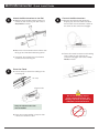
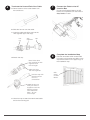
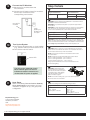
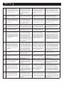
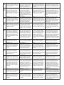
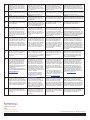
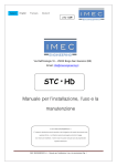
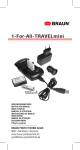
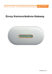
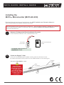
® M 2 1 5 Q U I C K I N S TA L L G U I D E Installing the M215TM Microinverter (M215-60-230) Read and follow all warnings and instructions in the M215 Installation and Operation Manual at http://www.enphase.com before using this document. The microinverters will not produce power until the EnvoyTM Communications Gateway is installed and configured with an appropriate grid profile. For instructions, refer to the Envoy Installation and Operation Manual at http://www.enphase.com. 1 Measure AC Voltage at the Electricity Network Connection Check all phase conductors: line to neutral and line to line. volt meter set to ACV Electrical distribution board Acceptable ranges are shown in Step Details on back. 2 Position the Engage™ Cable a. Lay out the cabling along the installed mounting rail for the AC branch circuit. b. Install an AC branch circuit junction box at a suitable location on the mounting rail. Engage Cable See notes in Step Details on back. Check the drop connector labels to be sure that you have the right cable. You must use 3G2.5 cable for single-phase or 5G2.5 cable for three-phase. drop connector M215 Microinverter 3 Quick Install Guide Attach the Microinverters to the Rail a. Mark the approximate centers of each PV module on the mounting rail. See notes in Step Details on back. b. Mount the microinverters with the silver side facing up and the black side facing down. c. If required, bond (earth) the microinverter chassis to the mounting rail. 4 5 Connect the Microinverters a. Remove and discard the temporary shipping cap from the cable connector and connect the microinverter. Listen for two clicks as the connectors engage. b. Cover all unused connectors with sealing caps. Listen for two clicks as the connectors engage. See notes in Step Details on back. Dress the Cable a.Use tie wraps to attach the cabling to the mounting rail. tie wrap release holes Do not use shipping caps to cover unused connectors. The shipping cap does not provide an adequate environmental seal. Keep the release holes clear and accessible. b. Dress any excess cabling in loops so that it does not contact the roof. 6 Terminate the Unused End of the Cable a. Remove 60mm of the cable sheath from the conductors. 7 Connect the Cable to the AC Junction Box Connect the Engage Cable to the AC branch circuit junction box. See notes in Step Details on back. b. Slide the hex nut onto the cable. c. Insert the cable end all the way into the wire organiser (up to the stop). hex nut wire organiser cap 8 d. Attach the cap. bend wires down into recesses of wire organiser and trim to length Complete the Installation Map Peel the removable serial number label from each microinverter and affix it to the respective location on the paper copy of the installation map. place cap over the wire organiser hold the cap with the disconnect tool or a screwdriver rotate the hex nut with your hand or a spanner until the latching mechanism meets the base – do not over-torque e. Use a tie wrap to attach the terminated cable end to the mounting rail. affix serial number labels 9 Connect the PV Modules a. Mount the PV modules above the microinverters. b.Connect the DC leads of each PV module to the DC input connectors of the corresponding microinverter. Step Details 1 Single-Phase Service Three Phase Service L1 to N L1 to L2 to L3 360 to 440 Vac L1, L2, L3 to N 207 to 253 Vac 207 to 253 Vac 2 WARNING: Perform all electrical installations in accordance with all applicable local electrical standards. 60-cell PV module verify polarity on at least one unit pair 10 WARNING: Only use electrical system components approved for wet locations. WARNING: Do NOT exceed the maximum number of microinverters in an AC branch circuit as listed in the table below. Each branch circuit must be protected with a 20A maximum breaker. Service type Max M215s per branch Single-Phase Service 17 Three-Phase Service 27 WARNING: Size the AC cable/wire size to account for voltage drop. Select conductor diameter based on the distance from the beginning of the microinverter AC branch circuit to the breaker in the AC mains. See Voltage Drop Calculations at http://www.enphase.com. Turn Up the System a. Turn ON the AC disconnect or circuit breaker (e.g., isolation switch) for each branch circuit. b.Turn ON the main AC switch. 3 WARNING: Allow a minimum of 1.9cm between the roof and the bottom of the microinverter. Also allow 1.3cm between the back of the PV module and the top of the microinverter. NOTE: The AC output neutral is not bonded to earth inside the microinverter. status LED The LED on the underside of each M215 will blink green six times to indicate successful connection two minutes after DC power is applied. NOTE: Torque the microinverter fasteners to these values: • 6mm mounting hardware – 5 N m minimum • 8mm mounting hardware – 9 N m minimum • 10/32 earthing cleat screw – 2 N m minimum Using a power screwdriver is not recommended due to the risk of thread galling. 5 Disconnect tool WARNING: Install sealing caps on all unused AC connectors as they become live when the system is energised. IP67-rated sealing caps are required to protect against moisture ingress. NOTE: To remove a sealing cap, you must use the Enphase disconnect tool or a screwdriver. 11 Next Steps Refer to the Envoy Communications Gateway Quick Install Guide for information on Envoy installation, Enlighten set up, and grid profile configuration. Enphase Energy, Inc. 1420 N. McDowell Blvd. Petaluma, CA 94954 USA [email protected] http://www.enphase.com © 2012 Enphase Energy Inc. All rights reserved. 7 NOTE: The cabling uses the following wiring scheme. Single-Phase Service Three-Phase Service Brown – L1 Blue – Neutral Green/yellow – Ground Brown – L1 Black – L2 Gray – L3 Blue – Neutral Green/yellow – Ground M215 ⚠ ® M215TM (M215-60-230) Important Safety Information This document contains important instructions for use during installation and maintenance of the Enphase M215™ Microinverter. To reduce the risk of electrical shock, and to ensure the safe installation and operation of the Enphase Microinverter, the following safety symbols appear throughout this document to indicate dangerous conditions and important safety instructions. Informations importantes sur la sécurité Ce manuel contient des instructions importantes à respecter pendant l’installation et la maintenance du micro-onduleur Enphase M215™. Pour réduire les risques d’électrocution et garantir une installation et un fonctionnement en toute sécurité du micro-onduleur Enphase, ce document utilise les symboles de sécurité suivants ; ils informent des conditions dangereuses et donnent des instructions importantes relatives à la sécurité. Importanti informazioni di sicurezza Questo manuale contiene importanti istruzioni da seguire nel corso dell’installazione e della manutenzione del microinverter Enphase M215™. Per ridurre il rischio di folgorazione e garantire la sicurezza di installazione e funzionamento del microinverter Enphase, nel presente documento vengono raffigurati i seguenti simboli di sicurezza indicanti condizioni di pericolo e istruzioni di sicurezza importanti. Wichtige Sicherheitsinformationen Dieses Dokument enthält wichtige Anleitungen zur Installation und Wartung des Enphase M215™ Mikrowechselrichters. Um das Risiko eines Stromschlags zu reduzieren und eine sichere Installation und Bedienung des Enphase Mikrowechselrichters zu gewährleisten, wird in diesem Dokument mit den folgenden Sicherheitssymbolen auf gefährliche Bedingungen und wichtige Sicherheitsvorschriften hingewiesen. Product Labels Warning hot surface. Attention surface chaude. Avvertenza superficie calda. Warnung vor heißer Oberfläche. DANGER: Risk of electrical shock. DANGER : risque de choc électrique. PERICOLO: rischio di folgorazione. GEFAHR: Stromschlaggefahr. Refer to product instructions. Consultez aux instructions du produit. Consultare le istruzioni del prodotto. Ausschlaggebend sind die Anweisungen in der Produktbeschreibung Symbols ⚡ ⚠ ✓ DANGER! This indicates a hazardous situation, which if not avoided, will result in death or serious injury. DANGER : Indique une situation dangereuse qui, si elle n’est pas évitée, aura comme conséquence la mort ou des blessures PERICOLO: Indica una situazione pericolosa che, se non evitata, determinerà decesso o lesioni gravi GEFAHR! Weist auf eine gefährliche Situation hin, die zu schweren oder tödlichen Verletzungen führt, wenn sie nicht vermieden wird. WARNING! This indicates a situation where failure to follow instructions may be a safety hazard or cause equipment malfunction. Use extreme caution and follow instructions carefully. AVERTISSEMENT ! Ce symbole indique une situation où le nonrespect des instructions peut constituer un danger pour la sécurité ou entraîner un dysfonctionnement de l’équipement. Soyez extrêmement prudent et suivez attentivement les instructions. AVVISO! Indica una situazione in cui la mancata osservanza delle istruzioni può costituire un pericolo per la sicurezza o determinare il malfunzionamento delle apparecchiature. Usare la massima cautela e seguire attentamente le istruzioni. WARNUNG! Weist auf eine Situation hin, bei der ein Nichtbefolgen der Anweisungen ein Sicherheitsrisiko darstellt oder zu Störungen des Geräts führen kann. Gehen Sie äußerst vorsichtig vor und befolgen Sie die Anweisungen genauestens. NOTE: This indicates information particularly important for optimal system operation. Follow instructions closely. REMARQUE : ce symbole indique une information particulièrement importante pour un fonctionnement optimal du système. Suivez soigneusement les instructions. NOTA: indica informazioni di particolare importanza per il funzionamento ottimale del sistema. Seguire le istruzioni attentamente. HINWEIS: Verweist auf Informationen, die für den optimalen Systembetrieb besonders wichtig sind. Die Anweisungen sind strikt zu befolgen. DANGER: Before installing or using the Enphase Microinverter, read all instructions and cautionary markings in the technical description and on the Enphase Microinverter System and the PV equipment. DANGER : Avant d’installer ou d’utiliser le micro-onduleur Enphase, lisez toutes les instructions et mises en garde présentent dans la description technique, sur le système de micro-onduleurs Enphase et sur l’équipement photovoltaïque (PV). PERICOLO: Prima di installare o utilizzare il microinverter Enphase, leggere tutte le istruzioni e le avvertenze riportate nella descrizione tecnica, sul sistema a microinverter Enphase e sull’apparecchiatura fotovoltaica. GEFAHR: Lesen Sie vor der Installation oder Verwendung des Enphase Mikrowechselrichters alle Anweisungen und Warnhinweise in der technischen Beschreibung, auf dem Enphase Mikrowechselrichtersystem und auf der PV-Anlage. DANGER: Do not use Enphase equipment in a manner not specified by the manufacturer. Doing so may cause death or injury to persons, or damage to equipment. DANGER : N’utilisez pas un équipement Enphase sans respecter les spécifications du fabricant. Cela risquerait de provoquer la mort ou des blessures ou d’endommager l’équipement. PERICOLO: Non utilizzare apparecchiature Enphase in modo difforme a quanto specificato dal costruttore, onde evitare decessi o lesioni a persone oppure danni alla strumentazione. GEFAHR: Verwenden Sie das Enphase System ausschließlich in der vom Hersteller angegeben Weise. Andernfalls besteht die Gefahr von schweren oder tödlichen Verletzungen oder Geräteschäden. Safety Instructions ⚡ ⚡ M215 ⚡ ⚠ ⚠ ⚠ ⚠ ⚠ ⚠ ⚠ ⚠ ⚠ ⚠ ⚠ ⚠ DANGER: Risk of Electrical Shock. Be aware that installation of this equipment includes risk of electric shock. Do not install the AC junction box without first removing AC power from the Enphase System. DANGER : risque de choc électrique. Notez que l’installation de cet équipement présente un risque d’électrocution. N’installez pas la boîte de jonction AC sans avoir auparavant débranché l’alimentation AC du système Enphase. PERICOLO: rischio di folgorazione. L’installazione di questo dispositivo comporta il rischio di folgorazione. Non installare il quadro di giunzione CA senza prima escludere la corrente alternata dal sistema Enphase. GEFAHR: Stromschlaggefahr. Bei der Installation dieses Geräts besteht die Gefahr eines Stromschlags. Installieren Sie den AC-Verteilerkasten erst, nachdem Sie die Wechselstromversorgung des Enphase Systems deaktiviert haben. WARNING: If the AC cable on the microinverter is damaged, do not install the unit. Discard the unit. AVERTISSEMENT : si le câble AC du micro-onduleur est endommagé, ne l’installez pas. Mettez l’appareil de côté. AVVISO: Attenzione: se il cavo ca del microinverter è danneggiato non installatelo. Mettete il microinverter da parte. WARNUNG: Falls das AC-Anschlusskabel auf dem Mikrowechselrichter beschädigt ist, schliessen Sie das Gerät nicht an. Entsorgen Sie das Gerät. WARNING: You must match the DC operating voltage range of the PV module with the allowable input voltage range of the Enphase Microinverter: 16-36V. AVERTISSEMENT : vous devez faire correspondre la plage des tensions de fonctionnement DC du module PV avec la plage des tensions d’entrée autorisées du microonduleur Enphase : 16-36V. AVVISO: la gamma di tensione CC in esercizio del modulo fotovoltaico deve corrispondere alla gamma di tensione di ingresso consentita del microinverter Enphase: 16-36V. WARNUNG: Der Bereich der DC-Betriebsspannung des PV-Moduls muss mit dem zulässigen Eingangsspannungsbereich des Enphase Mikrowechselrichters übereinstimmen: 16-36V. WARNING: The maximum open circuit voltage of the PV module must not exceed the specified maximum input voltage of the Enphase Microinverter: 45V DC. AVERTISSEMENT : la tension maximale en circuit ouvert du module PV ne doit pas dépasser la tension d’entrée maximale spécifiée du micro-onduleur Enphase : 45V DC. AVVISO: la tensione massima a circuito aperto del modulo fotovoltaico non deve superare la tensione di ingresso massima specificata del microinverter Enphase: 45V DC. WARNUNG: Die maximale Leerlaufspannung des PV-Moduls darf die angegebene maximale Eingangsspannung des Enphase Mikrowechselrichters nicht übersteigen: 45V DC. WARNING: The M215 may be paired only with a 60-cell PV module. AVERTISSEMENT : le M215 ne peut être apparié qu’avec un module photovoltaïque à 60 cellules. AVVISO: il microinverter M215 può essere collegato soltanto con un modulo fotovoltaico a 60 celle. WARNUNG: Der M215 darf nur an PV-Module mit 60 Zellen angeschlossen werden. WARNING: The M215 has field adjustable voltage and frequency trip points that you must set before the system can produce power. Only an authorised installer with the permission and following requirements of the local electrical authorities should make adjustments. AVERTISSEMENT : Notez que le M215 a des valeurs limites de tension et de fréquence réglables sur site que vous devez configurer avant que le système ne soit en mesure de produire de l’énergie. les micro-onduleurs d’Enphase ne commencent à produire de l’énergie qu’après l’installation de la passerelle de communication Envoy et une fois que tous les micro-onduleurs du site ont été détectés. AVVISO: L’M215 presenta punti di intervento di tensione e frequenza regolabili in loco da impostare prima che il sistema possa produrre energia. Le regolazioni possono essere effettuate unicamente da installatori autorizzati e in possesso dei seguenti requisiti previsti dalle autorità competenti locali. WARNUNG: Der M215 arbeitet mit einer am Installationsort einstellbaren Spannung und Frequenzschwellwerten, die eingestellt werden müssen, bevor das System Strom erzeugen kann. Diese Einstellungen dürfen nur von einem zugelassenen Monteur mit Genehmigung und gemäß den Anforderungen der für Elektroinstallationen zuständigen örtlichen Behörden vorgenommen werden. WARNING: The body of the Enphase Microinverter is the heat sink. Under normal operating conditions, the temperature is 15°C above ambient, but under extreme conditions the microinverter can reach a temperature of 80°C. To reduce risk of burns, use caution when working with microinverters. AVERTISSEMENT : Notez que le corps du micro-onduleur Enphase est le dissipateur thermique. Dans des conditions de fonctionnement normales, la température dépasse de 15 °C la température ambiante, mais dans des conditions extrêmes le micro-onduleur peut atteindre 80 °C. Pour réduire les risques de brûlure, soyez vigilant lors de la manipulation des micro-onduleurs. AVVISO: Il corpo del microinverter Enphase ne costituisce il dissipatore di calore. In condizioni di funzionamento normali, la temperatura è di 15 °C superiore a quella ambiente, ma in condizioni estreme il microinverter può raggiungere una temperatura di 80 °C. Per ridurre il rischio di ustioni, prestare attenzione nell’uso dei microinverter. WARNUNG: Bei dem Gehäuse des Enphase Mikrowechselrichters handelt es sich um den Kühlkörper. Unter normalen Betriebsbedingungen liegt die Temperatur 15 °C über der Umgebungstemperatur. Unter extremen Bedingungen kann der Mikrowechselrichter jedoch eine Temperatur von 80 °C erreichen. Gehen Sie bei der Arbeit mit Mikrowechselrichtern vorsichtig vor, um das Verbrennungsrisiko zu minimieren. WARNING: Only use electrical system components approved for wet locations. AVERTISSEMENT : utilisez uniquement des composants de système électrique approuvés pour les emplacements humides. AVVISO: utilizzare solo componenti elettrici omologati per luoghi umidi o bagnati. WARNUNG: Verwenden Sie nur Elektrosystemkomponenten, die für feuchte Standorte zugelassen sind. WARNING: Only qualified personnel should install or replace Enphase Microinverters. AVERTISSEMENT : Notez que seul un technicien qualifié est habilité à installer et/ou à remplacer les micro-onduleurs Enphase. AVVISO: Solo il personale qualificato è autorizzato a installare o sostituire i microinverter Enphase. WARNUNG: Enphase Mikrowechselrichter dürfen nur von entsprechend qualifiziertem Personal installiert oder ausgetauscht werden. WARNING: Never disconnect the DC wire connectors under load. Ensure that no current is flowing in the DC wires prior to disconnecting. AVERTISSEMENT : ne débranchez jamais les connecteurs des câbles DC sous tension. Assurezvous qu’aucun courant ne circule dans les câbles DC avant de les débrancher. AVVISO: non scollegare i connettori del cavo CC sotto carico. Assicurarsi che non vi sia corrente nei fili della CC prima della disconnessione. WARNUNG: Die DC-Kabelverbindungen dürfen unter keinen Umständen getrennt werden, wenn sie unter Last stehen. Stellen Sie vor dem Abtrennen sicher, dass kein Laststrom durch die Gleichstromkabel fliesst. WARNING: Make sure protective sealing caps have been installed on all unused AC connectors. Unused AC connectors are live when the system is energised by the electricity network. Sealing caps may not be reused. AVERTISSEMENT : assurez-vous que des bouchons d’étanchéité ont été installés sur tous les connecteurs AC inutilisés. Les connecteurs AC non utilisés sont sous tension lorsque le système est alimenté par le réseau électrique. Les bouchons d’étanchéité ne sont pas réutilisables. AVVISO: assicurarsi che i cappucci di protezione siano stati installati su tutti i connettori CA non utilizzati, che ricevono energia quando il sistema è alimentato dalla rete elettrica. I cappucci di protezione non sono riutilizzabili. WARNUNG: Stellen Sie sicher, dass die Verschlusskappen an allen nicht verwendeten AC-Steckverbindern angebracht sind. Nicht verwendete ACSteckverbinder stehen unter Spannung, wenn das System vom Stromnetz mit Strom versorgt wird. Verschlusskappen dürfen nicht wiederverwendet werden. WARNING: Ensure that all AC and DC wiring is correct. Ensure that none of the AC and DC wires are pinched or damaged. Ensure that all AC junction boxes are properly closed. AVERTISSEMENT : assurez-vous que tout le câblage AC et DC est correct. Assurez-vous qu’aucun des câbles AC et DC n’est pincé ou endommagé. Assurez-vous que les boîtes de jonction AC sont correctement fermées. AVVISO: verificare che tutto il cablaggio CA e CC sia corretto. Assicurarsi che nessuno dei cavi CA e CC sia schiacciato o danneggiato. Assicurarsi che tutti i quadri di giunzione siano correttamente chiusi. WARNUNG: Stellen Sie sicher, dass alle AC- und DC-Verdrahtungen korrekt sind. Stellen Sie sicher, dass keine AC- und DC-Kabel abgequetscht oder beschädigt sind. Stellen Sie sicher, dass alle AC-Verteilerkästen ordnungsgemäß geschlossen sind. ⚠ ⚠ ⚠ ⚠ ⚠ ⚠ ⚠ ⚠ ⚠ ✓ ✓ ✓ WARNING: Do not mount the microinverter in a location that allows longterm exposure to direct sunlight (i.e., the microinverter should be covered by the PV module). AVERTISSEMENT : n’installez pas le micro-onduleur dans un emplacement où il sera exposé de manière prolongée à la lumière directe du soleil (le micro-onduleur doit être recouvert par le module PV). AVVISO: non montare il microinverter in una posizione che favorisca un’esposizione prolungata alla luce solare diretta (il microinverter deve infatti risultare coperto dal modulo fotovoltaico). WARNUNG: Befestigen Sie den Mikrowechselrichter nicht an einer Stelle mit lang andauernder direkter Sonnenlicht einwirkung (d. h. der Mikrowechselrichter sollte vom PV-Modul abgedeckt sein). WARNING: Do not leave AC connectors on the Engage Cable uncovered for an extended period. If you do not plan to replace the microinverter immediately, you must cover any unused connector with a sealing cap. Sealing caps may not be reused. AVERTISSEMENT : ne laissez pas le connecteur AC Engage découvert pendant longtemps. Si vous n’avez pas l’intention de remplacer le micro-onduleur immédiatement, vous devez équiper tous les connecteurs inutilisés avec un bouchon d’étanchéité. Les bouchons d’étanchéité ne sont pas réutilisables. AVVISO: non lasciare il connettore scoperto sul cavo Engage per un periodo prolungato. Se non si intende sostituire il microinverter immediatamente, è necessario coprire ogni connettore non utilizzato con un cappuccio di protezione. WARNUNG: Lassen Sie die ACSteckverbinder am Engage Kabel nicht über längere Zeit freiliegen. Wenn Sie den Mikrowechselrichter nicht sofort austauschen möchten, schützen Sie alle nicht verwendeten Steckverbinder mit einer Verschlusskappe. Verschlusskappen dürfen nicht wiederverwendet werden. WARNING: Do NOT exceed the maximum number of microinverters in an AC branch circuit as listed in the manual. You must protect each microinverter AC branch circuit with a 20A maximum breaker. AVERTISSEMENT : NE dépassez PAS le nombre maximal de microonduleurs d’une branche AC qui est indiqué dans le manuel. Vous devez protéger le circuit de dérivation AC de chaque branche AC par un disjoncteur de 20 A maximum. AVVISO: NON superare il numero massimo di microinverter in un circuito derivato CA come indicato del presente manuale. È necessario proteggere ogni circuito derivato CA con un magnetotermico da 20 A. WARNUNG: Die in diesem Handbuch angegebene maximale Anzahl an Mikrowechselrichtern in einer ACAbzweigleitung darf NICHT überschritten werden. Schützen Sie jede AC-Abzweigleitung mit einem Schutzschalter für maximal 20 A. WARNING: DO NOT connect Enphase Microinverters to the electricity network or energise the AC circuit(s) until you have completed all of the installation procedures. AVERTISSEMENT : NE connectez PAS les micro-onduleurs Enphase au réseau électrique. De même, NE mettez PAS le(s) circuit(s) AC sous tension avant d’avoir exécuté toutes les procédures d’installation décrites. AVVISO: NON collegare i microinverter Enphase alla rete elettrica e non fornire energia ai circuiti CA prima di aver completato tutte le procedure di installazione descritte. WARNUNG: Sie müssen alle Installationsvorgänge abgeschlossen haben, bevor Sie den Enphase Mikrowechselrichter an das Stromnetz anschließen und den/die Wechselstromkeis(e) unter Spannung setzen. WARNING: Do not attempt to repair the Enphase Microinverter; it contains no user-serviceable parts. If it fails, please contact Enphase customer service to obtain an RMA (return merchandise authorisation) number and start the replacement process. Tampering with or opening the Enphase Microinverter will void the warranty. AVERTISSEMENT : n’essayez pas de réparer le micro-onduleur Enphase ; il ne contient pas de pièces remplaçables par l’utilisateur. S’il tombe en panne, contactez le service client d’Enphase pour obtenir un numéro d’autorisation de retour (numéro RMA) et lancer la procédure de remplacement. L’altération ou l’ouverture du micro-onduleur Enphase annulera la garantie. AVVISO: Non tentare di riparare il microinverter Enphase, in quanto non contiene parti riparabili dall’utente. In caso di guasti, contattare l’assistenza clienti Enphase per ottenere un numero RMA (Return Merchandise Authorization) e avviare il processo di sostituzione. La manomissione o l’apertura del microinverter Enphase invalidano la garanzia. WARNUNG: Versuchen Sie nicht, den Enphase Mikrowechselrichter zu reparieren. Er enthält keine vom Anwender zu wartenden Teile. Bitte kontaktieren Sie bei Störungen den Kundendienst von Enphase und verlangen dort eine Rücksendenummer (Return Merchandise Authorization, RMA), um das Austauschverfahren einzuleiten. Wenn der Enphase Mikrowechselrichter manipuliert oder geöffnet wird, verfällt die Gerätegarantie. WARNING: Be aware that only qualified personnel must connect the Enphase Microinverter to the electricity network. AVERTISSEMENT : notez que seul un technicien qualifié est habilité à relier le micro-onduleur Enphase au réseau électrique. AVVISO: solo il personale qualificato è autorizzato a collegare il microinverter Enphase alla rete elettrica. WARNUNG: Der Enphase Mikrowechselrichter darf nur von entsprechend qualifiziertem Fachpersonal an das Stromnetz angeschlossen werden. WARNING: Be aware that installation of this equipment includes risk of electric shock. Normally earthed conductors may be unearthed and energised when an earth fault is indicated. AVERTISSEMENT : notez que l’installation de cet équipement présente un risque d’électrocution. Les conducteurs habituellement mis à la terre peuvent ne pas l’être et ainsi être sous tension lorsqu’il y a un défaut de mise à la terre. AVVISO: l’installazione di questo dispositivo comporta il rischio di scosse elettriche. In caso di guasto di terra, i conduttori di messa a terra potrebbero essere sprovvisti di messa a terra ed essere sotto tensione WARNUNG: Bei der Installation dieses Geräts besteht die Gefahr eines Stromschlags. Normalerweise geerdete Schutzleiter können in einem Fehlerfall ungeerdet sein und somit unter Spannung stehen. WARNING: Always disconnect AC power before disconnecting the PV module wires from the Enphase Microinverter. The AC connector of the microinverter is suitable as a disconnecting means. AVERTISSEMENT : déconnectez toujours l’alimentation AC avant de déconnecter les câbles du module PV du micro-onduleur Enphase. Le connecteur AC du micro-onduleur peut être utilisé comme moyen de déconnexion. AVVISO: scollegare sempre l’alimentazione CA prima di scollegare i cavi del modulo fotovoltaico dal microinverter Enphase. Il connettore CA del microinverter è idoneo come sistema di disconnessione. WARNUNG: Schalten Sie immer die AC-Stromzufuhr ab, bevor Sie die PVModulkabel vom Enphase Mikrowechselrichter trennen. Das Abschalten der Stromzufuhr kann mit dem AC-Steckverbinder des Mikrowechselrichters erfolgen. WARNING: Perform all electrical installations in accordance with all applicable local electrical standards. AVERTISSEMENT : Réalisez toutes les installations électriques conformément à toutes les normes électriques locales en vigueur. NOTA: Realizzare tutti gli impianti elettrici in conformità con le normative elettriche locali applicabili. WARNUNG: Führen Sie sämtliche Elektroinstallationen gemäß allen geltenden örtlichen Elektronormen aus. NOTE: Be sure the Engage Cable you are using matches the electricity network connection at the site. Use 5G2.5 Engage Cable at sites with three-phase service, or use 3G2.5 Engage Cable at sites with singlephase service. Check the labelling on the drop connectors to verify the voltage type. REMARQUE: assurez-vous que le câble que vous utilisez correspond à la connexion du réseau électrique en place. Utilisez un câble Engage 5G2.5 pour les sites avec un réseau triphasé ou utilisez un câble Engage 3G2.5 pour les sites avec un réseau monophasé. Vérifiez les caractéristiques du réseau sur l’étiquette des connecteurs. NOTA: assicurarsi che il cavo Engage sia utilizzabile con la connessione alla rete elettrica dell’impianto. Utilizzare un cavo Engage 5G2.5 negli impianti con servizio trifase oppure utilizzare un cavo Engage 3G2.5 negli impianti con servizio monofase. Leggere l’etichetta sui connettori per verificare il tipo di cavo HINWEIS: Stellen Sie sicher, dass das verwendete Engage Kabel mit dem Stromnetzanschluss am Standort kompatibel ist. Verwenden Sie 5G 2,5 Engage Kabel an Standorten mit dreiphasiger Stromversorgung und 3G 2,5 Engage Kabel an Standorten mit einphasiger Stromversorgung. Überprüfen Sie die Beschriftung auf den AbzweigSteckverbindern, um den Spannungstyp zu bestimmen. NOTE: Using a power screwdriver to tighten the fastener and/or the earthing clamp screw is not recommended due to the risk of thread galling. REMARQUE : l’utilisation d’une visseuse électrique n’est pas recommandée à cause du risque de grippage. NOTA: si sconsiglia l’utilizzo di cacciaviti elettrici per evitare di danneggiare la testa delle viti. HINWEIS: Wegen des Risikos einer Kaltverschweißung des Gewindes wird von der Verwendung eines Akkuschraubers zum Festziehen der Befestigung und/ oder Erdungsklemmschraube abgeraten. NOTE: There are two release-holes in the drop connector on the cable. These are not for mounting but are used to disconnect the connector. Keep these release holes clear and accessible. REMARQUE : iI y a deux trous de dégagement dans le connecteur. Ces trous ne doivent être utilisés que pour la déconnexion. Veillez à ce que ces trous soient dégagés et accessibles. NOTA: il connettore di derivazione presenta due fori passanti sul cavo che non sono destinati al montaggio, bensì vengono utilizzati per scollegare il connettore. Mantenere questi fori sgombri e accessibili. HINWEIS: In den Abzweig-Steckverbindern am Kabel befinden sich zwei Löselöcher. Diese sind nicht zur Montage gedacht, sondern dienen zum Abtrennen des Steckverbinders. Sorgen Sie dafür, dass diese Löselöcher sauber und zugänglich bleiben. ✓ ✓ ✓ ✓ ✓ ✓ ✓ ✓ ✓ ✓ NOTE: The Status LED on the underside of each microinverter will blink green six times to indicate normal start-up operation approximately two minutes after DC power is applied. REMARQUE: pour indiquer un démarrage normal, la LED d’état du côté inférieur de chaque microonduleur clignote en vert six fois, environ deux minutes après la mise sous tension DC. NOTA: il LED di stato di ogni microinverter lampeggerà in verde sei volte per indicare il normale avvio del funzionamento normale un minuto dopo l’alimentazione di corrente continua. HINWEIS: Die Status-LED auf der Unterseite jedes Mikrowechselrichters blinkt zwei Minuten nach Anlegen der Gleichspannung sechsmal grün auf, um die normale Inbetriebnahme anzuzeigen. NOTE: The AC output neutral is not bonded to earth inside the microinverter. REMARQUE : le conducteur de neutre n’est pas relié à la masse à l’intérieur du micro-onduleur. NOTA: il neutro CA non è collegato a terra all’interno del microinverter. HINWEIS: Neutralleiter und Schutzleiter sind im innern des Mikrowechselrichters nicht miteinander verbunden. NOTE: Protection against lightning and resulting voltage surge must be in accordance with local standards. REMARQUE : Protection contre la foudre et les surtensions qui en résulte doit être conforme aux normes locales. NOTA: Protezione contro i fulmini e sovratensioni che ne risulta deve essere conforme alle norme locali. HINWEIS: Der Schutz vor Blitzeinschlag und daraus resultierender Überspannung muss den örtlichen Normen entsprechen. NOTE: Obtain proper approval for the installation from the authorities having jurisdiction. REMARQUE : Ne reliez le microonduleur Enphase au réseau de distribution électriquequ’après avoir reçu l’accord préalable du gestionnaire de réseau d’électricité NOTA: ottenere l’approvazione per l’installazione dagli enti locali competenti in materia. HINWEIS: Holen Sie für die Installation die entsprechende Genehmigung von den zuständigen Behörden ein. NOTE: Many PV modules have a central stiffening brace. In these cases, do not position the connector and microinverter at the exact centre of the PV module. Instead, position the drop connectors so that the connectors do not conflict with the braces. REMARQUE : la plupart des modules PV ont un système de raidissage (par exemple modules cadrés). Dans ce cas, placez le câble de sorte que lesconnecteurs n’entrent pas en conflit avec ce système. NOTA: molti moduli sono dotati di barre di rinforzo centrali. In questi casi, non posizionare il connettore e il microinverter al centro esatto del modulo fotovoltaico. Posizionare invece i connettori in modo tale che non vadano a interferire con le barre di rinforzo. HINWEIS: Viele PV-Module haben eine zentrale Versteifungsstrebe. Positionieren Sie die Steckverbinder und Mikrowechselrichter in diesem Fall nicht genau in der Mitte des PV-Moduls. Positionieren Sie die Abzweig-Steckverbinder stattdessen so, dass sie nicht mit den Versteifungsstreben kollidieren. NOTE: Installing the microinverter black side up is not recommended as it may allow moisture to collect between the cover and the body of the microinverter. If installing the M215 at an angle, check that this angle does not allow for collection of water in the recesses of the microinverter. REMARQUE : l’installation du micro-onduleur côté noir vers le haut n’est pas recommandée car l’humidité risque de s’accumuler entre le capot et le corps du micro-onduleur. Si vous installez le M215 dans un angle, vérifiez que cet angle ne favorise pas l’entrée de l’eau dans les recoins du micro-onduleur NOTA: si sconsiglia di installare il lato nero del microinverter verso l’alto poiché potrebbe determinare la raccolta di umidità fra il la copertura e il corpo del microinverter. Se l’M215 è installato con una determinata inclinazione, verificare che non consenta la raccolta di acqua negli angoli e nelle pieghe del microinverter. HINWEIS: Es wird davon abgeraten, den Mikrowechselrichter mit der schwarzen Seite nach oben zu montieren, da dies zur Ansammlung von Feuchtigkeit zwischen der Kappe und dem Gehäuse des Mikrowechselrichters führen kann. Wenn Sie den M215 angewinkelt montieren, stellen Sie sicher, dass der Winkel keine Ansammlung von Wasser in den Aussparungen des Mikrowechselrichters ermöglicht. NOTE: If you need to remove a sealing cap, you must use the Enphase disconnect tool or a #3 Phillips screwdriver. Sealing caps may not be reused. REMARQUE : pour retirer un bouchon d’étanchéité, vous devez utiliser un outil de déconnexion Enphase ou un tournevis cruciforme #3. Les bouchons d’étanchéité ne sont pas réutilisables. NOTA: se è necessario rimuovere un cappuccio di protezione, utilizzare l’apposito strumento di disconnessione Enphase o un cacciavite. HINWEIS: Verwenden Sie zum Entfernen einer Verschlusskappe das Enphase Trennwerkzeug oder einen Phillips-Kreuzschlitzschraubenzieher Nr. 3. Verschlusskappen dürfen nicht wiederverwendet werden. NOTE: Enphase Microinverters will not begin exporting power until the Envoy Communications Gateway is installed and has detected all of the microinverters at the site. In addition, the grid profile must be configured and the Envoy must have propagated these settings to the microinverters. For instructions on this procedure, refer to the Envoy Installation and Operation Manual at www.enphase.com. REMARQUE: les micro-onduleurs d’Enphase ne commencent à produire de l’énergie qu’après l’installation de la passerelle de communication Envoy et une fois que tous les micro-onduleurs du site ont été détectés. En outre, les paramètres de gestion des valeurs de découplage du réseau doivent être configurés et le système Envoy doit avoir transféré ces paramètres aux micro-onduleurs. Pour toute instruction, reportezvous au Manuel d’installation et d’utilisation d’Envoy à l’adresse www.enphase.com. NOTA: i microinverter Enphase non inizieranno a produrre energia fino a quando non è installato il gateway di comunicazione Envoy e sono stati rilevati tutti i microinverter nell’impianto. Inoltre, è necessario configurare le impostazioni per la gestione del punto di intervento e propagarle nei microinverter tramite Envoy. HINWEIS: Die Enphase Mikrowechselrichter speisen den Strom erst ein, nachdem das Envoy KommunikationsGateway installiert wurde und alle vorhandenen Mikrowechselrichter vom Envoy erkannt wurden. Zudem muss das Netzprofil konfiguriert sein, und das Envoy muss diese Einstellungen gegenüber den Mikrowechselrichtern bekannt gemacht haben. Anweisungen zum Vorgehen finden Sie im Envoy Installations- und Bedienungshandbuch unter www.enphase.com. NOTE: Do not use the shipping cap to cover unused connectors. The shipping cap does not provide an adequate environmental seal. Enphase sealing caps are required for the system to compliant to regulation and to protect against moisture ingress. REMARQUE : n’utilisez pas le capuchon de transport pour recouvrir les connecteurs inutilisés. Il n’offre pas un indice de protection adéquat. Les bouchons d’étanchéité Enphase sont requis pour que le système soit conforme aux réglementations et pour assurer la protection contre l’humidité. NOTA: non utilizzare il cappuccio di spedizione (cappuccio rosso)per coprire i connettori non utilizzati, poiché non fornisce una tenuta adeguata. Sono necessari cappucci di protezione Enphase affinché il sistema sia conforme alle normative e protetto dall’ingresso di umidità. HINWEIS: Decken Sie nicht verwendete Steckverbinder nicht mit der Versandkappe ab. Die Versandkappe bietet keinen adäquaten Schutz vor Umwelteinflüssen. Die Enphase Verschlusskappen sind erforderlich, damit das System den Vorschriften entspricht und vor dem Eindringen von Feuchtigkeit geschützt ist. NOTE: Completely install all microinverters and all system AC connections prior to installing the PV modules. REMARQUE : Installer complètement tous les micro-onduleurs et réaliser toutes les connexions AC du système avant d’installer les modules PV. NOTA: installare tutti microinverter ed effettuare tutti i collegamenti interni del sistema prima di installare i moduli fotovoltaici. HINWEIS: Montieren Sie vor der Installation der PV-Module zuerst alle Mikrowechselrichter und alle erforderlichen AC-Verbindungen des Systems. Enphase Energy, Inc. 1420 N. McDowell Blvd. Petaluma, CA 94954 USA [email protected] http://www.enphase.com Per istruzioni sull’installazione di Envoy e sulla configurazione del profilo di rete, consultare il Manuale di installazione e uso di Envoy all’indirizzo www.enphase.com. © 2012 Enphase Energy Inc. All rights reserved. ® Installation map • • • • • • Peel the removable serial number label from each microinverter and affix it to the respective location on the installation map. Peel the label from the Envoy and affix it to the installation map. Log in to Enlighten. Scan the installation map and upload it to the Activation form online. Use Array Builder to create the virtual array using the installation map as your reference. To see the array builder demo, go to http://enphase.com/support/videos. Plan d’installation • • • • • • Décollez l’étiquette détachable comportant le numéro de série de chaque micro-onduleur et collez-la à l’emplacement correspondant sur la copie papier du plan de calepinage. Retirez cette étiquette de l’Envoy et placez-la sur le plan de calepinage. Connectez-vous à Enlighten. Numérisez le plan de calepinage et téléchargez-le dans le formulaire d‘activation en ligne. Utilisez l’Éditeur de champ PV pour créer le champ virtuel et utilisez le plan de calepinage en référence. Pour consulter la démo de l’Éditeur de champs photovoltaïque, reportez-vous à http://enphase.com/support/videos. Mappa installazione • • • • • • Rimuovere l’etichetta del numero di serie da ciascun microinverter e apporla nella posizione corrispondente sulla copia cartacea della mappa dell’impianto. Rimuovere l’etichetta da Envoy e attaccarla sulla mappa dell’impianto. Accedere a Enlighten. Eseguire la scansione della mappa dell’installazione e uploadarla nel modulo di attivazione online di Enlighten. Utilizzare il Configuratore di Matrici per creare il campo fotovoltaico virtuale. Usare la mappa di installazione come riferimento. Per visualizzare una demo del Configuratore di Matrici, consultare http://enphase.com/support/videos. Installationsplan • • • • • • Ziehen Sie das Etikett mit der Seriennummer von jedem Mikrowechselrichter ab, und kleben Sie es auf die entsprechende Stelle im Installationsplan. Ziehen Sie dieses Etikett vom Envoy ab, und kleben Sie es auf den Installationsplan. Melden Sie sich bei Enlighten an. Scannen Sie das Installations-Karte und laden Sie sie auf Enllighten Nutzen Sie die Array Builder-Funktion, um das virtuelle Feld zu erstellen. Beziehen Sie sich dabei auf den Installationsplan. Eine Demo zum Array Builder können Sie sich im Internet unter http://enphase.com/support/videos anschauen. To sheet / Vers la page / Al foglio / Zu Blatt: ________ Customer / Client / Cliente / Kunde: Panel Group / Groupe de modules / Gruppo di moduli / Modulgruppe: N S E W N S E O (circle one) Installer / Installateur / Installatore: Azimuth / Azimut: Tilt / Inclinaison / Inclinazione / Neigungswinkel: sheet / page / foglio / Blatt_____ / _____ 1 2 3 4 5 6 7 A B C D To sheet / Vers la page / Al foglio / Zu Blatt: ________ To sheet / Vers la page / Al foglio / Zu Blatt: ________ E F G H J K L M Envoy serial label / étiquette de numéro de série / etichette di serie Envoy Serien Nummer: ENPHASE.COM To sheet / Vers la page / Al foglio / Zu Blatt: ________ INSTALLATION MAP PLAN D’INSTALLATION MAPPA INSTALLAZIONE INSTALLATIONSPLAN © 2012 Enphase Energy Inc. All rights reserved.