1
D811286_03
Téléchargé sur www.confort-electrique.fr
Retrouvez tous les produits du fabricant BFT sur notre site internet www.confort-electrique.fr
MANUALE PER L’INSTALLAZIONE
Nel ringraziarVi per la preferenza accordata a questo prodotto, la
ditta è certa che da esso otterrete le prestazioni necessarie al Vostro
uso. Leggete attentamente l’opuscolo “Avvertenze” ed il “Libretto
istruzioni” che accompagnano questo prodotto in quanto forniscono
importanti indicazioni riguardanti la sicurezza, l’installazione, l’uso e la
manutenzione. Questo prodotto risponde alle norme riconosciute dalla
tecnica e delle disposizioni relative alla sicurezza. Confermiamo che
è conforme alle seguenti direttive europee: 73/23/CEE-89/336/CEE (e
loro modifiche successive).
1) GENERALITÀ (Fig.1)
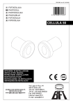
Fotocellula Mod Cellula 50 ad incasso e per applicazione esterna, costituito da una coppia trasmittente ricevente con doppio relè normalmente
eccitato come previsto dalle nomative.
2) DATI TECNICI
Alimentazione
Potenza assorbita
Portata max
Contatti relè
Temperatura funzion.
Grado di protezione
:15÷30 V~
:6,85 VA
:30m (ridotta in caso di nebbia-pioggia)
:1A a 24V~:-10°C ÷ +70°C
:IP54
3) FISSAGGIO DELLE FOTOCELLULE
Dovranno essere installate ad una altezza compresa tra i 40 - 60cm
nei seguenti modi:
- con pilastro in muratura praticare uno scavo in cui inserire il
contenitore di plastica in dotazione che verrà fissato tramite un
riempimento di calcestruzzo (fig.1).
- con pilastro in ferro praticare un foro con una fresa ø 60 in cui
inserire il contenitore di plastica in dotazione. Per il fissaggio del
contenitore praticare tre fori ø 2,7 dove avvitare le tre viti autofilettanti in dotazione (fig.2).
-
se non c’è alcun pilastro o muro dove fissare le fotocellule, richiedere le apposite colonnine metalliche. Le colonnine si possono
fissare direttamente su una base di calcestruzzo con tre tasselli
ad espansione (fig.3).
Il perfetto allineamento al muro è garantito dalle asole di registrazione
presenti sulla base.
4) COLLEGAMENTO ALLA MORSETTIERA (Fig.4)
Trasmittente - Ricevente.
1-2 Alimentazione.
3-4 Contatto normalmente chiuso (con fotocellule allineate il contatto
si apre).
3-5 Contatto normalmente aperto (con fotocellule allineate il contatto
si chiude).
Attenzione! L’installazione deve essere eseguita da personale
qualificato.
5) ALLINEAMENTO DELLE FOTOCELLULE
L’allineamento tra ricevente e trasmittente si ottiene regolando le apposite
viti V (verticale) e O (orizzontale) (fig.5) fino ad ottenere la massima
luminosità del LED interno L.
Si può anche applicare ai due piolini P un voltmetro che ne indichi la
massima tensione (3 V
) corrispondente al massimo allineamento.
6) MANUTENZIONE E DEMOLIZIONE
La manutenzione dell’impianto va fatta eseguire regolarmente da
parte di personale qualificato. I materiali costituenti l’apparecchiatura
e il suo imballo vanno smaltiti secondo le norme vigenti.
Le descrizioni e le illustrazioni del presente manuale non sono
impegnative. Lasciando inalterate le caratteristiche essenziali del
prodotto, la Ditta si riserva di apportare in qualunque momento le
modifiche che essa ritiene convenienti per migliorare tecnicamente,
costruttivamente e commercialmente il prodotto, senza impegnarsi
ad aggiornare la presente pubblicazione.
INSTALLATION MANUAL
Thank you for buying this product, our company is sure that you will
be more than satisfied with the product’s performance. The product is
supplied with a “Warnings” leaflet and an “Instruction booklet”. These
should both be read carefully as they provide important information about
safety, installation, operation and maintenance.This product complies with
the recognised technical standards and safety regulations. We declare
that this product is in conformity with the following European Directives:
73/23/EEC-89/336/EEC (and subsequent amendments).
1) GENERAL OUTLINE (Fig.1)
Cellula 50 Mod recessed photocell to be fitted externally, consisting of a
pair of transmitters and receivers having a double relay which is normally
energised, as provided for by the relevant standards.
2) TECHNICAL SPECIFICATIONS
:15 - 30 V~
Power supply
Absorbed power
:6.85 VA
Max range
:30m (reduced in case of fog / rain)
Relay contacts
:1A at 24V~Working temperature
:-10°C to +70°C
Degree of protection
:IP54
3) PHOTOCELL FITTING
The photocells should be installed between 40 and 60 cm in height,
in the following ways:
- In the case of a masonry pillar, dig a hole where to insert the plastic
container supplied, which is to be secured by concrete filling (fig. 1).
- In the case of an iron pillar, make a hole using a ø 60 cutter where
to insert the plastic container supplied. To secure the container,
make three ø 2.7 holes for fastening the three self-tapping screws
supplied (fig. 2).
- If there is no pillar or wall for the photocells to be secured to, request
the appropriate metal posts. The posts can be directly secured onto a
concrete base by means of three screw anchors (fig. 3).
ITALIANO
ENGLISH
Perfect alignment to the wall is ensured by the adjustment slots
provided in the base.
4) CONNECTION TO THE TERMINAL BOARD (Fig. 4)
Transmitter - Receiver
1-2 Power supply
3-4 Normally closed contact (When photocells are aligned the contact
opens).
3-5 Normally open contact (When photocells are aligned the contact
closes).
Warning! The installation must be carried out by qualified personnel.
5) PHOTOCELL ALIGNMENT
Correct alignment between the receiver and the transmitter is achieved
by adjusting the appropriate V (vertical) and O (horizontal) screws (fig.
5), until maximum luminosity of the internal L LED is obtained.
A voltameter can also be fitted to the two P pins to indicate maximum
voltage (3 V
) which corresponds to maximum alignment.
6) MAINTENANCE AND DEMOLITION
The maintenance of the system should only be carried out by
qualified personnel regularly. The materials making up the set and its
packing must be disposed of according to the regulations in force.
The descriptions and illustrations contained in the present manual
are not binding. The Company reserves the right to make any
alterations deemed appropriate for the technical, manufacturing
and commercial improvement of the product, while leaving the
essential product features unchanged, at any time and without
undertaking to update the present publication.
CELLULA 50 - Ver. 03 - Téléchargé sur www.confort-electrique.fr
Retrouvez tous les produits du fabricant BFT sur notre site internet www.confort-electrique.fr