1
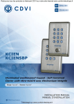
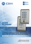
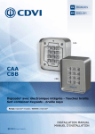
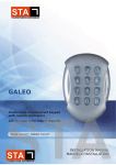
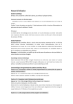
EN
ENGLISH
FR
FRANCAIS
KCIEN
KCIENSBP
Illuminated weatherproof keypad - Self Contained
Clavier codé rétro-éclairé avec électronique intégrée
The installer’s choice
cdvigroup.com
INSTALLATION MANUAL
EN
KCIEN - KCIENSBP
Illuminated Weatherproof Keypad - Self Contained
1] PRODUCT PRESENTATION
139
85
KCIEN
20
Audible and visual feedback.
Dimensions (L x W x D): 140 x 80 x 20mm.
Input voltage:
- 12 V to 24V ac,
- 12 V to 48V dc.
Consumption: 40 to 100mA.
20
Backlit.
Stainless steel.
Compact.
Compact.
2 relays.
Surface mount.
Free voltage.
Installation with Torx® screws.
100 user codes.
DEEE & RoHS
139
TANCE
HIGH RESIS
ISM
TO VANDAL
Recommended
power supplies
IP64
Certification CE
-25°C to +70°C
ARD12
BS60
KCIENSBP
85
2] REMINDERS AND RECOMMENDATIONS
Recommended power supplies
- There are two suitable power supplies
for the encoded keypad:
ARD12 and BS60
- Separate power supply for control components.
Mounting recommendations
Mount the keypad on a flat surface to avoid
any vandalism and to insure the best mounting.
2
cdvigroup.com
Security advice
For security advice reasons, change the factory
default master code. When selecting a master code
and user code avoid simple codes (example : 3 4 5 6 7).
Back EMF protection
To secure the system from back electromagnetic
fields do not forget to mount the varistor
in parallel on the lock.
INSTALLATION MANUAL
EN
KCIEN - KCIENSBP
Illuminated Weatherproof Keypad - Self Contained
3] MOUNTING KIT
KCIEN
KCIENSBP
Varistor
Torx® screw
(M5x8)
T20 Torx
Spanner
(M4x30)
mounting
screws
Plastic anchors
S5
1
1
1
2
2
®
4] MOUNTING INSTRUCTIONS
Once you have made sure that the mounting kit is complete and that you prepared the cables
of the KCIEN/KCIENSBP keypad then you can proceed and mount the product. Make sure that
you have all the appropriate tools (drill, screw drivers and a meter tape...) and follow the
mounting instructions of for the KCIEN/KCIENSBP keypad.
1
2
Place the back plate of the
KCIEN-KCIENSBP on the
wall then mark with a pen
the hole location then drill
the 2 mounting holes (drill
bit Ø5mm and 35MM hole
depth) and the hole wiring
access.
3
Insert
the
2
plastic
anchors in the holes.
Mount the back plate with
the M4x30 screws.
4
Insert the cable in the
hole access area of the
back plate.Then mount
the
keypad
on
the
back plate, placing first
the top in the hook and
then the bottom.
Fasten the KCIEN-KCIENSBP
keypad to the back plate
with the M5x8 TORX®
screw and the T20 TORX®
spanner hardware.
cdvigroup.com
3
INSTALLATION MANUAL
EN
KCIEN - KCIENSBP
Illuminated Weatherproof Keypad - Self Contained
5] PROGRAMMING CHART
Enter the master
code twice
2 x beeps
Illumination
duration
Time Relay 1
Time Relay 2
Code length
Master code
A0
A1
A2
A4
A5
1 x beep
1 x beep
1 x beep
1 x beep
1 x beep
10 - 99 sec
00 = Permanent
10 = Default
01 - 99 sec
00 = Toggle
01 = Default
01 - 99 sec
00 = Toggle
01 = Default
4, 5 or 6 digits
5 = Default
All digits are valid
1 2 3 4 5 = Default
1 x beep = OK
4 beeps = error
1 x beep = OK
4 beeps = error
1 x beep = OK
4 beeps = error
1 x beep = OK
4 beeps = error
1 x beep = OK
4 beeps = error
Press B to exit
from programming
KCIEN-KCIENSBP
2 beeps
4
cdvigroup.com
INSTALLATION MANUAL
EN
KCIEN - KCIENSBP
Illuminated Weatherproof Keypad - Self Contained
Reset
Sub master
code 1
Sub master
code 2
Buzzer
(audible
feedback)
User codes
A6
A7
A8
AA
00-99
1 x beep
1 x beep
1 x beep
1 x beep
2 digits
AB = Default
2 digits
13 = Default
0 = Buzzer
disabled
1 = Buzzer enabled
1 x beep = OK
4 beeps = error
1 x beep = OK
4 beeps = error
1 x beep = OK
4 beeps = error
4, 5 ou 6 digit code
Press A
Then B
2 Beeps
are emitted
4 beeps = User
location: “Used”
1 beep = User
location: “Free”
1 x beep = OK
KCIEN-KCIENSBP
cdvigroup.com
5
INSTALLATION MANUAL
EN
KCIEN - KCIENSBP
Illuminated Weatherproof Keypad - Self Contained
6] WIRING DIAGRAM
Black
Power supply
12V to 24V ac
or 12V to 48V dc
Red
Dark green
H2
Purple
Pink
Light blue
H1
Light green
Blue red
Pink Grey
Green white
Magnetic lock
Brown
Orange
Strike
Power control side
power supply
Yellow
KCIEN
KCIENSBP
Front side
ST3
Resetting
memory
KCIEN
KCIENSBP
Back side
White
Electric strike
Grey
Varistor
Outputs
Description
Black
Input voltage 12V to 24V ac or 12V to 48V dc
Red
Input voltage 12V to 24V ac or 12V to 48V dc
Pink
Relay 1 request to exit input
Purple
Common
Dark green
Clock switch (H1)
Green White
Relay 2 N/C contact
Blue red
Relay 2 common
Pink gray
Relay 2 N/O contact
Orange
Relay 1 N/C contact
Yellow
Relay 1 common
Brown
Relay 1 N/O contact
Light blue
Request-to- enter input
Light green
User code change
White
Tamper switch output
Grey
Tamper switch output
This product is supplied with a varistor.
It should be mounted on the terminal of electric release (electromagnetic lock, solenoid bolt, etc ...) controlled
by the device.If this device controls more than one electronic release, then each lock should be fitted
with a varistor. The varistor controls the overload produced by the strike coil - back emf. It is recommended
to use a separate power supply when using a Shear Lock Magnet.
6
cdvigroup.com
INSTALLATION MANUAL
EN
KCIEN - KCIENSBP
Illuminated Weatherproof Keypad - Self Contained
Description:
12V to 24V ac power supply or 12V to 48V dc.
Illuminated 12 key keypad.
Non-volatil EPROM memory.
100 programmable codes
in 4, 5 or 6 digits.
2 form “C” contact N/O & N/C 6A/250V~.
Master code programmable
in 4, 5 or 6 digits.
Warning buzzer.
1 request - to - exit input.
Factory master code and code reset.
Code change by the user
Default values:
No codes.
Illumination time: 10 seconds.
Relay release time: 1 second.
Code length: 5-digits.
Master Code: 1 2 3 4 5.
Programming security-lag: 120s.
Code length for sub master code:
- Version 1 relay (Group 1) = A and B,
- Version 2 relays (Group 2) = 1 and 3.
One beep on switching on.
Audible signal correspondence:
- 1 short beep: Keypad powered
- 1 long beep: data computing
in programming or access granted.
- 2 beeps: Enter or Exit
from programming.
- 4 short beeps: data computing error.
Digits used and opening codes:
- The master code and the User codes
can be of 4 or 5-digit in length.
All the keypad keys can be used
to program a code. The master code
and the Pin code can be of 4, 5
or 6-digit code. The master code can not be used as a PIN code
(User Pin code).
- Codes 0 0 0 0 0 0, 0 0 0 0 0
and 0 0 0 0 can only be used
to delete a user Pin code.
Control by push button:
- The connection of push button P1
is intended for controlling relay 1.
(the mode and the time-lag
can be programmed).
- Clock contact H1 enables use
of the outside button for free
opening. Clock contact H2 enables
use of all the keys as outside buttons.
If the clock contact is open, the keys
are used like normal digits.
If the clock contact is closed,
all the keys can be used for free access.
Consumption
(without the control elements)
With the 2 relays controlled
and permanent lighting:
- In 12V dc > 90mA max,
- In 12V ac > 70mA max,
- In 24V dc > 50mA max,
- In 24V ac > 40mA max.
A. Resetting the memory
B. Setting code length
1. Enter the master code twice.
- For the first use, the factory
master code is: 1 2 3 4 5.
- Two beeps are emitted to confirm entry in programming mode.
1. Enter the master code twice.
- For the first use, the factory
master code is: 1 2 3 4 5.
- Two beeps are emitted to confirm entry in programming mode.
2. Then press A6.
- A short beep sounds is emitted.
- Press A and B to confirm the resetting. - Wait for a beep to be emitted
and for the lighting to go off.
- The master code is 1 2 3 4 5 again
and all the codes have been erased.
- The keypad is reinitialised.
- The keypad is no longer
in the programming mode and the default values have been restored.
2. Press A4 to input the number of digits in the codes.
- A short beep sounds is emitted.
- Enter 4, 5 or 6 for number of digits.
- A long beep sounds is emitted to confirm
the programming.
OR
1. Turn off the power supply.
Place a jumper at ST3 (See P. 6). 2. Turn the power supply on again.
Wait a few seconds, a beep is emitted.
3. The master code is 12345 again
and all the codes have been erased.
The default values have been restored.
3. Press A5 to change the master code.
- A short beep sounds is emitted.
- Enter the 4, 5 or 6 digits of the new
master code.
- A long beep sounds is emitted to confirm
programming of the newmaster code.
4. Press B to exit from
the programming mode.
Two beeps sound are emitted to confirm the return to the normal mode of operation.
4 beeps indicate a data computing error.
cdvigroup.com
7
INSTALLATION MANUAL
EN
KCIEN - KCIENSBP
Illuminated Weatherproof Keypad - Self Contained
Example:
You have a 5-digit master code and 5-digit user
codes. You want to use 4-digit user codes.
When the number of digits in the master code
has effectively changed from 5 to 4, the user
codes become 4-digit codes at the same time.
E.g.: If your master code and user code is 1 2 3 6 9,
after the operation it will become 2 3 6 9.
If you want to switch from a master code (to one
of 5 digits follow the same procedure.
When changing from 4 to 5 digits, the figure “O”
will be added by default in front of the master
code and hence in front of the user codes.
Ex : The change from the master code 2 3 6 9
with 4 digits to one with 5 digits becomes 0 2 3 6 9.
We advise programming the codes
as 6 digits and then modifying
the code length.
C. CHANGING THE MASTER CODE
The master code is used only to enter
in programming mode.
1. Enter the master code twice.
- For the first use the factory
master code is : 1 2 3 4 5.
- Two beeps sound are emitted to confirm entry into the programming mode.
2. Press A5 to modify the master code.
- A short beep sounds is emitted.
- Enter the 4, 5 or 6 digits
of the new master code.
- A long beep sounds is emitted to confirm that the master code is programmed.
3. Press B to exit from the programming mode.
Two beeps sound are emitted to confirm the return to the normal mode of operation.
D. Adding, changing or deleting
a user code
Relay 1
Group 1 : From digit place 00 to digit place 59,
Relay 2
Group 2 : From digit place 60 to digit place 99.
1. Enter the master code twice.
- For the first use the factory master code
is : 1 2 3 4 5.
8
cdvigroup.com
- Two beeps sound are emitted to confirm entry into the programming mode.
- Enter the master code twice:
Master code
Master code
2 beeps
2. Enter the user location
to be programmed (from 00 to 99).
- If the digit place is free, a short beep sounds, enter the 4, 5 or 6 digits of the code.
- If the digit place is occupied, 4 beeps sound.
- Enter the 4, 5 or 6 digits of the code
or enter 0 0 0 0 0 0 or 0 0 0 0 0 or 0 0 0 0
to cancel the existing code.
- If the Pin code is already programmed
or is identical to the master code,
then 4 beeps are emitted.
- Codes 0 0 0 0 0 0 or 0 0 0 0 0
or 0 0 0 0 serve to cancel an existing code and hence cannot be used
as an usual code.
3. Press B to exit from the programming mode.
- Two beeps sound are emitted to confirm the return to the normal mode of operation.
E. Time outputs
1. Enter the master code twice.
- For the first use, the factory
master code is: 1 2 3 4 5.
- Two beeps sound are emitted to confirm entry into the programming mode.
2. Enter A0 for the key-in keypad time.
- One short beep sound is emitted.
- Enter the duration time in seconds.
E.g. : From 10 for 10 seconds to 99
for 99 seconds or enter 00 for a permanent illumination. A long beep sounds to confirm the programming.
3. Press A1 for output time of relay 1
- A short beep sounds is emitted.
- Enter the duration in seconds.
E.g.: 01 for 1 second up to 99 for 99 sec. Enter 00 for a toggled output. One beep
is emitted to validate the time.
4. Press A2 for the output time of relay 2.
- A short beep sounds is emitted.
- Enter the time in seconds. INSTALLATION MANUAL
EN
KCIEN - KCIENSBP
Illuminated Weatherproof Keypad - Self Contained
E.g.: 01 for 1 second up to 99 for 99 seconds.
Enter 00 for a toggled output. One beep
is emitted to validate the time.
- Enter the two digits of the modifications.
- A long beep sounds are emitted
to confirm the programming.
5. To exit from the programming mode, press B.
Two beeps sound to confirm the return
to the normal mode of operation.
3. Press A8 to input modification digits
for group 2 user codes.
- A short beep sounds is emitted.
- Enter the two digits of the modifications. - A long beep sounds to confirm
programming.
4 beeps signal an input error.
F. Resetting the master code
In normal operation, place a jumper at ST3.
Wait for a beep to sound.
Remove the jumper. The master code is again 1 2 3 4 5 6
in 6 digits, 1 2 3 4 5 in 5 digits or 1 2 3 4 in 4 digits.
G. Changing the code by the user
To authorize a user to modify its own User
code connect together the light green
and the purple wires
1. Enter the old user code.
The relay is activated and a beep
is emitted.
2. Enter the 2-digit sub master code (default sub master code A and B).
A beep is emitted to authorise
the modification.
3. Enter the new user code.
2 beeps are emitted to confirm
the new code.
4. Check the new user code to be sure
of the modification.
H. Setting a sub master code
4. Press B to exit from the programming mode.
Two beeps sound are emitted to confirm
the return to the normal mode of operation.
I. Programming the audible signal
The audible signal is always audible
during programming.
It is also audible on a command to open,
following the recognition of a code.
By default, when the opening code
is entered, no “key” beep is audible.
It is possible to authorise key beeps
by proceeding as follows:
1. Enter the master code twice.
- For the first use the factory
master code is : 1 2 3 4 5.
- Two beeps sound are emitted to confirm entry into the programming mode.
2. Press AA.
- One beep is emitted.
- Press 0 to disable the audible signal during a keypress.
- Press 1 to enable the audible signal during a keypress.
- A beep is emitted to confirm the new
setting.
3. Press B to exit from the programming mode.
Two beeps sound are emitted to confirm the return to the normal operating mode.
1. Enter the master code twice.
- For the first use the factory
master code is : 1 2 3 4 5.
- Two beeps sound are emitted to confirm entry into the programming mode.
2. Press A7 to input modification digits
for group 1 user codes.
- A short beep sounds is emitted.
cdvigroup.com
9
INSTALLATION MANUAL
EN
KCIEN - KCIENSBP
Illuminated Weatherproof Keypad - Self Contained
User code table.
User
location
Code
Name
Forename
User
location
Code
Name
Forename
User
location
00
34
68
01
35
69
02
36
70
03
37
71
04
38
72
05
39
73
06
40
74
07
41
75
08
42
76
09
43
77
10
44
78
11
45
79
12
46
80
13
47
81
14
48
82
15
49
83
16
50
84
17
51
85
18
52
86
19
53
87
20
54
88
21
55
89
22
56
90
23
57
91
24
58
92
25
59
93
26
60
94
27
61
95
28
62
96
29
63
97
30
64
98
31
65
99
32
66
33
67
REMINDER
10
cdvigroup.com
KCIEN-KCIENSBP 1 Relay
Group 1: User location 00 to 59.
Code
Name
Forename
KCIEN-KCIENSBP 2 Relays
Group 2 : User location 60 to 99.
INSTALLATION MANUAL
EN
KCIEN - KCIENSBP
Digicode® 2 relais avec électronique intégrée
1] PRESENTATION DU PRODUIT
139
85
KCIEN
20
Signalisation lumineuse et sonore.
Dimensions (L x l x P) : 140 x 80 x 20 mm.
Alimentation :
- 12 V à 24 V AC,
- 12 V à 48 V DC.
Consommation : de 40 à 100 mA.
20
Rétro-éclairé.
Inox.
Compact.
Faible encombrement.
2 relais.
Pose en applique.
Free voltage**.
Montage vis Torx®.
100 codes utilisateurs.
** Tension libre
DEEE & RoHS
139
TANCE
HAUTE RÉSIS
ISME
AU VANDAL
Recommended
power supplies
IP64
Certification CE
-25°C à +70°C
ARD12
BS60
KCIENSBP
85
2] RAPPELS ET RECOMMANDATIONS
Alimentations préconisées
- Il existe deux alimentations adaptées
pour le clavier codé :
ARD12 et BS60.
- Alimentation séparée pour les éléments
de commande.
Composition des codes
- Par soucis de sécurité, veillez à modifier le code maître usine par celui de votre choix.
- Lors du changement du code maître usine
et de la création des codes utilisateurs, évitez
les codes trop simples (ex: les suites 3 4 5 6 7).
Montage
Afin d’optimiser la fixation du KCIEN-KCIENSBP
et de prévenir les tentatives d’arrachage,
privilégiez les surfaces planes.
Recommandations d’installation
Pour sécuriser l’installation, n’oubliez pas de placer
la varistance sur le système de verrouillage,
en parallèle, au niveau de l’alimentation.
cdvigroup.com
11
MANUEL D’INSTALLATION
FR
KCIEN - KCIENSBP
Digicode® 2 relais avec électronique intégrée
3] KIT DE MONTAGE
Varistance
05D 680K
Vis Torx® à tête
fraisée (M5x8)
Clé mâle coudée
pour vis Torx®
(T20)
Vis cruciforme
à tête fraisée
(M4x30)
Cheville
S5
1
1
1
2
2
KCIEN
KCIENSBP
4] MONTAGE
Après avoir vérifié que le kit de montage est complet, vous allez pouvoir procéder
à l’installation finale du produit. Réunissez le matériel approprié (Perçeuse, tournevis,
mètre,...) et suivez les recommandations de montage du KCIEN-KCIENSBP.
1
2
Positionner les 2 chevilles
plastique S5 dans les
trous. Fixer le fond du
KCIEN-KCIENSBP sur le
support à l’aide des vis
cruciforme à têtes
fraisées M4x30.
Percer (forêt Ø5mm)
les 2 trous de fixation
(profondeur mini.
= 35mm) ainsi que
l’ouverture pour le passage
du câble électrique.
3
4
Passer le câble électrique
du KCIEN-KCIENSBP
dans son ouverture.
Poser ensuite le Digicode®
contre son fond, du haut
vers le bas, en l’assemblant
tout d’abord avec le
crochet supérieur.
12
cdvigroup.com
Fixer le Digicode®
avec son fond (logement
dans le bas du produit)
par l’intermédiaire
de la vis TORX® M5x8
et de son outil spécifique
(clé mâle coudée T20).
MANUEL D’INSTALLATION
FR
KCIEN - KCIENSBP
Digicode® 2 relais avec électronique intégrée
5] SCHÉMA DE RACCORDEMENTS
Noir
Alimentation
12 à 24 V AC
ou 12 à 48 V DC
Rouge
Vert foncé
H2
Violet
Rose
Bleu clair
Vert clair
H1
Bleu rouge
Rose gris
Ventouse
Vert blanc
Marron
Orange
Gâche
Alimentation
côté commande
de puissance
Jaune
KCIEN
KCIENSBP
Face
ST3
RAZ
KCIEN
KCIENSBP
Arrière
Blanc
Gâche à émission
Gris
Varistance
Sorties
Correspondance
Noir
Alimentation 12 V à 24 V AC ou 12 V à 48 V DC
Rouge
Alimentation 12 V à 24 V AC ou 12 V à 48 V DC
Rose
Bouton intérieur de sortie relais 1
Violet
Commun
Vert foncé
Contact horloge H2
Vert blanc
Contact repos du relais 2
Bleu rouge
Commun du relais 2
Rose gris
Contact travail du relais 2
Orange
Contact repos du relais 1
Jaune
Commun du relais 1
Marron
Contact travail du relais 1
Bleu clair
Contact horloge bouton extérieur H1
Vert clair
Changement de code utilisateur
Blanc
Sortie anti-arrachement
Gris
Sortie anti-arrachement
Ce produit est livré avec une varistance .
Celle-ci doit être montée directement sur les bornes de la gâche (ventouse, …) commandée par l’équipement.
Si l’appareil fonctionne avec plusieurs gâches, chacune doit être équipée de varistance. La varistance limite
les surtensions provoquées par le bobinage de la gâche – effet de self. Dans le cas où la ventouse utilisée
est du type « Shear Lock », celle-ci doit être alimentée par une alimentation indépendante du KCIEN-KCIENSBP.
cdvigroup.com
13
MANUEL D’INSTALLATION
FR
KCIEN - KCIENSBP
Digicode® 2 relais avec électronique intégrée
Description:
- Alimentation : 12 V à 24 V AC
ou 12 V à 48 V DC.
- Clavier 12 touches lumineux.
- Sauvegarde mémoire permanente E2PROM.
- 100 codes programmables
en 4, 5 ou 6 termes.
- 2 relais d’ouverture 1 contact RT 6 A / 250 V~.
- Code maître programmable
en 4, 5 ou 6 termes.
- Buzzer de signalisation.
- 1 bouton poussoir de sortie commandant l’ouverture.
- Code maître usine et raz
des codes.
- Modification des codes
par l’utilisateur
Valeurs par défaut:
- Aucun code.
- Tempo éclairage : 10 s.
- Tempo d’ouverture
pour tous les relais : 1 s.
- Nombre de termes : 5.
- Code maître usine : 1 2 3 4 5.
- Tempo sécurité programmation : 120 s.
- Codes de modification par utilisateur pour le 1er groupe: A et B.
- Codes de modification
par utilisateur pour le 2ème groupe: 1 et 3.
- Un bip à la mise sous tension.
Correspondance des signaux
sonores :
- 1 bip court : Mise sous tension
- 1 bip long : Validation d’une saisie
en programmation et ouverture
- 2 bips : courts Entrée ou sortie
de programmation
- 4 bips courts : Erreur de saisie.
Termes utilisés et codes
d’ouverture:
- Toutes les touches du clavier
sont autorisées pour composer
les codes.
- Le code maître et les codes d’ouverture de porte doivent être composés de 4, 5 ou 6 termes.
- Le code maître ne peut pas être utilisé comme code d’ouverture.
- Les codes 0 0 0 0 0 0 ou 0 0 0 0 0
ou 0 0 0 0 servent à annuler
un code existant et ne peuvent A. Remise à zéro de la mémoire
1. Tapez 2 fois le code maître.
- Pour la première utilisation,
le code maître usine est : 1 2 3 4 5.
- Deux bips sonores sont émis
pour confirmer l’entrée en programmation.
2. Puis tapez A6.
- Un bip court est émis.
- Tapez A et B pour valider la remise à zéro.
- Attendre qu’un bip soit émis
et que l’éclairage s’éteignent.
- Le code maître est de nouveau 1 2 3 4 5
et tous les codes sont effacés.
- Le clavier est réinitialisé.
- Le clavier est sorti de programmation
et les valeurs par défaut sont rétablies.
OU
1. Coupez l’alimentation.
Positionnez un cavalier en ST3 (Voir P. 13).
2. Rétablir l’alimentation.
Attendre quelques secondes,
un bip est émis. Enlevez le cavalier ST3.
14
cdvigroup.com
donc pas servir comme code
d’ouverture de porte.
Commande par bouton poussoir:
- Le raccordement du bouton poussoir
P1 est prévu pour commander le relais 1 (le mode et la temporisation
sont programmables).
- Le contact horloge H1 permet
l’utilisation du bouton extérieur
pour l’ouverture libre.
- Le contact horloge H2 permet
l’utilisation de toutes les touches comme bouton extérieur.
- Si le contact horloge est ouvert,
les touches sont utilisées comme
des termes habituels.
- Si le contact horloge est fermé,
toutes les touches sont utilisées
pour l’ouverture libre.
Consommation
(sans les éléments de commande)
Avec les 2 relais commandés
et l’éclairage permanent :
- En 12 V DC : 90 mA max,
- En 12 V AC : 70 mA max,
- En 24 V DC : 50 mA max,
- En 24 V AC : 40 mA max.
3. Le code maître est de nouveau
1 2 3 4 5 et tous les codes sont effacés.
Les valeurs par défaut sont rétablies.
B. Programmation du nombre
de termes
1. Tapez 2 fois le code maître.
- Pour la première utilisation,
le code maître usine est : 1 2 3 4 5.
- Deux bips sonores sont émis
pour confirmer l’entrée en programmation.
2. Tapez A4 pour la saisie
du nombre de termes des codes.
- Un bip court est émis .
- Tapez 4, 5 ou 6 pour le nombre de termes
- Un bip long est émis pour confirmer
la programmation.
3. Tapez A5 pour changer
le code maître.
- Un bip court est émis.
- Tapez les 4, 5 ou 6 termes du nouveau code maître.
MANUEL D’INSTALLATION
FR
KCIEN - KCIENSBP
Digicode® 2 relais avec électronique intégrée
- Un bip long est émis pour confirmer
la programmation.
4. Tapez B pour sortir de la programmation.
Deux bips sont émis pour confirmer
le retour au mode normal de fonctionnement.
4 bips indiquent une erreur de saisie
Cas de figure :
Vous avez un code maître et des codes
utilisateurs à 5 termes. Vous souhaitez utiliser des codes à 4 termes. Vous faites donc la démarche indiquée ci-dessus
en modifiant le code maître.
Lorque le nombre de terme du code maître est bien passé de 5 à 4 termes, les codes utilisateurs deviennent simultanément
des codes à 4 termes.
Ex : Si votre code maître et code utilisateur
est 1 2 3 6 9, il deviendra après manipulation
2 3 6 9. Si vous souhaitez passer d’un code maître (et donc d’un code utilisateur)
de 4 termes à 5 termes suivez la même
procédure. Lors du passage de 4 à 5 termes,
le chiffre «O» sera intégrer par défaut devant le code maître et donc devant les codes utilisateurs.
Ex : le passage du code maître 2 3 6 9
à 4 termes en 5 termes devient 0 2 3 6 9.
Il est conseillé de programmer
les codes en 6 termes puis
de modifier le nombre de termes.
C. Programmation du code maître
1. Tapez 2 fois le code maître.
- Pour la première utilisation,
le code maître usine est : 1 2 3 4 5.
- Deux bips sonores sont émis
pour confirmer l’entrée en programmation.
2. Tapez A5.
- Un bip court est émis.
- Tapez les 4, 5 ou 6 termes du nouveau code maître.
- Un bip long est émis pour confirmer
la programmation.
3. Tapez B pour sortir de la programmation.
Deux bips sont émis pour confirmer
le retour au mode normal de fonctionnement.
D. Programmation des codes
Relais 1
Groupe 1 : Du rang 00 au rang 59,
Relais 2
Groupe 2 : Du rang 60 au rang 99.
1. Tapez 2 fois le code maître.
- Pour la première utilisation,
le code maître usine est : 1 2 3 4 5.
- Deux bips sonores sont émis
pour confirmer l’entrée en programmation.
- Pour programmer des codes :
Code Maître
Code Maître
2 bips
2. Tapez le n° du rang à programmer
(de 00 à 99).
- Si le rang est libre, un bip court est émis, tapez les 4, 5 ou 6 termes du code.
- Si le rang est occupé, 4 bips sont émis. - Tapez les 4, 5 ou 6 termes du code
ou tapez 0 0 0 0 0 0 ou 0 0 0 0 0
ou 0 0 0 0 pour annuler le code existant.
- Un bip long est émis pour confirmer
la programmation.
- Si le code entré correspond à un code existant ou s’il est identique au code
maître, 4 bips sont émis pour indiquer une erreur.
- Les codes 0 0 0 0 0 0 ou 0 0 0 0 0
ou 0000 servent à annuler un code
existant et ne peuvent donc pas servir comme code d’ouverture de porte.
3. Tapez B pour sortir de la programmation.
Deux bips sont émis pour confirmer le retour
au mode normal de fonctionnement.
E. Programmation des temporisations
1. Tapez 2 fois le code maître.
- Pour la première utilisation,
le code maître usine est : 1 2 3 4 5.
- Deux bips sonores sont émis
pour confirmer l’entrée en programmation.
2. Tapez A0 pour la temporisation du clavier.
- Un bip court est émis.
cdvigroup.com
15
MANUEL D’INSTALLATION
FR
KCIEN - KCIENSBP
Digicode® 2 relais avec électronique intégrée
- Tapez la durée de commande en secondes.
Ex : de 10 pour 10 secondes à 99 pour 99 secondes ou tapez 00 pour obtenir
un éclairage permanent. Un bip long
est émis pour confirmer la programmation.
3. Tapez A1 pour la temporisation
du relais 1.
- Un bip court est émis.
- Tapez la durée de commande en secondes.
Ex : 01 pour 1 seconde jusqu’à 99
pour 99 secondes. La durée 00 correspond
au fonctionnement bistable du relais 1.
Un bip long est émis pour confirmer.
4. Tapez A2 pour la temporisation
du relais 2.
- Un bip court est émis.
- Tapez la durée de commande en secondes
Ex : 01 pour 1 seconde jusqu’à 99
pour 99 secondes. La durée 00 correspond au fonctionnement bistable du relais 1.
Un bip long est émis pour confirmer la programmation.
5. Pour sortir de la programmation,
tapez B.
Deux bips sont émis pour confirmer
le retour au mode normal de fonctionnement.
4 bips indiquent une erreur de saisie
F. Remise à zéro du code maître
- En fonctionnement normal, positionnez
un cavalier en ST3.
- Attendre qu’un bip soit émis.
- Enlevez le cavalier.
- Le code maître est de nouveau 1 2 3 4 5 6 en 6 termes, 1 2 3 4 5 en 5 termes
ou 1 2 3 4 en 4 termes.
G. Changement du code d’entrée
par l’utilisateur
(Fil vert clair et fil violet)
L’autorisation de changement de code
par l’utilisateur est déterminée
par le raccordement du fil vert clair
au fil violet ( aucun raccordement
pour interdire le changement de code )
1. Composez le code utilisé actuellement.
- Le relais d’ouverture est commandé.
16
cdvigroup.com
- Un bip long est émis.
2. Tapez immédiatement les 2 termes
du code de modification.
(A et B ou 1 et 3 à la première utilisation).
Un bip long est émis pour autoriser
le changement.
3. Composez le nouveau code d’ouverture.
- Deux bips sont émis confirmant la validation
du nouveau code et le retour
à un fonctionnement normal.
- L’éclairage s’éteint.
4. Vérifiez la mémorisation du nouveau
code en le composant.
H. Programmation des termes
de modifications
1. Tapez 2 fois le code maître.
- Pour la première utilisation, le code maître
usine est : 1 2 3 4 5.
- Deux bips sont émis pour confirmer l’entrée en programmation.
2. Tapez A7 pour la saisie des termes de modifications des codes
utilisateurs du groupe 1.
- Un bip court est émis.
- Tapez les deux termes de modifications.
- Un bip long est émis pour confirmer
la programmation.
3. Tapez A8 pour la saisie des termes de modifications des codes
utilisateurs du groupe 2.
- Un bip court est émis.
- Tapez les deux termes de modifications. - Un bip long est émis pour confirmer
la programmation.
4. Tapez B pour sortir de la programmation.
Deux bips sont émis pour confirmer
le retour au mode normal de fonctionnement.
I. Programmation du signal sonore
Le signal sonore est toujours audible
en programmation. Il en est de même lors de la commande d’ouverture,
suite à la reconnaissance d’un code.
Par défaut, lors de la composition du code d’ouverture, aucun bip sonore «touche» n’est audible.
MANUEL D’INSTALLATION
FR
KCIEN - KCIENSBP
Digicode® 2 relais avec électronique intégrée
- Il est possible d’autoriser les bips touches en faisant comme suit :
1. Tapez 2 fois le code maître.
- Pour la première utilisation,
le code maître usine est : 1 2 3 4 5.
- Deux bips sonores sont émis pour confirmer l’entrée en programmation.
2. Tapez AA.
- Un bip est émis.
- Tapez 0 pour supprimer les bips touches pendant la composition du code
d’ouverture.
- Tapez 1 pour autoriser les bips touches pendant la composition du code d’ouverture.
- Un bip sonore est émis pour confirmer
la programmation.
3. Tapez B pour sortir de la programmation.
Deux bips sonores sont émis pour confirmer
le retour au mode normal de fonctionnement.
Ci-joint un tableau récapitulatif qui vous servira à indiquer le code attribué à chaque utilisateur
Rangs
Code
Nom
Prénom
Rangs
Code
Nom
Prénom
Rangs
00
34
68
01
35
69
02
36
70
03
37
71
04
38
72
05
39
73
06
40
74
07
41
75
08
42
76
09
43
77
10
44
78
11
45
79
12
46
80
13
47
81
14
48
82
15
49
83
16
50
84
17
51
85
18
52
86
19
53
87
20
54
88
21
55
89
22
56
90
23
57
91
24
58
92
25
59
93
26
60
94
27
61
95
28
62
96
29
63
97
30
64
98
31
65
99
32
66
33
67
RAPPEL
KCIEN-KCIENSBP 1 Relais
Groupe 1 : Du rang 00 au rang 59.
Code
Nom
Prénom
KCIEN-KCIENSBP 2 Relais
Groupe 2 : Du rang 60 au rang 99.
cdvigroup.com
17
MANUEL D’INSTALLATION
FR
KCIEN - KCIENSBP
Digicode® 2 relais avec électronique intégrée
6] PROGRAMMATION
Tapez 2 fois
le code maitre
2 x bips
Temporisation
éclairage
clavier
Temporisation
relais 1
Temporisation
relais 2
Nombre de
termes
Code maître
A0
A1
A2
A4
A5
1 x bip
1 x bip
1 x bip
1 x bip
1 x bip
10-99 sec
00 = continue
10=Défaut
01-99 sec
00 = bistable
01=Défaut
01-99 sec
00 = bistable
01=Défaut
4’,5’ ou 6 chiffres
5= Défaut
Toutes les
touches
sont valides
12345 = Défaut
1 x bip = OK
4 bips = erreur
1 x bip = OK
4 bips = erreur
1 x bip = OK
4 bips = erreur
1 x bip = OK
4 bips = erreur
1 x bip = OK
4 bips = erreur
Tapez B pour sortir
de la programmation
KCIEN-KCIENSBP
2 bips
18
cdvigroup.com
MANUEL D’INSTALLATION
FR
KCIEN - KCIENSBP
Digicode® 2 relais avec électronique intégrée
Reset
Termes
de modification
relais 1
Termes
de modification
relais 2
Signal sonore
Programmation
des codes
A6
A7
A8
AA
00-99
1 x bip
1 x bip
1 x bip
1 x bip
2 chiffres
AB=défaut
2 chiffres
13=défaut
0=supprimer
les bips
1 = autoriser
les bips
1 x bip = OK
4 bips = erreur
1 x bip = OK
4 bips = erreur
1 x bip = OK
4 bips = erreur
Tapez A
ensuite B
2 Bips sont émis
4, 5 ou 6 chiffres
4 bips = rang
occupé
1 bip = rang libre
1 x bip = ok
KCIEN-KCIENSBP
cdvigroup.com
19
Reference : G0301FR0265V06
Extranet : EXE-CDVI_IM KCIEN-KCIENSBP CMYK A5 EN-FR 04
*G0301FR0265V06*
CDVI Group
FRANCE (Headquarter/Siège social)
Phone: +33 (0)1 48 91 01 02
Fax: +33 (0)1 48 91 21 21
[CANADA - USA]
Phone: +1 (450) 682 7945
Fax: +1 (450) 682 9590
CDVI
BENELUX
[BELGIUM - NETHERLAND - LUXEMBOURG]
Phone: +32 (0) 56 73 93 00
Fax: +32 (0) 56 73 93 05
CDVI
TAIWAN
Phone: +886 (0)42471 2188
Fax: +886 (0)42471 2131
CDVI
SUISSE
Phone: +41 (0)21 882 18 41
Fax: +41 (0)21 882 18 42
CDVI
CHINA
Phone: +86 (0)10 62414516
Fax: +86 (0)10 62414519
[SPAIN - PORTUGAL]
Phone: +34 (0)935 390 966
Fax: +34 (0)935 390 970
CDVI
ITALIA
Phone: +39 0331 97 38 08
Fax: +39 0331 97 39 70
CDVI
MAROC
Phone: +212 (0)5 22 48 09 40
Fax: +212 (0)5 22 48 34 69
CDVI
SWEDEN
[SWEDEN - DENMARK - NORWAY - FINLAND]
Phone: +46 (0)31 760 19 30
Fax: +46 (0)31 748 09 30
CDVI
UK
[UNITED KINGDOM - IRELAND]
Phone: +44 (0)1628 531300
Fax: +44 (0)1628 531003
DIGIT
FRANCE
Phone: +33 (0)1 41 71 06 85
Fax: +33 (0)1 41 71 06 86
Toutes les informations mentionnées à titre indicatif sur le présent document (photos, dessins, caractéristiques
techniques et dimensions) peuvent varier et sont susceptibles de modifications sans notification préalable.
CDVI AMERICAS
CDVI
IBÉRICA
All the information contained within this document (pictures, drawing, features, specifications and dimensions)
could be perceptibly different and can be changed without prior notice.
CDVI
FRANCE + EXPORT
Phone: +33 (0)1 48 91 01 02
Fax: +33 (0)1 48 91 21 21
The installer’s choice
cdvigroup.com