1
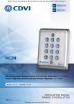
INSTALLATION MANUAL
EN
KCIEN - KCIENSBP
Illuminated Weatherproof Keypad - Self Contained
6] WIRING DIAGRAM
Black
Power supply
12V to 24V ac
or 12V to 48V dc
Red
Dark green
H2
Purple
Pink
Light blue
H1
Light green
Blue red
Pink Grey
Green white
Magnetic lock
Brown
Orange
Strike
Power control side
power supply
Yellow
KCIEN
KCIENSBP
Front side
ST3
Resetting
memory
KCIEN
KCIENSBP
Back side
White
Electric strike
Grey
Varistor
Outputs
Description
Black
Input voltage 12V to 24V ac or 12V to 48V dc
Red
Input voltage 12V to 24V ac or 12V to 48V dc
Pink
Relay 1 request to exit input
Purple
Common
Dark green
Clock switch (H1)
Green White
Relay 2 N/C contact
Blue red
Relay 2 common
Pink gray
Relay 2 N/O contact
Orange
Relay 1 N/C contact
Yellow
Relay 1 common
Brown
Relay 1 N/O contact
Light blue
Request-to- enter input
Light green
User code change
White
Tamper switch output
Grey
Tamper switch output
This product is supplied with a varistor.
It should be mounted on the terminal of electric release (electromagnetic lock, solenoid bolt, etc ...) controlled
by the device.If this device controls more than one electronic release, then each lock should be fitted
with a varistor. The varistor controls the overload produced by the strike coil - back emf. It is recommended
to use a separate power supply when using a Shear Lock Magnet.
6
cdvigroup.com