1
d2 Procédure d'installation
(v.02/02)
Etapes à suivre lors de l’installation d’un ventilateur TACd2:
1) Monter le ventilateur.
2) Monter le boîtier de puissance et le connecter au moteur.
3) Raccorder l’alimentation 230V au boîtier de puissance (raccordement à la terre obligatoire).
Assurer la protection à l’aide d’un disjoncteur approprié (voir manuel d’installation §9).
4) Monter le boîtier de contrôle TACd2.
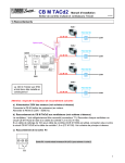
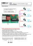
5) Connecter le boîtier de puissance au boîtier de contrôle à l’aide du câble RJ45. Détail: voir
manuel d’installation au §1.
6) Si vous constatez un clignotement des LED 1 et 2 sur le boîtier de contrôle lors de sa mise en
service, référez-vous au document ‘troubleshooting’.
7) Si un seul débit est nécessaire:
- Positionner les dip-switches 1 à 5 du boîtier TACd2 en fonction du débit voulu. Voir
tableau en annexe 1 du manuel d’installation.
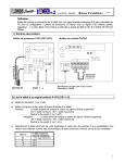
- Raccorder le contact de softstop (marche/arrêt du ventilateur sans couper la puissance:
obligatoire) entre les bornes 3 et 6.
- Détail : voir manuel d’installation au §2.
Si 2 ou 3 débits sont nécessaires:
- Positionner les dip-switches 1 à 5 du boîtier TACd2 en fonction du débit maximum voulu
(100%). Voir tableau en annexe 1 du manuel d’installation.
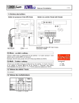
- Raccorder les contacts externes (bornes 3-6 et 4-6) permettant l’activation des
multiplicateurs 33%, 66% et 100%. L’arrêt du ventilateur doit se faire par l’ouverture des 2
contacts. Un commutateur 4 positions de type EDS4 peut également être utilisé (se
référer au manuel d’installation de ce produit).
- Détail : voir manuel d’installation au §3.
8) Si une alarme de pression doit être configurée, il faut initialiser la pression de référence en
poussant sur le bouton SW2 (jusqu’à ce que la LED 1 s’allume) et régler l’incrément à l’aide
des dip-switches 6 à 8. Détail : voir manuel d’installation au §6.1.
1
d2 Installatie procedure
(v.02/02)
De te volgen stappen bij de installatie van een TACd2 ventilator:
1) Bevestig / monteer de ventilator.
2) Bevestig de PB en sluit de kabel aan op de motor.
3) Voorzie de PB van 230V voeding (aarding verplicht). Vergeet niet om een electrische
beveiliging te voorzien (zie installatiegids §9).
4) Bevestig de CB TACd2.
5) Verbind de PB en de CB TACd2 met mekaar met behulp van de CC RJ45. Voor meer uitleg :
zie installatiegids §1.
6) Indien bij het opstarten LED 1 en 2 van de CB knipperen, verwijzen wij u door naar de
‘troubleshooting’ documentatie.
7) Indien u slechts 1 debiet gebruikt:
- Regel de dip-switches 1 tot 5 van de CB TACd2 in functie van het gewenste debiet.
- Sluit het softstop contact aan tussen de klemmen 3 en 6 (start/stop zonder de voeding te
onderbreken).
- Voor meer uitleg zie §2 van de installatiegids.
8) Indien u 2 of 3 debieten gebruikt:
- Regel de dip-switches 1 tot 5 van de CB TACd2 in functie van het gewenste
maximumdebiet (100%). Zie hiervoor de tabel in bijlage 1 van de installatiegids.
- Sluit de externe contacten aan (klemmen 3-6 en 4-6) om de multiplicatoren 33%, 66% en
100% te activeren. De ventilator kan gestopt worden door de 2 contacten te openen. U
kan hiervoor eveneens een vierstandenschakelaar type EDS4 gebruiken (zie de
installatiegids van dit product).
- Voor meer uitleg zie §3 van de installatiegids.
9) Indien u een drukalarm wil initialiseren, dient u eerst de referentiedruk in te stellen. Houd de
knop SW2 ingedrukt totdat LED1 oplicht en regel de gewenste druk met behulp van dipswitches 6 tot 8. Voor meer uitleg zie §6.1 van de installatiegids.
2
d2 Installation procedure
(v.02/02)
Follow these steps to install a TACd2 fan:
1) Mount the fan in application.
2) Mount the power box and connect to motor (2 connectors on motor side, one for power one
for control).
3) Connect the 230V power supply to power box. Grounding is compulsory. Select and install
proper disjunctor (see installation manual §9).
4) Mount TACd2 control box.
5) Connect power box to control box using appropriate RJ45 Control Cable. See installation
manual §1 for more details.
6) If LEDs 1 and 2 of the control box blink you may have an installation problem. Refer to the
‘troubleshooting’ document.
7) If only one airflow is chosen :
- Set dip-switches 1 to 5 of TACd2 control box in order to select the desired airflow. See
table joined to installation manual.
- Wire the soft-start/stop contact between terminal 3 and 6. (start/stop the fan without
switching the power off.)
- See details in §2 of installation manual .
8) If 2 or 3 airflows are chosen :
- Set dip-switches 1 to 5 of TACd2 control box in order to select the desired maximum
(100%) airflow. See table joined to installation manual.
- Wire external contacts (terminal 3-6 and 4-6) allowing the activation of the preprogrammed 33%/66%/100% multipliers. Stopping the fan is obtained by 2 opened
contacts.
- An EDS4 4 position switch can be used (refer to EDS4 installation manual)
- See details in §3 of installation manual .
-
If a pressure alarm is tot be configured, first memorize the reference pressure (P0) by
pressing SW2 (until LED1 is ON), then wait until led stops blinking. Then set the ∆Pa
increment by setting dip-switches 6 to 8. For more details see details in installation
manual, §6.1.
3