1
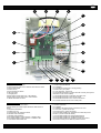
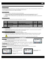
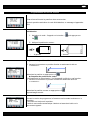
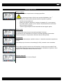
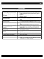
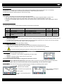
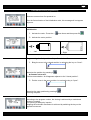
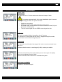
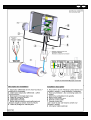
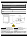
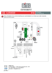
FR
MANUEL D’INSTALLATION COFFRET V2.1
GB
BOX V2.1 INSTALLATION INSTRUCTIONS
Photo non contractuelle
Juin 2010
Code : 17.1983.0001. Ind : 01
MANUEL D’INSTALLATION
5
6
7
FR
8
9
10
4
11
3
12
2
13
1
14
15
20
19
18
17
16
Bill of materials
1. Supply removable terminals
2. Fuse support for quick fuse 4 A/250Vac size ø5x20 or ø6x32
3. Varistor 420Vac/90J
4. Fuse ATO 15A
5. Power transformer 200VA
6. LED Light order
7. Led light power
8. Motor rotation order sense CW + LED indicator
9. Motor rotation order sense CCW + LED indicator
10. Brake removable connector
11. Button automatic/Manual
12. Automaton
13. Led indicator closed pool or closing pending
14. Brake card - pump drive
15. Lever terminals - pump drive
16. Removable terminals for contact switch NC normally close (Shunt
terminals if no NC contact cabled)
17. Removable terminals for salt water chlorinator drive
18. Removable terminals for key remote control
19. Removable terminals for rev. Counter card sensor
20. Screwed terminals for the motor cable power
Nomenclature
1. Bornier débrochable alimentation
2. Porte fusible pour fusible rapide 4A/250Vac taille ø5x20 ou
ø6x32
3. Varistance 420Vac/90J
4. Fusible ATO 15A
5. Transformateur de puissance 200VA.
6. Indicateur LED commande
7. Indicateur LED puissance
8. Commande rotation moteur sens SH + indicateur LED
9. Commande rotation moteur sens SIH + indicateur LED
10. Connecteur débrochable frein
11. Bouton auto/manu
12. Automate
13. Indicateur LED piscine fermé ou fermeture en cours
14. Carte frein – gestion de pompes
15. Bornier à levier : gestion de pompe
16. Bornier débrochable pour interrupteur à contact NC (bornes
shuntés si pas de contact NC câblé)
17. Bornier débrochable pour pilotage d’électrolyseur
18. Bornier débrochable pour la télécommande à clé
19. Bornier débrochable pour le capteur compte tours moteur.
20. Bornier à visser pour le câble de puissance moteur
2/12
MANUEL D’INSTALLATION
FR
INSTALLATION
Fixation du coffret.
Le coffret est destiné à être installé dans un local à l’abri des intempéries (ni exposé au soleil, ni exposé à la pluie). Il sera fixé sur un
mur vertical, à une hauteur de 1.5 m du sol mini, les câbles orientés vers le bas.
4 vis et 4 chevilles sont fournies avec le coffret pour la fixation.
Passage des câbles.
Tous les câbles connectés au coffret passeront par les presse-étoupes :
•
Le câble moteur passera par un presse-étoupe PG21 plastique. Sa section sera comprise entre 12 et 18 mm.
•
Les autres câbles passeront par des presse-étoupe PG13. Leur section sera comprise entre 6 et 12 mm.
•
Suivant les options installées (bouton stop, pilotage électrolyseur, coupure des pompes) d’autres presse-étoupes pourront
être installés.
Connexion aux bornes.
Les câbles seront connectés aux borniers suivant les prescriptions ci-dessous.
Rep
Désignation
1
20
16 à 19
Connecteur secteur
Connecteur moteur
Connecteur commande
Connecteur contrôle de pompe
(carte optionnelle)
14
Type
Débrochables, 0.6 Nm max, tournevis 3.5x0.5
1.5 Nm, tournevis 5x125
Débrochables, 0.6 Nm max, tournevis 3.5x0.5
Connecteur à levier, tournevis 3.5x0.5
Longueur
dénudée
7 mm
10 mm
7 mm
6 mm
Section max
2.5 mm²
16 mm²
2.5 mm²
2.5 mm²
Contacts électrolyseur rep 17
• Coupure de l’électrolyseur lorsque la piscine est fermée ou en cours de fermeture. La LED rep12 éclairée indique que la
piscine est fermée.
•
2 contacts NC NO disponibles pour piloter le relais de coupure de l’électrolyseur. Contacts secs, libres de tout potentiel.
•
Pouvoir de coupure maxi : 0.2A sous 125Vac et de 0.5A sous 30Vdc.
Carte frein et asservissement de pompe (rep14) (suivant option) :
• Renforcement du freinage des axes immergés profondément (H> 0.8m).
• Coupure des pompes lorsque la couverture est en mouvement. La LED éclairée indique que les pompes sont coupées.
• 2 contacts NC NO disponibles pour piloter le relais de coupure de la pompe. Contacts secs, libres de tout potentiel.
•
Ne pas piloter la pompe directement par l’intermédiaire de ces contacts (3A max sous 24Vdc max)
PROGRAMMATION
Mode manuel (bouton auto/manu rep11) :
•
Permet de faire tourner le moteur sans programmer les fins de courses
•
Permet de vérifier le fonctionnement du capteur compte tours du moteur
•
Permet de vérifier le câblage.
En sortie de ce mode manuel, la programmation des fins de courses de piscine est obligatoire.
Mode forçage (boutons SH et SIH Rep 8 et 9) : ces boutons permettent de manœuvrer la
couverture sans passer par l’automate.
Attention, les fins de courses seront déréglées après avoir actionné ces boutons.
Mode normal : Après la programmation des fins de courses (voir page suivante), les écrans suivant s‘affichent.
- Nombre de tours moteur (environ
0 lorsque la piscine est fermée)
- Courant consommé (10A max)
A l’arrêt, indication de la
version de soft
- Vitesse du moteur
- Etat : ouverture/fermeture/arrêt
du moteur
3/12
MANUEL D’INSTALLATION
FR
Programmation des fins de courses
Ecran d’accueil lors de la première mise sous tension.
Après la première activation du code d’initialisation, ce message n’apparaîtra
plus.
Initialisation :
1. Activation du code : 3 appuis sur la touche +
puis appuyer sur
OK
2. Indiquer la position du moteur :
-
: à gauche
+ : à droite
Programmer les positions limites « fermée » et « ouverte ».
1. Amener la couverture en position fermée en actionnant la clé sur
« fermeture » :
Mémoriser la position en appuyant sur A
.
Compteur de position mis à zéro.
Confirmation de la mémorisation : Un M apparaît à côté de « pos fermée ».
2. Amener la couverture en position ouverte en actionnant la clé sur
« ouverture » :
Mémoriser la position ouverte en appuyant sur B
Apprentissage terminé.
Suivant la version du programme, la fermeture est à contact maintenu ou à
impulsion.
L’ouverture est toujours à impulsion.
L’arrêt du mouvement automatique s’obtient en basculant la clé sur le
mouvement opposé.
4/12
MANUEL D’INSTALLATION
FR
Messages d’erreurs :
Erreur capteur
Le signal du capteur compte tours ne change pas d’état.
Le système se bloque. Seule une nouvelle initialisation (voir e
programmation du coffret) peut permettre de faire repartir le système.
-
Vérifier les branchements
Passer en manuel, actionner le moteur et regarder s’il y a mouvement
En mode manuel, vérifier qu’une tension est présente entre les fils bleu
(0V) et marron (+24Vdc).
Tester le signal capteur à l’aide du boitier de test signal capteur.
Erreur cycle
Le moteur est alimenté sans interruption pendant 5 minutes.
La manœuvre est suspendue et le moteur est arrêté pendant 20 secondes.
Aucune manœuvre ne pourra être effectuée durant cette période
Surintensité
Le disjoncteur électronique a arrêté le moteur intensité consommée supérieure
à 10A.
Cela indique que le moteur est surchargé (I>10A), contacter votre revendeur.
Sur le même cycle d’ouverture ou de fermeture, si cette erreur se produit 3 fois,
cet affichage clignotera avec l’écran ci-contre. Pour réinitialiser le système, il faut
appuyer sur l’interrupteur Marche-Arrêt du coffret.
Bouton stop actif
Absence de shunt sur le bornier Rep16
5/12
MANUEL D’INSTALLATION
FR
DEFAUTHEQUE
Problèmes
En phase d’initialisation, après avoir appuyé
sur A impossible d’amener la couverture en
position fermée
Solutions
-
LED commande éteinte
LED puissance éteinte
-
Ecran automate vide
-
Des indications en bas de l’écran
apparaissent.
Inversion des contacts ouverture – fermeture : vérifier le branchement
Mauvais branchement des contacts ouverture-fermeture : vérifier le
branchement
Position du moteur dans la piscine mal déclarée : finir l’initialisation en
appuyant successivement sur A et B, puis refaire +++ OK et
repositionner le moteur.
Débrancher le connecteur capteur, le connecteur boitier à clé, éteindre
le coffret et le rallumer afin de le réinitialiser. Un court circuit au niveau
du circuit de commande entraine la disjonction de celui ci. Vérifier le
câblage.
Vérifier le fusible 15A
Si nécessaire le changer par un fusible de même intensité. En mettre
un de taille supérieure risquerait d’endommager la carte.
Si la LED commande est éclairé, vérifier la connexion de l’automate à la
carte.
Vérifier la tension d’alimentation aux bornes + et – de l’automate
(24Vdc)
La petite clé présente en bas de l’écran est normale : verrouillage de
l’automate. En aucun cas, cela n’indique un disfonctionnement de
l’appareil. L’autre symbole tournant indique que l’automate est en
fonctionnement
Le coffret a pris la foudre : Contacter votre revendeur.
Prévoir d’installer un parafoudre
La pastille rouge est devenue noire et le
fusible 4A est HS
-
Le message surcharge s’affiche sans
interruption
-
Le moteur est surchargé (I>10A), revoir le montage, la taille du bassin
(6x12 max)
Vérifier qu’une quantité très importante de lames n’est pas pleine d’eau.
A l’écran apparait 1234 BCDE.
-
Absence du programme dans l’automate. Contacter votre revendeur
Le fusible 4A disjoncte continuellement
-
Contacter votre revendeur.
L’écran de l’automate n’est pas toujours
allumé
-
En mode manuel, la piscine s’ouvre au lieu de
se fermer
-
L’écran LCD s’allume 30 secondes chaque fois que l’une des touches
de la face avant est pressée
En mode manuel, la position du moteur dans la piscine n’est pas
déclarée, si il se trouve à gauche et que le câblage est correct, alors il y
a inversion des signaux ouverture et fermeture.
6/12
INSTALLATION INSTRUCTIONS
GB
INSTALLATION
Control box fixing
The control box is intended to be installed in a place away from bad weather (neither exposed to the sun, nor to the rain).
It will be fixed on a vertical wall, at 1.5m above ground minimum, cables will be ground oriented.
4 screws and 4 plugs are delivered with the control box for fixing.
Cables rooting
All the cables connected to the control box will go through cable glands:
• The motor cable will go through a PG21 plastic cable gland. Its section will be comprised between 12 and 18 mm
• The other cables will go through PG13 cable glands. Their section will be comprised between 6 and 12 mm
• According to the installed options (stop button, salt water chlorinator drive, pumps shut down) others cable glands could be
installed.
Connection to the terminals
The cables will be connected to the terminals according to the instructions hereunder.
Rep
1
20
16 à 19
14
Designation
Sector connector
Motor connector
Order connector
Pump control connector (card
in option)
Type
Removable, 0.6 Nm max, screwdriver 3.5x0.5
1.5 Nm, screwdriver 5x125
Removable, 0.6 Nm max, screwdriver 3.5x0.5
Lever connector, screwdriver 3.5x0.5
Unsheathed
length
7 mm
10 mm
7 mm
6 mm
Max section
2.5 mm²
16 mm²
2.5 mm²
2.5 mm²
Salt water chlorinator contacts rep 17
•
Salt water chlorinator shut down when the pool is closed or when the closing is pending. The LED rep12 indicates that the
pool cover is closed.
•
2 contacts NC NO available to drive the shut down relay of the salt water chlorinator. Dry contacts, free from any potential.
•
Max shut down power: 0.2A under 125Vac and 0.5A under 30Vdc.
Brake card and pump drive (rep14) (according to option):
• Brake reinforcing of deeply immersed axes (H>0.8m).
• Pump shut down when the cover is moving. The Lit up LED indicates that the pumps are off.
• 2 contacts NC NO available to drive the pump shut down relay. Dry contacts free from any potential.
•
Do not drive the pump directly through these contacts (3A max under 24Vdc max).
PROGRAMMATION
Manual mode (button automatic/manual rep11) :
•
Allowes to rotate the motor without programming the limit switch
sensors
•
Allowes to check the working of the motor rev.counter card
•
Allowes to check the cabling
Choosing the automatic mode obliges to program the limit switch sensors.
By-pass mode (button CW and CCW rep8 and 9): these buttons allow to move the cover without going through the automaton.
Be carefull, using this mode, will erase the limit switch sensors programming. You will need to do it again.
Standard mode: after the limit switch sensor programming (see next page), the following screens appear.
- Number of motor rev (near 0
when the cover is closed)
- Consumed current (10mA max)
When stopped, indicating the
software version
- Motor speed
- State : openning/closing/motor
stop
7/12
INSTALLATION INSTRUCTIONS
GB
Limit switch sensor programming
Welcome screen when first powered on
After the first activation of the initialization code, this message will not appear
anymore.
Initialisation :
1. Activate the code : Press the +
three times and then press OK
2. Indicate the motor position:
-
: Left
+ : Right
Programming the limit positions "open" and closed".
1. Bring the cover to the closed position in activating the key on "close" :
Memorize the position by pressing A
.
Counter set to zero.
Confirm memorization: An M appears adjacent to the "closed position".
2. Put the cover in the open position, by turning the key to "open":
Memorize the open position by pressing B
Learning complete.
According to the program version, the closing is achieved by a maintained
contact or impulse.
The opening is always by impulse.
Stopping the automatic movement is achieved by switching the key on the
opposite movement.
8/12
INSTALLATION INSTRUCTIONS
GB
Error messages :
Sensor error
The signal of the rev. Counter card sensor does not change of state.
The system squeezes itself. Only a new initialisation (see 1st control
box programming) can allow the system to restart.
-
Check the connections
Change to manual mode, and check if the cover moves
In manual mode, check that there is tension between the blue (0V) and
the brown (+24Vdc) wires
Test the sensor signal with the SIREM sensor signal test box
Cycle error
The motor is supplied without interruption during 5 minutes.
The manœuvre is interrupted and the motor is stopped during 20 seconds.
No manœuvre can be done during that period.
Overcurrent
The electronic circuit breaker has stopped the motor: current consumed more
than 10 A.
It indicates that the motor is overcharged (l>10A), contact your retailer.
If this error occurs three times on the same open or close cycle, the display
shown on the adjacent figure will blink.
Press the On-Off switch on the box to reinitialise the system
Stop button availability
No shunt on the terminal rep16
9/12
INSTALLATION INSTRUCTIONS
GB
TROUBLESHOOTING
Problems
Solutions
-
During the initialisation phase, after pushing
the A button, it is impossible for you to bring
the cover in the closed position.
-
Switched off order LED
Lit off power LED
-
Empty automaton screen
-
Indications appear at the bottom of the screen
Contacts for opening and closing might be inverted: check the
connections
Bad connection of the contacts opening and closing: check the
connection.
Position of the motor in the swimming pool badly registered: finish the
initilisation while pushing successively on A and B, then push +++OK
and bring the motor in position.
Unplug the sensor connector, the remote key connector switch off the
control box and switch it on again in order to reinitialise it. Shortcircuit
on the order circuit leads to a disjunction of it. Check the cables.
Check the fuse 15A
If necessary change it by a same intensity fuse. Replacing it by a
stronger fuse could damage the card.
If the other LED is lit on, check the connection from the automaton to
the card.
Check the supply tension to the terminals + and - of the automaton
(24Vdc).
The small key at the bottom of the screen is normal: means automaton
locked. In no way, this key indicates a dysfunction of the appareil. The
other turning symbol indicates that the automaton is working.
The red pastille has become black and the
fuse 4A is out of use
-
The control box was shot by the storm: contact your retailer.
Plan to install a lightening arrester.
Overload message appears without
interruption
-
The motor is overload (l>10A), check the installation again, and the size
of the swimming-pool (6x12 max)
Check if a large quantity of blades might be filled up with water.
1234 BCDE appears on the screen
-
No programme loaded in the automaton. Contact your retailer.
The 4A fuse breaks continually
-
Contact your retailer
The screen of the automaton is not lit
continually
-
In manual mode, the cover opens itself
instead of closing itself
-
The LCD screen switches on during 30 seconds each time that one of
the buttons of the front face is pushed.
In manual mode, the motor position in the swimming-pool is not
declared, if it is on the left side and that the cabling is OK, so there is an
inversion of the open and close signals.
10/12
INSTALLATION INSTRUCTIONS/MANUEL D’INSTALLATION
GB
FR
11/12
INSTALLATION INSTRUCTIONS/MANUEL D’INSTALLATION
GB
FR
Caractéristiques électriques / Electrical features
Tension d’entrée / Inlet voltage
Monophasé / Single phase, 220Vac/240Vac, 50/60Hz
Tension sortie puissance / Outlet power voltage
24Vdc ±20% sous 230 V / 24Vdc ±20% under 230 V
Tension sortie commande / Outlet order voltage
24V ±1%
Intensité maximale moteur / Maximum motor current
10A (limitation électronique / electronic limitation)
Intensité maximale absorbée (entrée) / Maximum inlet current
1.5A
Puissance max absorbée (moteur à 10A) / Maximum inlet power (motor at 10A)
290 W (1.5A, PF=0.85)
Puissance max absorbée en veille / Maximum inlet power in sleep mode
6 W (35mA, PF=0.7)
Limites d’utilisation / Using restriction
Température min d’utilisation / Min working temperature
Température max d’utilisation / Max working temperature
Température min de stockage / Min storage temperature
Température max de stockage / Max storage
temperature
Humidité relative / Relative humidity
-20°C
+50°C (en service intermittent 10% de 1 heure / in intermittant service class 10% of
1hour)
-40°C
+70°C
95% sans condensation / without capacitor
Tension min. d’alimentation / Min tension feeding
220 Vac
Tension max. d’alimentation / Max tension feeding
240 Vac
Encombrement / Bulk dimension
AVERTISSEMENT SECURITE
WARNING SECURITY
Raccordement électrique :
Les raccordements électriques doivent être réalisés par un électricien
qualifié. L’installation électrique devra être munie d’un système de
séparation multiple avec une ouverture des contacts d’au moins 3mm.
Le câble de raccordement réseau avec conducteur de protection
vert/jaune, doit avoir une section de 1mm² minimum.
Electrical connection:
Electric connections must be carried out by a qualified electrician. The
electrical motor must be wired by a professional according to the
Installation instructions of your local electricity company.
The mains connection cable including a yellow-and-green earth wire must
be of cross-section 1mm²
- Cet appareil n’est pas prévu pour être utilisé par des personnes (y
compris les enfants) dont les capacités physiques, sensorielles ou
mentales sont réduites, ou des personnes dénuées d’expérience ou
de connaissance, sauf si elles ont pu bénéficier, par l’intermédiaire
d’une personne responsable de leur sécurité, d’une surveillance ou
d’instructions préalables concernant l’utilisation de l’appareil.
This appliance is not intended for use by persons (including
children) with reduced physical, sensory or mental capabilities, or
lack of experience and knowledge, unless they have been given
supervision or instruction concerning use of the appliance by a
person responsible for their safety.
12/12