1
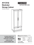
411985
Storage Cabinet
HomePlus Collection
NOTE: THIS INSTRUCTION BOOKLET CONTAINS
IMPORTANT SAFETY INFORMATION.
PLEASE CONTACT US
BEFORE RETURNING
YOUR UNIT TO THE STORE
1-800-523-3987
www.sauder.com
PLEASE READ AND KEEP FOR FUTURE REFERENCE.
English .................Page 1-12
Français ...........Pages 13-14
Made in the USA
Archbold, OH
Espanol..........Página 15-16
Lot #: 337660
04 / 07 / 11
Date Purchased: ____________________
TABLE OF CONTENTS
ASSEMBLY TOOLS REQUIRED
Part Identification .......................3
No. 2 Phillips Screwdriver
Hardware Identification .............4
Tip Shown Actual Size
Assembly Steps .................... 5-12
Français .............................. 13-14
Hammer
Espanol............................... 15-16
Safety ................................. 17-18
Warranty ...................................19
Page 2
www.sauder.com/services
411985
PART IDENTIFICATION: While not all parts are labeled, some of the parts will have a label or an
inked letter on the edge to help distinguish similar parts from each other. Use this PART IDENTIFICATION to
help identify similar parts.
A
RIGHT END
1
E
BACK
1
J
TOP MOLDING
1
B
LEFT END
1
F
DOOR
2
R
SIDE SKIRT
2
C
TOP
1
G
ADJUSTABLE SHELF
4
D
BOTTOM
1
H
FRONT SKIRT
1
E
C
J
G
B
A
G
F
G
G
F
D
R
H
R
411985
www.sauder.com/services
Page 3
HARDWARE IDENTIFICATION
I FRONT FOOT - 2
L TWIST-LOCK® FASTENER - 6
K REAR FOOT - 2
SAFETY
M HINGE - 6
N PULL - 2
Q METAL PIN - 16
S SLEEVE - 16
RUBBER
O BRACKET - 1
ADJUSTABLE
T GLIDE - 4
P DOOR STOP - 1
U PROPEL NUT - 4
V BLACK 1-7/8” FLAT HEAD SCREW - 5
W BLACK 7/8” MACHINE SCREW - 4
X BLACK 9/16” LARGE HEAD SCREW - 1
Y BLACK 9/16” WAFER HEAD SCREW - 4
Z BLACK 1/2” FLAT HEAD SCREW - 12
AA NAIL - 40
Screws are shown actual size. You may receive extra hardware with your unit.
Page 4
www.sauder.com/services
411985
S
p
te
Look for this icon. It means a video
assembly tip is available at:
www.sauder.com/services/tips
1
L
C
L
L
Assemble your unit on a carpeted floor or on the empty carton to avoid scratching your unit or the floor.
To begin assembly, push six SAUDER TWIST-LOCK® FASTENERS (L) into the large holes in the TOP (C).
NOTE: Do not tighten the TWIST-LOCK® FASTENERS at this time.
411985
www.sauder.com/services
Page 5
S
p
te
2
How to use the SAUDER TWIST-LOCK® FASTENER
1. Insert the dowel end of the FASTENER into the
hole of the adjoining part.
NOTE: The dowel end of the FASTENER must remain
fully inserted in the hole of the adjoining part while
locking the FASTENER.
2. Tighten the FASTENER with a Phillips screwdriver
as tight as possible.
Dowel end
Edge with
TWIST-LOCK®
FASTENERS
J
Fin
Wide edge
ish
Long finished edge
ed
C
B
A
Fasten the ENDS (A and B) to the TOP (C). Tighten four TWIST-LOCK® FASTENERS.
Fasten the TOP MOLDING (J) to the TOP (C). Tighten two TWIST-LOCK® FASTENERS.
Page 6
www.sauder.com/services
411985
S
Caution
Do not stand the unit upright without the
BACK fastened. The unit may collapse.
p
te
3
P
C
B
Rounded edge
A
Un
fini
she
d
D
V
BLACK 1-7/8” FLAT HEAD SCREW
(4 used in this step)
Push the DOOR STOP (P) into the hole in the TOP (C).
Fasten the BOTTOM (D) to the ENDS (A and B). Use four BLACK 1-7/8" FLAT HEAD SCREWS (V).
411985
www.sauder.com/services
Page 7
S
p
te
4
T
(4 used)
I
U
K
I
R
H
K
R
D
H
R
R
Y
BLACK 9/16” WAFER HEAD SCREW
(4 used in this step)
Slide the FEET (I and K) into the notches in the SKIRTS (H and R) as shown in the upper diagram.
Use a hammer to drive a PROPEL NUT (U) into the holes in the FEET (I and K). Now, turn an ADJUSTABLE GLIDE (T) into each
PROPEL NUT.
Fasten the SKIRTS (H and R) to the BOTTOM (D) as shown in the lower diagram. Use four BLACK 9/16" WAFER HEAD
SCREWS (Y) through the FEET and into the BOTTOM.
NOTE: To raise a corner of the unit, turn the ADJUSTABLE GLIDE counter-clockwise. To lower a corner, turn the ADJUSTABLE
GLIDE clockwise.
Page 8
www.sauder.com/services
411985
S
p
te
5
Caution
Do not stand the unit upright without the
BACK fastened. The unit may collapse.
AA
NAIL
(40 used in this step)
E
Carefully turn your unit over onto its front edges. Unfold the BACK (E) and lay it over your unit.
Make equal margins along all four edges of the BACK (E). Push on opposite corners of your unit if needed to make it “square”.
Fasten the BACK (E) to your unit using the NAILS (AA).
411985
www.sauder.com/services
Page 9
S
p
te
Mounting
screw
Z
6
BLACK 1/2” FLAT HEAD SCREW
(12 used for the HINGES)
Adjusting
screw
M
F
F
Adjusting
screw
M
Mounting
screw
N
B
F
W
BLACK 7/8” MACHINE SCREW
(4 used for the PULLS)
Fasten three HINGES (M) to each DOOR (F) as shown in the upper diagram.
Use twelve BLACK 1/2" FLAT HEAD SCREWS (Z).
Carefully stand your unit upright as shown in the lower diagram.
NOTE: You may need to loosen the mounting and adjusting screws to slide the hinge part way out of
the slot before fastening it to the END. Retighten the screw before you mount the HINGE to the END.
Fasten a DOOR (F) to the LEFT END (B). Use the screws in the HINGES. See the next step for adjustments.
Fasten a PULL (N) to the DOOR (F). Use two BLACK 7/8" MACHINE SCREWS (W).
Repeat this step for the other door.
Page 10
www.sauder.com/services
411985
S
p
te
7
Adjusting screw
(horizontal)
Mounting screw
(depth)
(vertical adjustment)
Refer to the enlarged diagram to identify the parts on the HINGES.
The DOORS may need some adjustments. Follow the text below to make needed adjustments.
DOOR ADJUSTMENTS:
To adjust the DOORS from side to side (horizontal), loosen the mounting screw several turns, then turn the adjusting screw in or out.
Tighten the mounting screw after making adjustments.
To adjust the DOORS up and down (vertical), loosen both vertical adjustment screws. Move the DOORS up or down to the desired
location. Tighten the screws after making adjustments.
To adjust the DOORS in or out (depth), loosen the mounting screw one turn and move the DOORS in or out, as needed. Tighten the
mounting screw after making adjustments.
411985
www.sauder.com/services
Page 11
S
p
te
8
V
BLACK 1-7/8” FLAT HEAD SCREW
(1 used into a stud in your wall)
O
No load
X
BLACK 9/16” LARGE HEAD SCREW
(1 used for the SAFETY BRACKET)
G
25 lbs.
G
25 lbs.
B
Q
A
G
25 lbs.
(16 used)
S
G
25 lbs.
50 lbs.
Place your unit into its final position against a wall.
Fasten the SAFETY BRACKET (O) for added stability. Use a BLACK 9/16” LARGE HEAD SCREW (X) into the top of the unit and
a BLACK 1-7/8” FLAT HEAD SCREW (V) into a stud in your wall.
Push the RUBBER SLEEVES (S) over the METAL PINS (Q). Insert the METAL PINS into the hole locations of your choice in the
ENDS (A and B). Set the ADJUSTABLE SHELVES (G) onto the METAL PINS.
NOTE: Please read the back pages of the instruction booklet for important safety information.
This completes assembly. Clean with your favorite furniture polish or a damp cloth. Wipe dry.
Page 12
www.sauder.com/services
411985
411985
Utilisez les instructions d’assemblage en français avec
les schémas étape par étape du manuel d’instruction
en anglais. Chaque étape en français correspond à la
même étape en anglais. La pièce devant être attachée
à l’élément est représentée en gris sur les schémas de
chaque étape pour plus de précision. Comparer la “Liste
de pièces” ci-dessous avec la “PART IDENTIFICATION”
du manuel en anglais pour vous familiariser avec les
pièces avant l’assemblage.
REMARQUE : CE MANUEL D’INSTRUCTIONS
CONTIENT D’IMPORTANTES INFORMATIONS
RELATIVES À LA SÉCURITÉ. À LIRE ET CONSERVER
POUR TOUTE RÉFÉRENCE FUTURE.
Meuble de rangement
NOUS SOMMES LA POUR VOUS AIDER!
Nous faisons de notre mieux pour nous assurer que
votre meuble arrive dans d’excellentes conditions. Nos
représentants du service Clientèle sont aimables et prêts
à vous aider au cas où une pièce aurait été endommagée
ou manquerait (ou si vous aviez besoin d’aide pour
l’assemblage). NE RAMENEZ PAS LE MEUBLE AU
MAGASIN. Au Canada, composez ce numéro d’appel gratuit:
1-800-523-3987
Du lundi au vendredi, de 9 heures du matin à
5:30 heures du soir (horaire Côte Est)
(sauf jours fériés)
Si une pièce a besoin d’être remplacée, la pièce de
remplacement sera envoyée dans les 48 heures. (Sauf
week-ends et jours fériés)
LISTE DE PIECES
REFERENCE DESCRIPTION
QUANTITE
LISTE DE PIECES
REFERENCE DESCRIPTION
QUANTITE
A
EXTRÉMITÉ DROITE ......................1
I
PIED AVANT ....................................2
B
EXTRÉMITÉ GAUCHE ....................1
K
PIED ARRIÈRE ................................2
C
DESSUS ..........................................1
L
FIXATION TWIST–LOCK® ..............6
D
DESSOUS .......................................1
M
CHARNIÈRE ....................................6
E
ARRIÈRE .........................................1
N
POIGNÉE .........................................2
F
PORTE .............................................2
O
CONSOLE DE SÉCURITÉ ..............1
G
TABLETTE RÉGLABLE ...................4
P
ARRÊT DE PORTE..........................1
H
PLINTHE AVANT..............................1
Q
GOUPILLE EN MÉTAL ..................16
J
MOULURE DE DESSUS .................1
S
MANCHON EN CAOUTCHOUC ....16
R
PLINTHE LATÉRALE .......................2
T
PATIN RÉGLABLE ...........................4
U
TOURILLON.....................................4
V
VIS NOIRE TÊTE PLATE 48 mm.....5
W
VIS ARGENTÉE TÊTE
PLATE 28 mm ..................................4
X
VIS NOIRE TÊTE LARGE 14 mm....1
Y
VIS NOIRE TÊTE MINCE 14 mm ....4
Z
VIS NOIRE TÊTE PLATE 13 mm...12
AA
CLOU .............................................52
A l’usage exclusif du
Canada Noter la date
d’achat de cet élément
et conserver le livret
pour future référence.
Pour contacter Sauder
en ce qui concerne cet
élément, faire référence
au numéro de lot et
numéro de modèle en
appelant notre numéro
sans frais.
Lot nº : ____________
Date de
l’achat: ____________
411985
www.sauder.com/services
Page 13
ETAPE 1
ETAPE 6
Assembler l’élément sur un sol à moquette ou sur le
carton vide pour éviter d’endommager l’élément ou le sol.
Pour commencer l'assemblage, enfoncer six
FIXATIONS TWIST-LOCK® SAUDER (L) dans les gros
trous dans le DESSUS (C).
REMARQUE : Ne pas serrer les FIXATIONS TWISTLOCK® à ce stade de l'assemblage.
Fixer les CHARNIÈRES (M) aux PORTES (F). Utiliser
douze VIS NOIRES TÊTE PLATE 13 mm (Z).
Relever, avec précaution, l’élément dans sa position
verticale.
Fixer une PORTE (F) à l'EXTRÉMITÉ GAUCHE (B).
Utiliser les vis fournies avec les CHARNIÈRES.
REMARQUE : Il est peut-être nécessaire de desserrer
la vis de fixation pour le glisser partiellement hors de la
fente. Resserrer la vis avant de monter la CHARNIÈRE
à l’EXTRÉMITÉ.
Fixer une POIGNÉE (N) à la PORTE (F). Utiliser deux
VIS ARGENTÉES TÊTE PLATE 28 mm (W).
Répéter cette étape pour l'autre porte.
ETAPE 2
Utilisation de la FIXATION TWIST-LOCK® SAUDER
(Consulter le schéma agrandi.)
1. Insérer l’extrémité filetée de la FIXATION dans le trou
de la pièce attenante.
REMARQUE : L’extrémité filetée de la FIXATION doit
rester complètement insérée dans le trou de la pièce
attenante lorsque l’on bloque la FIXATION.
2. Bien serrer la FIXATION à l’aide d’un tournevis Phillips.
Fixer les EXTRÉMITÉS (A et B) au DESSUS (C). Serrer
quatre FIXATIONS TWIST-LOCK®.
Fixer la MOULURE DE DESSUS (J) au DESSUS (C).
Serrer deux FIXATIONS TWIST-LOCK®.
ETAPE 3
Enfoncer l'ARRÊT DE PORTE (P) dans le trou du DESSUS (C).
Fixer le DESSOUS (D) aux EXTRÉMITÉS (A et B).
Utiliser quatre VIS NOIRES TÊTE PLATE 48 mm (V).
ETAPE 4
Faire glisser les PIEDS (I et K) dans les crans des
PLINTHES (H et R).
À l'aide d'un marteau, enfoncer un TOURILLON (U) à
travers les trous dans les PIEDS (I et K). Maintenant,
faire tourner un PATIN RÉGLABLE (T) dans chaque
TOURILLON comme l'indique le schéma du haut.
Fixer les PLINTHES (H et R) au DESSOUS (D). Utiliser quatre
VIS NOIRES TÊTE MINCE 14 mm (Y) à travers les PIEDS et
dans le DESSOUS comme l'indique le schéma du bas.
REMARQUE : Pour soulever un coin de l'élément, faire
tourner le PATIN RÉGLABLE dans le sens contraire
des aiguilles d'une montre. Pour baisser un coin, faire
tourner le PATIN RÉGLABLE dans le sens des aiguilles
d'une montre.
ETAPE 5
Avec précaution, retourner l’élément sur ses chants
avant. Déplier l’ARRIÈRE (E) et le placer sur l’élément.
Veiller à avoir des marges égales le long des quatre chants
de l’ARRIÈRE (E). Si besoin est, enfoncer sur les coins
opposés de l’élément pour s’assurer d’être « d’équerre ».
Fixer l’ARRIÈRE (E) à l’élément en utilisant les CLOUS (AA).
Page 14
ETAPE 7
Consulter le schéma agrandi pour identifier les pièces
des CHARNIÈRES.
Il faut peut-être ajuster les PORTES. Suivre les
indications ci-dessous pour ajuster.
RÉGLAGES DE PORTES:
Pour ajuster les PORTES latéralement
(horizontalement), desserrer la vis de montage quelques
tours et tourner la vis de réglage vers l’intérieur ou vers
l’extérieur. Serrer la vis de montage après avoir ajusté.
Pour ajuster les PORTES de haut en bas
(verticalement), desserrer les deux vis de réglage.
Déplacer les PORTES verticalement à l’emplacement
désiré. Serrer les vis après avoir ajusté.
Pour ajuster les PORTES vers l’intérieur où vers
l’extérieur (profondeur), desserrer la vis de montage
un tour et déplacer les PORTES vers l’intérieur ou vers
l’extérieur. Serrer la vis de montage après avoir ajusté.
ETAPE 8
Placer l’unité à sa place finale, contre un mur.
Il est recommandé d'utiliser la CONSOLE DE
SÉCURITÉ (O) pour renforcer la stabilité. Utiliser une
VIS NOIRE TÊTE LARGE 14 mm (X) dans le haut de
l'élément et une VIS NOIRE TÊTE PLATE 48 mm (V)
dans un montant du mur.
Enfoncer les MANCHONS EN CAOUTCHOUC (S)
sur les GOUPILLES EN MÉTAL (Q). Insérer les
GOUPILLES EN MÉTAL dans les trous choisis dans
les EXTRÉMITÉS (A et B). Poser les TABLETTES
RÉGLABLES (G) sur les GOUPILLES EN MÉTAL.
REMARQUE : Prière de lire attentivement les
importantes informations concernant la sécurité
qui figurent sur la couverture arrière du manuel
d'instructions.
Ceci complète l'assemblage. Pour nettoyer, utiliser
l'encaustique pour meubles préférée ou un chiffon
humide. Essuyer.
www.sauder.com/services
411985
Armario de
Almacenamiento
411985
Use estas instrucciones de ensamblaje en español junto
con las figuras paso-a-paso provistas en el folleto inglés.
Cada paso en español corresponde al mismo paso en
inglés. Se destacan las figuras de cada paso con una
tonalidad oscura para mostrar precisamente cual parte se
debe montar a la unidad. Compare la “Lista de Part” abajo
con la “Part Identification” en el folleto en inglés para
familiarizarse con Las partes de ensamblaje.
NOTA: ESTE FOLLETO DE INSTRUCCIONES
CONTIENE INFORMACIÓN IMPORTANTE SOBRE LA
SEGURIDAD. POR FAVOR LEA Y GUÁRDELO PARA
REFERENCIA EN EL FUTURO.
ESTAMOS AQUI PARA AYUDAR!
Tratamos de asegurar que su mueble llega en condición
excelente. Nuestros representantes de Servicio al Cliente
son amables y listos para ayudarle con servicio rápido
y eficiente si una parte está defectuosa o ausente (o si
necesita ayuda con el ensamblaje). NO DEVUELVA LA
UNIDAD A LA TIENDA. Llame este número sin cargo:
1-800-523-3987
Lunes a viernes, 9:00 a.m. - 5:30 p.m.
Hora oficial del Este
(excepto días festivos)
Si requiere un repuesto de una parte, será enviado dentro
de 48 horas (excepto los fines de semana y días festivos)
LISTA DE PARTES
ITEM
DESCRIPCIÓN
CANTIDAD
LISTA DE PARTES
ITEM
DESCRIPCIÓN
CANTIDAD
A
EXTREMO DERECHO ....................1
I
PATA DELANTERA ..........................2
B
EXTREMO IZQUIERDO ..................1
K
PATA POSTERIOR ..........................2
C
PANEL SUPERIOR ..........................1
L
SUJETADOR TWIST–LOCK® .........6
D
FONDO ............................................1
M
BISAGRA .........................................6
E
DORSO ............................................1
N
TIRADOR .........................................2
F
PUERTA ...........................................2
O
MÉNSULA DE SEGURIDAD ...........1
G
ESTANTE AJUSTABLE....................4
P
TOPE DE PUERTA ..........................1
H
FALDÓN DELANTERO ....................1
Q
ESPIGA DE METAL .......................16
J
MOLDURA DE PANEL SUPERIOR .1
S
MANGUITO DE GOMA ..................16
R
FALDÓN LATERAL ..........................2
T
DESLIZAMIENTO AJUSTABLE .......4
U
TUERCA ..........................................4
V
TORNILLO NEGRO DE CABEZA
PERDIDA de 48 mm ........................5
W
TORNILLO PLATEADO DE
CABEZA PERDIDA de 28 mm .........4
X
TORNILLO NEGRO DE CABEZA
GRANDE de 14 mm .........................1
Y
TORNILLO NEGRO DE CABEZA
DE DISCO de 14 mm .......................4
Z
TORNILLO NEGRO DE CABEZA
PERDIDA de 13 mm ......................12
AA
CLAVO ...........................................52
Anote la fecha de
comprar esta unidad y
guarde el folleto para
su referencia futura.
Si necesita ponerse
en contacto con
Sauder en cuanto a
esta unidad, refiérase
al número de lote y
al número de modelo
cuando llame a nuestro
número gratis.
No. Lote: ___________
Fecha
de compra: _________
411985
www.sauder.com/services
Page 15
PASO 1
PASO 6
Ensamble la unidad sobre un piso alfombrado o sobre
el cartón vacío para evitar rayar la unidad o el piso.
Para comenzar el ensamblaje, empuje seis
SUJETADORES TWIST-LOCK® SAUDER (L) dentro de
los agujeros grandes del PANEL SUPERIOR (C).
NOTA: No apriete los SUJETADORES TWIST-LOCK® por ahora.
Fije las BISAGRAS (M) a las PUERTAS (F). Utilice
doce TORNILLOS NEGROS DE CABEZA PERDIDA de
13 mm (Z).
Cuidadosamente ponga la unidad en posición vertical.
Fije una PUERTA (F) al EXTREMO IZQUIERDO (B).
Utilice los tornillos provistos de las BISAGRAS.
NOTA: Puede ser necesario aflojar el tornillo de montaje
para deslizar parcialmente fuera de la ranura. Vuelva
a apretar el tornillo antes de montar la BISAGRA al
EXTREMO.
Fije un TIRADOR (N) a la PUERTA (F). Utilice dos
TORNILLOS PLATEADOS DE CABEZA PERDIDA de
28 mm (W).
Repita este paso para la otra puerta.
PASO 2
Cómo utilizar el SUJETADOR TWIST-LOCK® SAUDER
(Refiérase al diagrama ampliado.)
1. Inserte el extremo con cabilla del SUJETADOR
dentro del agujero de la parte adjunta.
NOTA: El extremo con cabilla del SUJETADOR debe
quedarse completamente insertado en el agujero de la
parte adjunta cuando se enclava el SUJETADOR.
2. Apriete el SUJETADOR lo más apretado posible con
un destornillador Phillips (cruz).
Fije los EXTREMOS (A y B) al PANEL SUPERIOR (C).
Apriete cuatro SUJETADORES TWIST-LOCK®.
Fije la MOLDURA DE PANEL SUPERIOR (J) al PANEL
SUPERIOR (C). Apriete dos SUJETADORES TWIST-LOCK®.
PASO 3
Empuje el TOPE DE PUERTA (P) dentro del agujero del
PANEL SUPERIOR (C).
Fije el FONDO (D) a los EXTREMOS (A y B). Utilice cuatro
TORNILLOS NEGROS DE CABEZA PERDIDA de 48 mm (V).
PASO 4
Deslice las PATAS (I y K) dentro de las muescas de los
FALDONES (H y R).
Utilice un martillo para golpear una TUERCA (U) a
través de los agujeros de las PATAS (I y K). Ahora, gire
un DESLIZAMIENTO AJUSTABLE (T) dentro de cada
TUERCA como se muestra en el diagrama superior.
Fije los FALDONES (H y R) al FONDO (D). Utilice
cuatro TORNILLOS NEGROS DE CABEZA DE DISCO
de 14 mm (Y) a través de las PATAS y dentro del
FONDO como se muestra en el diagrama inferior.
NOTA: Para levantar una esquina de la unidad, gire
el DESLIZAMIENTO AJUSTABLE hacia la izquierda.
Para bajar una esquina, gire el DESLIZAMIENTO
AJUSTABLE hacia la derecha
PASO 5
Cuidadosamente voltee la unidad para que repose
sobre los bordes delanteros. Desdoble el DORSO (E) y
colóquelo sobre la unidad.
Fije el DORSO (E) de manera que los márgenes son
iguales a lo largo de los cuatro bordes. Empuje sobre
las esquinas opuestas de la unidad si es requerido para
hacerla “cuadrada.”
Fije el DORSO (E) a la unidad utilizando los CLAVOS (AA).
Page 16
PASO 7
Consulte el diagrama ampliado para identificar las
piezas de las BISAGRAS.
Las PUERTAS pueden requerir de ajustes. Siga las
instrucciones abajo para hacer los ajustes.
AJUSTE LAS PUERTAS:
Para ajustar las PUERTAS de un lado al otro
(horizontalmente), afloje el tornillo de montaje varias
vueltas y gire el tornillo de ajuste hacia el interior o
hacia el exterior. Apriete el tornillo de montaje después
de hacer los ajustes.
Para ajustar las PUERTAS hacia arriba o hacia abajo
(vertical), afloje los dos tornillos de ajuste. Mueva las
PUERTAS hacia arriba o hacia abajo a la ubicación
deseada. Apriete los tornillos después de hacer los
ajustes.
Para ajustar las PUERTAS hacia atrás o hacia adelante
(profundidad), afloje el tornillo de montaje una vuelta y
mueva las PUERTAS hacia el interior o hacia el exterior
según sea necesario. Apriete el tornillo de montaje
después de hacer los ajustes.
PASO 8
Coloque su unidad en su posición final contra una pared.
Se recomienda que utilice la MÉNSULA DE
SEGURIDAD (O) para aumentar la estabilidad. Utilice
un TORNILLO NEGRO DE CABEZA GRANDE de
14 mm (X) a través de la parte superior de la unidad y
un TORNILLO NEGRO DE CABEZA PERDIDA de
48 mm (V) dentro de un montante de la pared.
Empuje los MANGUITOS DE GOMA (S) sobre las
ESPIGAS DE METAL (Q). Inserte las ESPIGAS DE
METAL dentro de los agujeros al nivel preferido de
los EXTREMOS (A y B). Coloque los ESTANTES
AJUSTABLES (G) sobre las ESPIGAS DE METAL.
NOTA: Por favor lea las páginas finales del folleto de
instrucciones para información importante sobre la
seguridad.
Esto completa el ensamblaje. Limpie con su pulimento
para muebles preferido o un paño húmedo. Seque con
un paño.
www.sauder.com/services
411985
WARNING
Please use your furniture correctly and safely. Improper use can cause safety hazards,
or damage to your furniture or household items. Carefully read the following chart.
Look out for:
What can happen:
How to avoid the problem:
• Overloaded drawers and shelves.
• Risk of injury.
• Top-heavy furniture can tip over.
• Overloaded drawers or shelves can
break.
• Never exceed the weight limits shown in
the instructions.
• Work from bottom to top when loading
shelves and drawers. Place the heavier items
on the lower shelves or in lower drawers.
• Children climbing on furniture.
• A child may try to reach a toy or other
object by climbing on furniture.
• Risk of injury or death
• A child climbing on a piece of furniture
can make it top-heavy and cause it to tip
over.
• Never allow children to climb on or play
with furniture. Do not place toys, food,
etc. on the top shelves or upper drawers.
• Use the supplied safety bracket for added
stability.
• Placing TVs on furniture items that are
not designed to support a television is
hazardous.
• Risk of injury or death. TVs can be
very heavy. Plus the weight and location
of the picture tube tends to make TVs
unbalanced and prone to tipping forward.
• This product is not designed to support a
television.
• Improperly moving furniture that is not
designed and equipped with casters.
• Furniture can tip over or break if
improperly moved.
• Physical injury. Furniture can be very
heavy.
• Unload drawers and shelves from top to
bottom before moving the furniture.
• Do not push furniture, especially on a
carpeted floor. Have a friend help you lift
the unit and set it in place.
• This unit must be positioned against a
wall.
AVERTISSEMENT
Prière d’utiliser le mobilier à bon escient et avec prudence. Une mauvaise utilisation peut être à l’origine de risques
d’accident ou peut endommager le mobilier et les articles ménagers. Lire attentivement le tableau suivant.
À surveiller :
Danger éventuel :
Solution :
• Tiroirs de commodes
surchargés.
• Risque de blessure.
• Du mobilier mal équilibré risque de
se renverser.
• Des tiroirs surchargés peuvent casser.
• Ne jamais excéder les limites de poids
indiquées dans les instructions.
• Commencer a charger les tablettes et
tiroirs à partir du bas et finir au haut.
Placer les objets les plus lourds dans les
tiroirs inférieurs.
• Les enfants qui grimpent sur
le mobilier.
• Un enfant peut grimper sur le
mobilier pour essayer d’attraper
un jouet ou tout autre objet.
• Risque de blessures graves,
voire mortelles.
• Un enfant qui grimpe sur un meuble
risque de déséquilibrer ce dernier et de
le faire tomber.
• Ne jamais laisser les enfants grimper sur
le mobilier ou jouer avec. Ne pas placer
de jouets, d’aliments, etc. sur le haut des
éléments.
• Utiliser la console de sécurité fournie
pour renforcer la stabilité.
• Il est dangereux de placer des
téléviseurs sur des meubles qui
ne sont pas prévus à cet effet.
• Risque de blessures graves, voire
mortelles. Les téléviseurs peuvent être
particulièrement lourds. De plus, le
poids et l’emplacement du tube image
ont tendance à rendre les téléviseurs
instables et enclins à tomber
vers l’avant.
• Ce produit n’est pas destiné à supporter
un téléviseur.
• Déplacement inadéquat d’un
mobilier qui n’est pas conçu
pour avoir des roulettes et n’en
est pas équipé.
• Le mobilier risque de se renverser
ou de casser en cas de déplacement
inadéquat.
• Blessure physique. Le mobilier peut
être très lourd.
• Décharger les tiroirs en commençant par
celui du
haut avant de déplacer la commode.
• Ne pas pousser le mobilier, surtout sur la
moquette. Se faire aider par une autre
personne pour soulever la commode et la
mettre en place.
• Cette unité doit être placée contre un
mur.
411985
www.sauder.com/services
Page 17
ADVERTENCIA
Por favor use el mobiliario correcta y seguramente. El mal uso puede causar riesgos de seguridad
o daño a las unidades o artículos domésticos. Cuidadosamente lea la tabla a continuación.
Esté alerto de:
Puede ocurrir:
Evitar el problema:
• El sobrecargo de cajones de
cómoda
• Un riesgo de lesiones.
• La caída de mobiliario inestable.
• La rotura de cajones sobrecargados.
• Nunca exceder los límites de peso
indicados en las instrucciones.
• Para cargar los estantes y cajones,
comience al fondo y termine en la parte
superior. Coloque los artículos más
pesados en los cajones inferiores.
• Los niños subiendo el mobiliario.
• Un niño que intenta a alcanzar
un juego u otro objeto subiendo
el mobiliario.
• Un riesgo de lesiones o la muerte.
• Que un niño subiendo el mobiliario
cause la inestabilidad y resultará la
caída de la unidad.
• Nunca permita que los niños suban o
jueguen sobre el mobiliario. No coloque
los juegos, alimentos, etc. encima de las
unidades.
• Utilice la ménsula de seguridad
proporcionada para añadir más estabilidad.
• La colocación de televisores
sobre unidades no intencionadas
para su soporte es peligrosa.
• Un riesgo de lesiones o la muerte.
Los televisores pueden ser muy
pesados. Además, el peso y la
ubicación del tubo de imagen tienden
a causar la inestabilidad de
televisores y propensa a inclinarse
hacia adelante.
• Este producto no está diseñado para
soportar un televisor.
• Mover incorrectamente el
mobiliario que no está diseñado
y provisto con ruedecitas.
• La inclinación o rotura de
mobiliario si se mueve
inapropiadamente.
• Lesión física. El mobiliario puede
ser muy pesado.
• Descargue los cajones desde arriba hacia
abajo antes de mover la cómoda.
• No empuje la unidad, especialmente
sobre un piso alfombrado. Pide a otra
persona su ayuda en levantar la cómoda y
colocarla en lugar.
• Esta unidad debe ser colocada contra una
pared.
Page 18
www.sauder.com/services
411985
5-YEAR LIMITED WARRANTY
1. Sauder Woodworking Co. (Sauder®) provides limited warranty coverage to
the original purchaser of this product for a period of five years from the date
of purchase against defects in materials or workmanship of Sauder furniture
components. As used in this Warranty, “defect” means imperfections in
components which substantially impair the utility of the product. This Warranty
gives you specific legal rights, and you may also have other rights which vary
from state to state.
2. There is no warranty coverage for defects or conditions that result from the
failure to follow product assembly instructions, information or warnings, misuse
or abuse, intentional damage, fire, flood, alteration or modification of the product,
or use of the product in a manner inconsistent with its intended use, nor any
condition resulting from incorrect or inadequate maintenance, cleaning, or care.
There is also no warranty coverage for rented products or any products purchased
“used” or “as is”, at a distress or going-out-of business sale, or from a liquidator.
3. As the exclusive remedy under this Warranty, Sauder will (at its sole
option) repair or replace any defective furniture component. Sauder may
require independent confirmation of the claimed defect and proof of purchase.
Replacement parts will be warranted for only the remaining period of the original
Warranty. SAUDER SHALL HAVE NO LIABILITY for ANY INCIDENTAL
OR CONSEQUENTIAL DAMAGES OF ANY KIND and all such damages
are EXCLUDED FROM THIS WARRANTY, such as loss of use, disassembly,
transportation, labor or damage to property on or near the product. Some states do
not allow the exclusion or limitation of incidental or consequential damages, so
the above limitation or exclusion may not apply to you.
4. This Warranty applies only to warranted defects that first arise and are reported
to Sauder within the warranty coverage period. The Warranty cannot be transferred
to subsequent owners or users of the product, and it shall be immediately void in
the event the product is resold, transferred, leased or rented to any third party or
person other than the original purchaser.
5. THERE ARE NO OTHER WARRANTIES APPLICABLE TO THIS
PRODUCT. Under the laws of certain states, there may be no implied warranties
from Sauder and all implied warranties, INCLUDING ANY IMPLIED
WARRANTY OF MERCHANTABILITY OR FITNESS FOR A PARTICULAR
PURPOSE are disclaimed where allowed by law. TO THE EXTENT ANY
IMPLIED WARRANTIES ARE APPLICABLE, ANY IMPLIED WARRANTIES,
INCLUDING ANY IMPLIED WARRANTY OF MERCHANTABILITY OR
FITNESS FOR A PARTICULAR PURPOSE, ARE LIMITED IN DURATION
TO THE DURATION OF THIS EXPRESS WARRANTY or the minimum period
allowed by law, whichever is shorter. Some states do not allow limitations on how
long an implied Warranty lasts, so the above limitation may not apply to you.
6. For Warranty inquiries or claims, please visit our website www.sauder.com.
You can also contact Sauder at 1-800-523-3987. Sauder may require Warranty
claims to be submitted in writing to Sauder Woodworking Co., 502 Middle Street,
Archbold, OH 43502 USA. Please include your sales receipt or other proof of
purchase and a specific description of the product defect.
GARANTIE LIMITÉE DE 5 ANS
1. Sauder Woodworking Co. (Sauder®) offre une couverture de garantie
limitée à l’acheteur initial du présent produit pendant une période de cinq ans
à compter de la date d’achat contre tout défaut de matériaux ou de fabrication
des composantes de mobilier Sauder. Le mot « défaut », tel qu’il est utilisé sous
les termes de la présente garantie, comprend les imperfections des pièces qui
empêchent substantiellement l’utilisation du produit. La présente garantie vous
donne des droits légaux spécifiques et il est possible que vous ayez des droits
supplémentaires variant d’État en État ou de province en province.
2. La présente garantie ne saurait couvrir les défauts ou conditions qui surviendraient
à la suite du non respect des instructions, informations ou mises en garde de
montage, d’une mauvaise utilisation ou d’un abus, d’un dommage intentionnel,
d’un incendie, d’une inondation, d’une altération ou modification du produit, d’une
utilisation du produit allant à l’encontre de son usage prévu, ni aucune condition
résultant d’une maintenance, d’un nettoyage ou d’un entretien inappropriés ou
inadéquats. De plus, il n’existe aucune garantie pour les produits loués ou tous
les produits achetés « d’occasion » ou « en l’état », dans le cadre d’une vente aux
enchères ou de solde pour cessation de commerce, ou auprès d’un liquidateur.
3. En tant que recours exclusif en vertu de la présente garantie, Sauder réparera
ou remplacera (sur sa seule décision) toute composante de mobilier défectueuse.
Sauder peut exiger une confirmation indépendante du défaut revendiqué ainsi
qu’une preuve d’achat. Les pièces de rechange seront garanties uniquement
pendant la période restante de la garantie originale. SAUDER NE SERA EN
AUCUN CAS RESPONSABLE de TOUT DOMMAGE ACCESSOIRE OU
CONSÉCUTIF DE TOUTE SORTE et lesdits dommages sont EXCLUS DE LA
PRÉSENTE GARANTIE, à savoir perte d’utilisation, démontage, transport, main
d’ceuvre ou dommages matériels sur ou à proximité du produit. Certains États
ou provinces ne permettant pas l’exclusion ou la limite aux responsabilités pour
dommages accidentels ou consécutifs, la limite ou l’exclusion ci-dessus peut ne
pas être applicable.
4. La présente garantie ne s’applique qu’aux défauts garantis qui se produisent
pour la première fois et qui sont signalés à Sauder dans les limites de ouverture
de la garantie. La garantie ne peut pas être transférée à des propriétaires ou
utilisateurs subséquents du produit, et sera immédiatement invalidée dans le cas
où le produit est revendu, transféré, loué sous bail ou loué à une tierce partie ou
personne autre que l’acheteur original.
5. IL N’EXISTE AUCUNE AUTRE GARANTIE EN VIGUEUR POUR LE
PRÉSENT PRODUIT. En vertu des lois de certains États ou provinces, il ne peut y
avoir de garanties implicites de la part de Sauder et toutes les garanties implicites,
Y COMPRIS TOUTE GARANTIE IMPLICITE DE COMMERCIABILITÉ
OU D’ADAPTATION À UN USAGE PARTICULIER sont déclinées partout où
la loi l’autorise. DANS LA MESURE OÙ TOUTE GARANTIE IMPLICITE
EST APPLICABLE, TOUTE GARANTIE IMPLICITE, Y COMPRIS TOUTE
GARANTIE DE COMMERCIABILITÉ OU D’ADAPTATION À UN USAGE
PARTICULIER, EST LIMITÉE À LA DURÉE DE LA PRÉSENTE GARANTIE
EXPRESSE ou à la période minimum autorisée par la loi, la période la plus courte
étant retenue. Certains États ne permettant pas que des limites soient imposées quant à
la durée d’une garantie implicite, la limite ci-dessus peut donc ne pas être applicable.
6. Pour toute question concernant la garantie ou toute demande de réclamation,
consulter le site Web www.sauder.com. Il est également possible de contacter
Sauder en composant le 1-800-523-3987. Sauder peut exiger de soumettre les
demandes de réclamation sous garantie par écrit à Sauder Woodworking Co., 502
Middle Street, Archbold, OH 43502 USA. Veuillez joindre votre ticket de caisse ou
toute autre preuve d’achat ainsi qu’une description spécifique du défaut de produit.
GARANTÍA LIMITADA DE 5 AÑOS
1. Sauder Woodworking Co. (Sauder®) provee cobertura de garantía limitada
al comprador original de este producto por un período de cinco años, a partir de
la fecha de compra, contra defectos en los materiales o de mano de obra en los
componentes de muebles Sauder. Como es utilizado en esta Garantía, “defecto”
significa imperfecciones en los componentes que de manera fundamental afecta
la utilidad del producto. Esta Garantía le permite a usted ciertos derechos legales,
y usted también podría poseer otros derechos adicionales, los cuales varían de
estado a estado.
2. No hay cobertura de garantía para defectos o estados que resulten del
incumplimiento en seguir las instrucciones, la información o las advertencias
sobre el ensamblaje del producto; del uso incorrecto o maltrato, del daño
intencional, incendio, inundación, cambio o modificación del producto; o de
la utilización del producto de manera contradictoria con el uso para el cual fue
fabricado, ni por ningún estado que resulte del mantenimiento, limpieza o cuidado
incorrecto o inadecuado. Tampoco no hay cobertura de garantía para los productos
rentados o para cualesquiera productos comprados “de uso” o “como está”, en una
venta de bienes embargados o en una venta por salirse del negocio, o comprados a
un liquidador.
3. Como un recurso exclusivo bajo esta Garantía, Sauder (sólo a su opción)
reparará o reemplazará cualquier componente defectuoso de mueble. Sauder
puede requerir una confirmación independiente de un defecto reclamado y una
prueba de compra. Las piezas de repuesto serán garantizadas solamente por el
período de tiempo que queda de la Garantía original. SAUDER NO TENDRÁ
RESPONSABILIDAD por NINGÚN DAÑO INCIDENTAL O CONSECUENTE
DE NINGÚN TIPO y todos dichos daños SE EXCLUYEN DE ESTA
GARANTÍA, tales como pérdida de uso, desensamblaje, transportación, trabajo
o daño a la propiedad en o cerca del producto. Algunos estados no permiten la
411985
exclusión o limitación de daños incidentales o consecuentes, en tales instancias la
limitación o exclusión antes mencionada podría no ser aplicable a usted.
4. Esta Garantía sólo es aplicable a defectos garantizados que primeramente surjan
y se informen a Sauder dentro del período de cobertura de garantía. La Garantía
no puede ser transferida a propietarios o usuarios subsiguientes del producto, y
ésta será inmediatamente invalidada en el caso que el producto sea revendido,
transferido, arrendado o rentado a cualquier tercero u otra persona que no sea el
comprador original.
5. NO HAY OTRA GARANTÍA APLICABLE A ESTE PRODUCTO. Bajo
las leyes de ciertos estados, pueden no haber garantías implícitas de Sauder
y se hace renuncia de responsabilidad de todas las garantías implícitas donde
lo permita la ley, INCLUYENDO CUALQUIER GARANTÍA IMPLÍCITA
DE MERCANTIBILIDAD O DE APTITUD PARA UN PROPÓSITO EN
PARTICULAR. EN LA MEDIDA CUALQUIER GARANTÍA IMPLÍCITA ES
APLICABLE, CUALESQUIERA GARANTÍAS IMPLÍCITAS, INCLUYENDO
AQUELLA DE MERCANTIBILIDAD O DE APTITUD PARA UN PROPÓSITO
EN PARTICULAR, SE LIMITAN EN DURACIÓN HASTA LA DURACIÓN
DE ESTA GARANTÍA IMPLÍCITA o hasta el periodo mínimo permitido por la
ley, la que sea más corta. Algunos estados no permiten limitaciones en cuanto a la
duración de una garantía implícita, por eso la limitación arriba citada pueda no ser
aplicable a usted.
6. Para solicitud de información o reclamación de Garantía, por favor, visite
nuestro sitio Web www.sauder.com. Usted también puede contactar a Sauder
llamando al 1-800-523-3987. Sauder puede solicitar que las reclamaciones sean
presentadas por escrito a Sauder Woodworking Co., 502 Middle Street, Archbold,
OH 43502 EE.UU. Por favor incluya su recibo de venta u otra prueba de compra y
una descripción detallada del defecto del producto.
www.sauder.com/services
Page 19
Dear valued customer:
Thank you for your purchase
from the Sauder family
companies. It’s our pleasure
to provide you with an
affordable solution that meets
your furniture and storage
needs. I hope you will enjoy it
for years to come.
I am pleased with this company’s consistent
ability to amaze the customer over time. My
grandfather, Erie Sauder, founded the company
in 1934 and later invented and patented the first
commercially successful ready-to-assemble
table. Since then, our furniture has evolved
to always provide you with top performance,
fashionable styling and uncompromised value.
A privately-held family-run business, Sauder
has been able to hold true to the core values
of innovation, integrity, servanthood and
stewardship on which it was founded. As a
result, we offer unmatched style and function in
a product manufactured with industry-leading
and environmentally responsible materials and
processes. Our Sauder branded product line is
still made in Archbold, Ohio, where it all began.
Certificate of Conformity
The Sauder name on the box ensures that
the item you have purchased is made with
the best quality workmanship and materials.
If you should encounter issues with your
product, please let us know. Our award-winning
customer service crew is ready to help at
800-523-3987 or you can reach us online.
1. This certificate applies to the Sauder Woodworking
Product indentified by this Instruction Book.
Again, thank you for being a valued
customer. I invite you to visit our website at
www.sauder.com to see additional furniture
selections, find a dealer near you, or learn more
about the heritage of the Sauder company.
July 2011
4. Date of Manufacture: __________________________
2. This certificate applies to compliance of this
product with the CPSC Ban on Lead-Containing
Paint (16 CFR 1303).
3. This product is manufactured by:
Sauder Woodworking Company
502 Middle Street
Archbold, Ohio 43502
(419) 446-2711
Sincerely,
Kevin J. Sauder
President/CEO
register your new
product online
For immediate service, our website is available
24 hours a day, 7 days a week to order replacement
parts, access assembly tips, register your product,
and view Sauder products. www.sauder.com
Consumer Services in United States and Canada
Mon.-Fri. – 9am-5:30pm ET(except holidays)
1-800-523-3987