1
412091
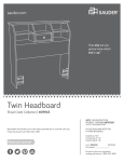
Twin Headboard
Shoal Creek Collection
PLEASE CONTACT US
BEFORE RETURNING
YOUR UNIT TO THE STORE
1-800-523-3987
www.sauder.com
NOTE: THIS INSTRUCTION BOOKLET CONTAINS
IMPORTANT SAFETY INFORMATION.
PLEASE READ AND KEEP FOR FUTURE REFERENCE.
English .................... Page 1-20
Français ...............Pages 21-23
Made in the USA
Archbold, OH
Espanol.............Páginas 24-26
Lot #: 357074
11 / 04 / 13
Date Purchased: ____________________
TABLE OF CONTENTS
ASSEMBLY TOOLS REQUIRED
Part Identification .......................3
No. 2 Phillips Screwdriver
Hardware Identification ......... 4-5
Tip Shown Actual Size
Assembly Steps .................... 6-20
Français .............................. 21-23
Hammer
Espanol............................... 24-26
Warranty ...................................27
Page 2
Electric drill with 1/4" bit
(ONLY in indicated step)
www.sauder.com/services
412091
PART IDENTIFICATION: While not all parts are labeled, some of the parts will have a label or an inked
letter on the edge to help distinguish similar parts from each other. Use this PART IDENTIFICATION to help
identify similar parts.
A
RIGHT END
1
G
SHELF
1
B
LEFT END
1
H
SMALL SHELF
1
C
RIGHT UPRIGHT
1
I
BACK
1
D
LEFT UPRIGHT
1
J
FLIP-UP DOOR
1
E
TOP
1
K
ADJUSTABLE SHELF
2
F
PANEL
1
E
I
D
C
K
H
K
B
J
A
G
F
412091
www.sauder.com/services
Page 3
HARDWARE IDENTIFICATION
L TWIST-LOCK® FASTENER - 4
M2 HIDDEN CAM - 14
N2 CAM DOWEL - 14
O ANGLE BRACKET - 3
P NUT - 4
Q WASHER - 4
R DOOR STOP - 1
S
T
Page 4
RUBBER SLEEVE - 8
METAL PIN - 12
U HINGE SPACER - 2
V HINGE - 2
W KNOB - 1
X HEADBOARD BRACKET - 2
www.sauder.com/services
412091
HARDWARE IDENTIFICATION
Y
SILVER 1-1/4" BOLT - 4
AA SILVER 5/8" FLAT HEAD SCREW - 4
Z
BLACK 1-1/8" MACHINE SCREW - 1
BB
BLACK 9/16" LARGE HEAD SCREW - 14
CC NAIL - 30
Screws are shown actual size. You may receive extra hardware with your unit.
412091
www.sauder.com/services
Page 5
S
p
te
Look for this icon. It means a video
assembly tip is available at:
www.sauder.com/services/tips
1
Do not tighten the TWIST-LOCK® FASTENERS in this step.
L
D
C
Assemble your unit on a carpeted floor or on the empty carton to avoid scratching your unit or the floor.
To begin assembly, push a SAUDER TWIST-LOCK® FASTENER (L) into the large holes in the UPRIGHTS (C and D).
Page 6
www.sauder.com/services
412091
S
p
te
2
Do not tighten the HIDDEN CAMS in this step.
Arrow
N2
(14 used)
M2
G
F
B
A
Arrow
D
C
Insert the metal end of the CAM
DOWEL into the HIDDEN CAM.
Push fourteen HIDDEN CAMS (M2) into the ENDS (A and B), UPRIGHTS (C and D), PANEL (F), and SHELF (G). Then, insert the
metal end of a CAM DOWEL (N2) into each HIDDEN CAM.
412091
www.sauder.com/services
Page 7
S
p
te
3
Angled edge
Finished edge
e
fac
r
u
S
h
wit DEN
D
HI S D
M
CA
B
ith S
w
M
e
fac N CA
r
u
S DE
HID
E
Sur
fac
ew
ith
hol
es
Fasten the LEFT END (B) and LEFT UPRIGHT (D) to the TOP (E). Tighten three HIDDEN CAMS.
Caution
Risk of damage or
injury. Hidden Cams
must be completely
tightened. Hidden
Cams that are not
completely tightened
may loosen, and parts
may separate.
To completely tighten:
Page 8
Start
Arrow
Tighten
Maximum
210 degrees
Arrow
Minimum
190 degrees
www.sauder.com/services
412091
S
p
te
4
Finished edge
D
Sur
f
hol ace w
es ith
H
T
Insert four METAL PINS (T) into the SMALL SHELF (H).
Insert the METAL PINS (T) in one end of the SMALL SHELF (H) into the holes in the LEFT UPRIGHT (D).
412091
www.sauder.com/services
Page 9
S
p
te
5
Angled edge
H
C
E
Maximum
210 degrees
Arrow
Minimum
190 degrees
G
ut S
ho M
it A
w C
ce N
fa E
ur D
S ID
H
R
Fasten the RIGHT UPRIGHT (C) to the TOP (E) and SMALL SHELF (H). Tighten the HIDDEN CAM.
NOTE: Be sure the PINS in the SMALL SHELF (H) insert into the holes in the RIGHT UPRIGHT (C).
With a hammer, tap the DOOR STOP (R) into the small hole in the SHELF (G) as shown in the lower diagram.
Page 10
www.sauder.com/services
412091
S
p
te
6
AA
SILVER 5/8" FLAT HEAD SCREW
(4 used in this step)
V
U
V
J
U
Fasten two HINGE SPACERS (U) and two HINGES (V) to the FLIP-UP DOOR (J). Use four SILVER 5/8" FLAT
HEAD SCREWS (AA).
412091
www.sauder.com/services
Page 11
S
p
te
7
Mounting screw
W
J
H
BLACK 1-1/8" MACHINE SCREW
(1 used in this step)
Z
Fasten the FLIP-UP DOOR (J) to the SMALL SHELF (H). Use the screws in the HINGE. See the next step for adjustments.
NOTE: You may need to loosen the mounting screw to slide it part way out of the slot. Retighten the screw before you mount the
HINGE to the SHELF.
NOTE: The top edge of the DOOR (J) and the top surface of the SMALL SHELF (H) should be even.
Fasten the KNOB (W) to the FLIP-UP DOOR (J). Use the BLACK 1-1/8" MACHINE SCREWS (Z).
Page 12
www.sauder.com/services
412091
S
p
te
8
Adjusting screw (vertical)
(horizontal adjustment)
Mounting screw (depth)
Refer to the enlarged diagram to identify the parts on the HINGES.
The DOORS may need some adjustments. Follow the text below to make needed adjustments.
DOOR ADJUSTMENTS:
To adjust the DOORS up and down (vertical), loosen the mounting screw several turns, then turn the adjusting screw in or out. Tighten
the mounting screw after making adjustments.
To adjust the DOORS side to side (horizontal), loosen both horizontal adjustment screws. Move the DOOR left or right to the desired
location. Tighten the screws after making adjustments.
To adjust the DOORS in or out (depth), loosen the mounting screw one turn and move the DOORS in or out, as needed. Tighten the
mounting screw after making adjustments.
412091
www.sauder.com/services
Page 13
S
p
te
9
How to use the SAUDER TWIST-LOCK® FASTENER
1. Insert the dowel end of the FASTENER into the
hole of the adjoining part.
NOTE: The dowel end of the FASTENER must remain
fully inserted in the hole of the adjoining part while
locking the FASTENER.
2. Tighten the FASTENER with a Phillips screwdriver
as tight as possible.
Dowel end
B
D
C
G
Maximum
210 degrees
Sur
f
HIDace w
DE ith
NC
AM
Rounded edge
S
Arrow
Minimum
190 degrees
Fasten the SHELF (G) to the UPRIGHTS (C and D). Tighten four TWIST-LOCK® FASTENERS.
NOTE: Be sure the CAM DOWELS in the SHELF insert into the holes in the LEFT END (B).
Fasten the SHELF (G) to the LEFT END (B). Tighten two HIDDEN CAMS.
Page 14
www.sauder.com/services
412091
S
p
te
10
F
S
h M
it A
w C
ce N
fa E
ur D
S ID
H
O
BB
BLACK 9/16" LARGE HEAD SCREW
(3 used in this step)
Fasten three ANGLE BRACKETS (O) to the PANEL (F). Use three BLACK 9/16” LARGE HEAD SCREWS (BB).
NOTE: Be sure the edges of the ANGLE BRACKETS are even with the edge of the PANEL.
412091
www.sauder.com/services
Page 15
S
p
te
11
BB
BLACK 9/16" LARGE HEAD SCREW
(3 used in this step)
B
F
Sur
f
HIDace w
DE ith
NC
AM
S
G
E
Maximum
210 degrees
Arrow
Minimum
190 degrees
Carefully stand your unit on its TOP (E).
Fasten the PANEL (F) to the LEFT END (B). Tighten two HIDDEN CAMS.
Fasten the PANEL (F) to the SHELF (G). Use three BLACK 9/16" LARGE HEAD SCREWS (BB) through the ANGLE
BRACKETS and into the SHELF.
Page 16
www.sauder.com/services
412091
S
p
te
12
F
A
G
e
fac
r
u
S out
h
wit DEN
HID S
M
CA
Angled edge
E
Maximum
210 degrees
Arrow
Minimum
190 degrees
Fasten the RIGHT END (A) to the TOP (E), PANEL (F), and SHELF (G). Tighten six HIDDEN CAMS.
412091
www.sauder.com/services
Page 17
S
Caution
Do not stand the unit upright without the
BACK fastened. The unit may collapse.
p
te
13
These holes must line up over
the UPRIGHTS and SHELF.
nfi
U
ed
sh
ni
ce
rfa
su
I
CC
NAIL
(30 used in this step)
Carefully turn your unit over onto its front edges. Unfold the BACK (I) and lay it over your unit.
Make equal margins along all four edges of the BACK (I). Push on opposite corners of your unit if needed to make it “square”.
Fasten the BACK (I) to your unit using the NAILS (CC).
NOTE: Be sure to tap NAILS into the holes that line up over the UPRIGHTS (C and D) and SMALL SHELF (H).
NOTE: Perforations have been provided for access through the BACK. Carefully cut out the holes needed.
Page 18
www.sauder.com/services
412091
S
p
te
14
T
S
(8 used)
5 lbs.
10 lbs.
K
D
5 lbs.
C
K 5 lbs.
If you purchased the 411899
Mates Bed, use the lower four
holes to fasten the HEADBOARD
BRACKETS to the ENDS.
25 lbs. total
B
X
A
X
BB
BLACK 9/16" LARGE HEAD SCREW
(8 used for the HEADBOARD BRACKETS)
Y
SILVER 1-1/4" BOLT
Q
WASHER
P
NUT
(4 of each used in this step)
Carefully stand your unit upright.
Push the RUBBER SLEEVES (S) over the METAL PINS (T). Insert the METAL PINS into the hole locations of your choice in the
ENDS (A and B) and UPRIGHTS (C and D). Set the ADJUSTABLE SHELVES (K) onto the METAL PINS.
Fasten the HEADBOARD BRACKETS (X) to the ENDS (A and B). Use eight BLACK 9/16" LARGE HEAD SCREWS (BB). Use
the holes that are best suited for the height of your bedframe.
NOTE: If you purchased the Mates Bed #411899 go to the next step on how to fasten it to this unit.
Fasten the bedframe to the HEADBOARD BRACKETS (X). Use four SILVER 1-1/4" BOLTS (Y), WASHERS (Q), and NUTS (P).
412091
www.sauder.com/services
Page 19
S
p
te
15
Ma
tes
Be
d#
411
899
Y
SILVER 1-1/4" BOLT
Q
WASHER
P
NUT
(4 of each used in this step)
Finish drilling out four 1/4" holes in the END of the #411899 Mates Bed that will get fastened to the Twin Headboard. Fasten the Mates Bed
to the Twin Headboard with four SILVER 1-1/4" BOLTS (Y), WASHERS (Q), and NUTS (P).
Go to step 17 of the Mates Bed instruction book to complete the assembly of that unit.
This completes assembly. Clean with your favorite furniture polish or a damp cloth. Wipe dry.
Page 20
www.sauder.com/services
412091
412091
Utilisez les instructions d’assemblage en français avec
les schémas étape par étape du manuel d’instruction
en anglais. Chaque étape en français correspond à la
même étape en anglais. La pièce devant être attachée
à l’élément est représentée en gris sur les schémas de
chaque étape pour plus de précision. Comparer la “Liste
de pièces” ci-dessous avec la “PART IDENTIFICATION”
du manuel en anglais pour vous familiariser avec les
pièces avant l’assemblage.
REMARQUE : CE MANUEL D’INSTRUCTIONS
CONTIENT D’IMPORTANTES INFORMATIONS
RELATIVES À LA SÉCURITÉ. À LIRE ET CONSERVER
POUR TOUTE RÉFÉRENCE FUTURE.
Tête de lit, lit de 1 place
NOUS SOMMES LA POUR VOUS AIDER!
Nous faisons de notre mieux pour nous assurer que
votre meuble arrive dans d’excellentes conditions. Nos
représentants du service Clientèle sont aimables et prêts
à vous aider au cas où une pièce aurait été endommagée
ou manquerait (ou si vous aviez besoin d’aide pour
l’assemblage). NE RAMENEZ PAS LE MEUBLE AU
MAGASIN. Au Canada, composez ce numéro d’appel gratuit:
1-800-523-3987
Du lundi au vendredi, de 9 heures du matin à
5:30 heures du soir (horaire Côte Est)
(sauf jours fériés)
Si une pièce a besoin d’être remplacée, la pièce de
remplacement sera envoyée dans les 48 heures. (Sauf
week-ends et jours fériés)
LISTE DE PIÈCES
REFERENCE DESCRIPTION
QUANTITÉ
LISTE DE PIÈCES
REFERENCE DESCRIPTION
QUANTITÉ
A
EXTRÉMITÉ DROITE ......................1
L
FIXATION TWIST-LOCK® ...............4
B
EXTRÉMITÉ GAUCHE ....................1
M2
EXCENTRIQUE ESCAMOTABLE ....14
C
MONTANT DROIT............................1
N2
CHEVILLE D'EXCENTRIQUE .......14
D
MONTANT GAUCHE .......................1
O
CONSOLE À ÉQUERRE .................3
E
DESSUS ..........................................1
P
ÉCROU ............................................4
F
PANNEAU ........................................1
Q
RONDELLE ......................................4
G
TABLETTE .......................................1
R
ARRÊT DE PORTE..........................1
H
PETITE TABLETTE..........................1
S
MANCHON EN CAOUTCHOUC ......8
I
ARRIÈRE .........................................1
T
GOUPILLE EN MÉTAL ..................12
J
PORTE ABATTANTE .......................1
U
K
TABLETTE RÉGLABLE ...................2
RONDELLE D'ESPACEMENT
DE CHARNIÈRE ..............................2
V
CHARNIÈRE ....................................2
W
BOUTON ..........................................1
X
CONSOLE DE TÊTE DE LIT ...........2
Y
BOULON ARGENTÉ 32 mm ............4
Z
VIS À MÉTAUX 28 mm NOIRE ........1
AA
VIS TÊTE PLATE 16 mm ARGENT ....4
BB
VIS TÊTE LARGE 14 mm NOIRE ....14
A l’usage exclusif du
Canada Noter la date
d’achat de cet élément
et conserver le livret
pour future référence.
Pour contacter Sauder
en ce qui concerne cet
élément, faire référence
au numéro de lot et
numéro de modèle en
appelant notre numéro
sans frais.
CC CLOU .............................................30
Lot nº : ____________
Date de
l’achat: ____________
412091
www.sauder.com/services
Page 21
ÉTAPE 1
ÉTAPE 6
REMARQUE : Ne pas serrer les FIXATIONS TWISTLOCK® à ce stade de l'assemblage.
Fixer deux RONDELLES D'ESPACEMENT DE
CHARNIÈRE (U) et deux CHARNIÈRES (V) à la PORTE
ABATTANTE (J). Utiliser quatre VIS TÊTE PLATE
16 mm ARGENTÉES (AA).
Assembler l'élément sur un sol à moquette ou sur le
carton vide pour éviter d'endommager l'élément ou le sol.
Pour commencer l'assemblage, enfoncer une FIXATION
TWIST-LOCK® SAUDER (L) dans les gros trous
des MONTANTS (C et D).
ÉTAPE 2
Ne pas serrer les EXCENTRIQUES ESCAMOTABLES
dans cette étape.
Enfoncer quatorze EXCENTRIQUES ESCAMOTABLES (M2)
dans les EXTRÉMITÉS (A et B), les MONTANTS (C et D), le
PANNEAU (F) et la TABLETTE (G). Ensuite, insérer l'extrémité
en métal de la CHEVILLE D'EXCENTRIQUE (N2) dans
chaque EXCENTRIQUE ESCAMOTABLE.
ÉTAPE 7
Fixer la PORTE ABATTANTE (J) sur la PETITE
TABLETTE (H). Utiliser les vis fournies avec la
CHARNIÈRE. Voir l'étape suivante pour réglages.
REMARQUE : Il est peut-être nécessaire de desserrer
la vis de fixation pour le glisser partiellement hors de la
fente. Resserrer la vis avant de monter la CHARNIÈRE
à la TABLETTE.
REMARQUE : Le chant supérieur de la PORTE (J) et la
surface supérieure de la PETITE TABLETTE (H) doivent
être à fleur.
Fixer le BOUTON (W) à la PORTE ABATTANTE (J).
Utiliser la VIS À MÉTAUX 28 mm NOIRE (Z).
ÉTAPE 3
Fixer l'EXTRÉMITÉ GAUCHE (B) et le MONTANT
GAUCHE (D) au DESSUS (E). Serrer trois
EXCENTRIQUES ESCAMOTABLES.
Attention:
Risque des dégâts ou blessures. Les Excentriques
Escamotables doivent être serrés à bloc. Les
Excentriques Escamotables que ne sont pas serrées
à bloc peuvent desserrer et les pièces peuvent
séparer. Pour serrer à bloc, faire tourner l'excentrique
escamotable de 210 degrés.
ÉTAPE 4
Insérer quatre GOUPILLES EN MÉTAL (T) dans la
PETITE TABLETTE (H).
Insérer les GOUPILLES EN MÉTAL (T) situées sur l'une
extrémité de la PETITE TABLETTE (H) dans les trous du
MONTANT GAUCHE (D).
ÉTAPE 8
Consulter le schéma agrandi pour identifier les pièces
des CHARNIÈRES.
Il faut peut-être ajuster les PORTES. Suivre les
indications ci-dessous pour ajuster.
RÉGLAGES DES PORTES :
Pour ajuster les PORTES vers le haut ou vers le bas
(verticalement), desserrer la vis de fixation de plusieurs
tours, puis visser ou dévisser la vis de réglage. Serrer la
vis de montage après avoir ajusté.
Pour ajuster les PORTES latéralement
(horizontalement), desserrer les deux vis de réglage.
Déplacer la PORTE vers la gauche ou vers la droite vers
l’emplacement désiré. Serrer les vis après avoir ajusté.
Pour ajuster les PORTES vers l'intérieur où vers
l'extérieur (profondeur), desserrer la vis de montage
un tour et déplacer les PORTES vers l'intérieur ou vers
l'extérieur. Serrer la vis de montage après avoir ajusté.
ÉTAPE 5
Fixer le MONTANT DROIT (C) au DESSUS (E) et à la
PETITE TABLETTE (H). Serrer
l’EXCENTRIQUE ESCAMOTABLE.
REMARQUE : S'assurer de bien insérer les
GOUPILLES situées sur la PETITE TABLETTE (H) dans
les trous dans le MONTANT DROIT (C).
À l’aide d’un marteau, enfoncer l’ARRÊT DE PORTE (R)
dans le petit trou de la TABLETTE (G) comme l’indique
le schéma inférieur.
Page 22
www.sauder.com/services
412091
ÉTAPE 9
ÉTAPE 13
Utilisation de la FIXATION TWIST-LOCK® SAUDER
Attention:
1. Insérer l'extrémité filetée de la FIXATION dans le trou
de la pièce attenante.
Ne pas relever l'élément dans sa position verticale avant
d'avoir fixé l’ARRIÈRE. L'élément risque de s'effondrer.
REMARQUE : L'extrémité filetée de la FIXATION doit
rester complètement insérée dans le trou de la pièce
attenante lorsque l'on bloque la FIXATION.
Avec précaution, retourner l'élément sur ses chants
avant. Déplier l'ARRIÈRE (I) et le placer sur l'élément.
2. Bien serrer la FIXATION à l'aide d'un tournevis Phillips.
Fixer la TABLETTE (G) aux MONTANTS (C et D). Serrer
quatre FIXATIONS TWIST-LOCK®.
REMARQUE : S’assurer de bien insérer les CHEVILLE
D'EXCENTRIQUE situées sur le TABLETTE dans les
trous de l'EXTRÉMITÉ GAUCHE (B).
Fixer la TABLETTE (G) à l'EXTRÉMITÉ GAUCHE (B).
Serrer deux EXCENTRIQUES ESCAMOTABLES.
ÉTAPE 10
Veiller à avoir des marges égales le long des quatre
chants de l'ARRIÈRE (I). Si besoin est, enfoncer sur
les coins opposés de l'élément pour s'assurer d'être «
d'équerre ».
Fixer l'ARRIÈRE (I) à l'élément à l'aide des CLOUS (CC).
REMARQUE : S'assurer de bien enfoncer les CLOUS dans
les trous qui sont alignés sur les MONTANTS (C et D) et la
PETITE TABLETTE (H).
REMARQUE : Des lignes perforées ont été prévues
pour accéder facilement à l'ARRIÈRE. Découper avec
précaution les trous nécessaires.
Fixer trois CONSOLES À ÉQUERRE (O) au PANNEAU (F).
Utiliser trois VIS TÊTE LARGE 14 mm NOIRES (BB).
ÉTAPE 14
REMARQUE : S'assurer que les chants des CONSOLES
À ÉQUERRE sont à fleur du chant du PANNEAU.
Relever, avec précaution, l'élément dans sa position verticale.
ÉTAPE 11
Placer, avec précaution, l'élément sur le DESSUS (E).
Fixer le PANNEAU (F) à l'EXTRÉMITÉ GAUCHE (B).
Serrer deux EXCENTRIQUES ESCAMOTABLES.
Fixer le PANNEAU (F) à la TABLETTE (G). Utiliser trois
VIS TÊTE LARGE 14 mm NOIRES (BB) à travers les
CONSOLES À ÉQUERRE et dans le DESSOUS.
ÉTAPE 12
Fixer le EXTRÉMITÉ DROITE (A) au DESSUS (E),
au PANNEAU (F) et à la TABLETTE (G). Serrer six
EXCENTRIQUES ESCAMOTABLES.
Enfoncer les MANCHONS EN CAOUTCHOUC (S) sur les
GOUPILLES EN MÉTAL (T). Insérer les GOUPILLES EN
MÉTAL dans les trous choisis dans les EXTRÉMITÉS (A et B)
et MONTANTS (C et D). Poser les TABLETTES
RÉGLABLES (K) sur les GOUPILLES EN MÉTAL.
Fixer les CONSOLES DE TÊTE DE LIT (X) aux
EXTRÉMITÉS (A et B). Utiliser huit VIS TÊTE LARGE
14 mm NOIRES (BB). Utiliser les trous qui sont le mieux
adaptés pour la hauteur du cadre de lit.
REMARQUE : Si on a fait l’achat du Lit Mates n°
411899, passer à l’étape suivante pour voir comment le
fixer à cette unité.
Fixer le cadre de lit aux CONSOLES DE TÊTE DE LIT (X).
Utiliser quatre BOULONS 32 mm ARGENTÉS (Y),
RONDELLES (Q) et ÉCROUS (P).
ÉTAPE 15
Finir de percer quatre trous de 6 mm dans l’EXTRÉMITÉ
du Lit Mates n° 411899 qui sera fixé à la Tête de lit à
une place. Fixer le Lit Mates à la Tête de lit à une place
à l’aide de quatre BOULONS 32 mm ARGENTÉS (Y),
RONDELLES (Q) et ÉCROUS (P).
Aller à l’étape 17 du livret d’instruction du Lit Mates pour
terminer le montage de cette unité.
Ceci complète l'assemblage. Nettoyer à l’aide d’une
encaustique pour meubles ou d’un chiffon humide. Essuyer.
412091
www.sauder.com/services
Page 23
412091
Use estas instrucciones de ensamblaje en español junto
con las figuras paso-a-paso provistas en el folleto inglés.
Cada paso en español corresponde al mismo paso en
inglés. Se destacan las figuras de cada paso con una
tonalidad oscura para mostrar precisamente cual parte se
debe montar a la unidad. Compare la “Lista de Part” abajo
con la “Part Identification” en el folleto en inglés para
familiarizarse con Las partes de ensamblaje.
NOTA: ESTE FOLLETO DE INSTRUCCIONES
CONTIENE INFORMACIÓN IMPORTANTE SOBRE LA
SEGURIDAD. POR FAVOR LEA Y GUÁRDELO PARA
REFERENCIA EN EL FUTURO.
Cabecera de cama sencilla
ESTAMOS AQUI PARA AYUDAR!
Tratamos de asegurar que su mueble llega en condición
excelente. Nuestros representantes de Servicio al Cliente
son amables y listos para ayudarle con servicio rápido
y eficiente si una parte está defectuosa o ausente (o si
necesita ayuda con el ensamblaje). NO DEVUELVA LA
UNIDAD A LA TIENDA. Llame este número sin cargo:
1-800-523-3987
Lunes a viernes, 9:00 a.m. - 5:30 p.m.
Hora oficial del Este
(excepto días festivos)
Si requiere un repuesto de una parte, será enviado dentro
de 48 horas (excepto los fines de semana y días festivos)
LISTA DE PARTES
ITEM
DESCRIPCIÓN
CANTIDAD
LISTA DE PARTES
ITEM
DESCRIPCIÓN
CANTIDAD
A
EXTREMO DERECHO ....................1
L
SUJETADOR TWIST-LOCK® ..........4
B
EXTREMO IZQUIERDO ..................1
M2
EXCÉNTRICO ESCONDIDO .........14
C
PARAL DERECHO ...........................1
N2
PASADOR DE EXCÉNTRICO .......14
D
PARAL IZQUIERDO .........................1
O
SOPORTE ANGULAR .....................3
E
PANEL SUPERIOR ..........................1
P
TUERCA ..........................................4
F
PANEL..............................................1
Q
ARANDELA ......................................4
G
ESTANTE .........................................1
R
TOPE DE PUERTA ..........................1
H
ESTANTE PEQUEÑO ......................1
S
MANGUITO DE GOMA ....................8
I
DORSO ............................................1
T
ESPIGA DE METAL .......................12
J
PUERTA ABATIBLE HACIA ARRIBA .....1
U
ESPACIADOR DE BISAGRA ...........2
K
ESTANTE AJUSTABLE....................2
V
BISAGRA .........................................2
W
POMO ..............................................1
X
MÉNSULA DE CABECERA .............2
Y
PERNO PLATEADO de 32 mm .......4
Z
TORNILLO NEGRO PARA
METAL de 28 mm ............................1
AA
TORNILLO PLATEADO DE CABEZA
PERDIDA de 16 mm ........................4
BB
TORNILLO NEGRO DE CABEZA
GRANDE de 14 mm .......................14
Anote la fecha de
comprar esta unidad y
guarde el folleto para
su referencia futura.
Si necesita ponerse
en contacto con
Sauder en cuanto a
esta unidad, refiérase
al número de lote y
al número de modelo
cuando llame a nuestro
número gratis.
CC CLAVO ...........................................30
No. Lote: ___________
Fecha
de compra: _________
Page 24
www.sauder.com/services
412091
PASO 1
PASO 6
NOTA: No apriete los SUJETADORES TWIST-LOCK®
por ahora.
Fije dos ESPACIADORES DE BISAGRA (U) y dos
BISAGRAS (V) a la PUERTA ABATIBLE HACIA
ARRIBA (J). Utilice cuatro TORNILLOS PLATEADOS
DE CABEZA PERDIDA de 16 mm (AA).
Ensamble la unidad sobre un piso alfombrado o sobre el
cartón vacío para evitar rayar la unidad o el piso.
Para comenzar el ensamblaje, empuje un SUJETADOR
TWIST-LOCK® SAUDER (L) dentro de los agujeros
grandes de los PARALES (C y D).
PASO 2
No apriete los EXCÉNTRICOS ESCONDIDOS en este paso.
Empuje catorce EXCÉNTRICOS ESCONDIDOS (M2)
dentro de los EXTREMOS (A y B), de los
PARALES (C y D), del PANEL (F) y del
ESTANTE (G). A continuación, inserte el extremo de
metal de un PASADOR DE EXCÉNTRICO (N2) dentro
de cada EXCÉNTRICO ESCONDIDO.
PASO 3
Fije el EXTREMO IZQUIERDO (B) y el PARAL
IZQUIERDO (D) al PANEL SUPERIOR (E). Apriete tres
EXCÉNTRICOS ESCONDIDOS.
Precaución:
Riesgo de daños o heridas. Los Excéntricos Escondidos
deben apretarse completamente. Los Excéntricos
Escondidos que no se aprieten completamente se aflojarán
y las partes pueden separarse. Para apretar completamente,
atornille el excéntrico escondido 210 grados.
PASO 4
Inserte cuatro ESPIGAS DE METAL (T) dentro de
ESTANTE PEQUEÑO (H).
Empuje las ESPIGAS DE METAL (T) sujetadas a un
extremo del ESTANTE PEQUEÑO (H) dentro de los
agujeros del PARAL IZQUIERDO (D).
PASO 5
Fije el PARAL DERECHO (C) al PANEL SUPERIOR (E)
y al ESTANTE PEQUEÑO (H). Apriete el
EXCÉNTRICO ESCONDIDO.
PASO 7
Fije la PUERTA ABATIBLE HACIA ARRIBA (J) al
ESTANTE PEQUEÑO (H). Utilice los tornillos provistos
de las BISAGRAS. Consulte el próximo paso para
los ajustes.
NOTA: Puede ser necesario aflojar el tornillo de montaje
para deslizar parcialmente fuera de la ranura. Vuelva a
apretar el tornillo antes de montar la BISAGRA
al ESTANTE.
NOTA: El borde superior de la PUERTA y la
superficie superior del ESTANTE PEQUEÑO (H)
deben estar parejos.
Fije el POMO (W) a la PUERTA ABATIBLE HACIA
ARRIBA (J). Utilice el TORNILLO NEGRO PARA METAL
de 28 mm (Z).
PASO 8
Consulte el diagrama ampliado para identificar las
piezas de las BISAGRAS.
Las PUERTAS pueden requerir de ajustes. Siga el texto
abajo para hacer los ajustes necesarios.
AJUSTE DE LA PUERTA:
Para ajustar las PUERTAS hacia arriba o hacia abajo
(vertical), afloje el tornillo de montaje varias vueltas y gire
el tornillo de ajuste hacia el interior o hacia el exterior.
Apriete el tornillo de montaje después de hacer los ajustes.
Para ajustar las PUERTAS de un lado al otro
(horizontalmente), afloje los tornillos de ajuste horizontal.
Mueva la PUERTA hacia la izquierda o derecha a la ubicación
deseada. Apriete los tornillos después de hacer los ajustes.
Para ajustar las PUERTAS hacia atrás o hacia adelante
(profundidad), afloje el tornillo de montaje una vuelta y
mueva las PUERTAS hacia el interior o hacia el exterior
según sea necesario. Apriete el tornillo de montaje
después de hacer los ajustes.
NOTA: Asegúrese que las ESPIGAS sujetadas al
ESTANTE PEQUEÑO (H) se inserten dentro de los
agujeros del PARAL DERECHO (C).
Con un martillo, golpee el TOPE DE PUERTA (R) para
que entre en el agujero pequeño del ESTANTE (G),
como se indica en el diagrama inferior.
412091
www.sauder.com/services
Page 25
PASO 9
PASO 13
Cómo utilizar el SUJETADOR TWIST-LOCK® SAUDER
Precaución:
1. Inserte el extremo con cabilla del SUJETADOR dentro
del agujero de la parte adjunta.
No coloque la unidad en posición vertical hasta que se
fije el DORSO. La unidad podría caerse.
NOTA: El extremo con cabilla del SUJETADOR debe
quedarse completamente insertado en el agujero de la
parte adjunta cuando se enclava el SUJETADOR.
Cuidadosamente voltee la unidad para que repose
sobre los bordes delanteros. Desdoble el DORSO (I) y
colóquelo sobre la unidad.
2. Apriete el SUJETADOR lo más apretado posible con
un destornillador Phillips (cruz).
Los márgenes a lo largo de los cuatro bordes del
DORSO (I) deben estar uniformes. Empuje sobre las
esquinas opuestas de la unidad si es requerido para
hacerla "cuadrada."
Fije el ESTANTE (G) a los PARALES (C y D). Apriete
cuatro SUJETADORES TWIST-LOCK®.
NOTA: Asegúrese de insertar las PASADOR DE
EXCÉNTRICO de las ESTANTE dentro de los agujeros
del EXTREMO IZQUIERDO (B).
Fije el ESTANTE (G) al EXTREMO IZQUIERDO (B).
Apriete dos EXCÉNTRICOS ESCONDIDOS
PASO 10
Fije el DORSO (I) a la unidad utilizando los CLAVOS (CC).
NOTA: Asegúrese de clavar ligeramente los CLAVOS
dentro de los agujeros que se alinean sobre los
PARALES (C y D) y el ESTANTE PEQUEÑO (H).
NOTA: Hay perforaciones provistas para el acceso a
través del DORSO. Cuidadosamente corte los
agujeros necesarios.
Fije tres SOPORTES ANGULARES (O) al PANEL (F).
Utilice tres TORNILLOS NEGROS DE CABEZA GRANDE
de 14 mm (BB).
PASO 14
NOTA: Asegúrese que los bordes de los SOPORTES
ANGULARES estén nivelados con el borde del PANEL.
Empuje los MANGUITOS DE GOMA (S) sobre las ESPIGAS
DE METAL (T). Inserte las ESPIGAS DE METAL dentro de
los agujeros al nivel preferido de los
EXTREMOS (A y B) y los PARALES (C y D). Coloque
los ESTANTES AJUSTABLES (K) sobre las ESPIGAS
DE METAL.
PASO 11
Cuidadosamente coloque la unidad para que repose
sobre el PANEL SUPERIOR (E).
Fije el PANEL (F) al EXTREMO IZQUIERDO (B). Apriete
dos EXCÉNTRICOS ESCONDIDOS.
Fije el PANEL (F) al ESTANTE (G). Utilice tres
TORNILLOS NEGROS DE CABEZA GRANDE de
14 mm (BB) a través de los SOPORTES ANGULARES y
en el FONDO.
PASO 12
Fije el EXTREMO DERECHO (A) al PANEL SUPERIOR (E),
al PANEL (F) y al ESTANTE (G). Apriete seis
EXCÉNTRICOS ESCONDIDOS.
Cuidadosamente ponga la unidad en posición vertical.
Fije las MÉNSULAS DE CABECERA DE CAMA (X) a los
EXTREMOS (A y B). Utilice ocho TORNILLOS NEGROS
DE CABEZA GRANDE de 14 mm (BB). Use los agujeros
que mejor se adapten a la altura del marco de la cama.
NOTA: Si usted compró la Cama Nido # 411899 vaya al
siguiente paso para conocer la forma de fijarla a esta unidad.
Fije el marco de la cama a las MÉNSULAS DE CABECERA
DE CAMA (X). Utilice cuatro PERNOS PLATEADOS de
32 mm (Y), ARANDELAS (Q) y TUERCAS (P).
PASO 15
Termine de taladrar los cuatro agujeros de 6 mm en el
EXTREMO de la Cama Nido # 411899, que se fijará a
la cabecera para cama sencilla. Fije la Cama Nido a
la cabecera para cama sencilla con cuatro PERNOS
PLATEADOS de 32 mm (Y), ARANDELAS (Q)
y TUERCAS (P).
Vaya al paso 17 del manual de instrucciones de la Cama
Nido para completar el montaje de esa unidad.
Esto completa el ensamblaje. Limpie con su pulimento
para muebles preferido o un paño húmedo. Seque con
un paño.
Page 26
www.sauder.com/services
412091
5-YEAR LIMITED WARRANTY
1. Sauder Woodworking Co. (Sauder®) provides limited warranty coverage to
the original purchaser of this product for a period of five years from the date
of purchase against defects in materials or workmanship of Sauder furniture
components. As used in this Warranty, “defect” means imperfections in
components which substantially impair the utility of the product. This Warranty
gives you specific legal rights, and you may also have other rights which vary
from state to state.
2. There is no warranty coverage for defects or conditions that result from the
failure to follow product assembly instructions, information or warnings, misuse
or abuse, intentional damage, fire, flood, alteration or modification of the product,
or use of the product in a manner inconsistent with its intended use, nor any
condition resulting from incorrect or inadequate maintenance, cleaning, or care.
There is also no warranty coverage for rented products or any products purchased
“used” or “as is”, at a distress or going-out-of business sale, or from a liquidator.
3. As the exclusive remedy under this Warranty, Sauder will (at its sole
option) repair or replace any defective furniture component. Sauder may
require independent confirmation of the claimed defect and proof of purchase.
Replacement parts will be warranted for only the remaining period of the original
Warranty. SAUDER SHALL HAVE NO LIABILITY for ANY INCIDENTAL
OR CONSEQUENTIAL DAMAGES OF ANY KIND and all such damages
are EXCLUDED FROM THIS WARRANTY, such as loss of use, disassembly,
transportation, labor or damage to property on or near the product. Some states do
not allow the exclusion or limitation of incidental or consequential damages, so
the above limitation or exclusion may not apply to you.
4. This Warranty applies only to warranted defects that first arise and are reported
to Sauder within the warranty coverage period. The Warranty cannot be transferred
to subsequent owners or users of the product, and it shall be immediately void in
the event the product is resold, transferred, leased or rented to any third party or
person other than the original purchaser.
5. THERE ARE NO OTHER WARRANTIES APPLICABLE TO THIS
PRODUCT. Under the laws of certain states, there may be no implied warranties
from Sauder and all implied warranties, INCLUDING ANY IMPLIED
WARRANTY OF MERCHANTABILITY OR FITNESS FOR A PARTICULAR
PURPOSE are disclaimed where allowed by law. TO THE EXTENT ANY
IMPLIED WARRANTIES ARE APPLICABLE, ANY IMPLIED WARRANTIES,
INCLUDING ANY IMPLIED WARRANTY OF MERCHANTABILITY OR
FITNESS FOR A PARTICULAR PURPOSE, ARE LIMITED IN DURATION
TO THE DURATION OF THIS EXPRESS WARRANTY or the minimum period
allowed by law, whichever is shorter. Some states do not allow limitations on how
long an implied Warranty lasts, so the above limitation may not apply to you.
6. For Warranty inquiries or claims, please visit our website www.sauder.com.
You can also contact Sauder at 1-800-523-3987. Sauder may require Warranty
claims to be submitted in writing to Sauder Woodworking Co., 502 Middle Street,
Archbold, OH 43502 USA. Please include your sales receipt or other proof of
purchase and a specific description of the product defect.
GARANTIE LIMITÉE DE 5 ANS
1. Sauder Woodworking Co. (Sauder®) offre une couverture de garantie
limitée à l’acheteur initial du présent produit pendant une période de cinq ans
à compter de la date d’achat contre tout défaut de matériaux ou de fabrication
des composantes de mobilier Sauder. Le mot « défaut », tel qu’il est utilisé sous
les termes de la présente garantie, comprend les imperfections des pièces qui
empêchent substantiellement l’utilisation du produit. La présente garantie vous
donne des droits légaux spécifiques et il est possible que vous ayez des droits
supplémentaires variant d’État en État ou de province en province.
2. La présente garantie ne saurait couvrir les défauts ou conditions qui surviendraient
à la suite du non respect des instructions, informations ou mises en garde de
montage, d’une mauvaise utilisation ou d’un abus, d’un dommage intentionnel,
d’un incendie, d’une inondation, d’une altération ou modification du produit, d’une
utilisation du produit allant à l’encontre de son usage prévu, ni aucune condition
résultant d’une maintenance, d’un nettoyage ou d’un entretien inappropriés ou
inadéquats. De plus, il n’existe aucune garantie pour les produits loués ou tous
les produits achetés « d’occasion » ou « en l’état », dans le cadre d’une vente aux
enchères ou de solde pour cessation de commerce, ou auprès d’un liquidateur.
3. En tant que recours exclusif en vertu de la présente garantie, Sauder réparera
ou remplacera (sur sa seule décision) toute composante de mobilier défectueuse.
Sauder peut exiger une confirmation indépendante du défaut revendiqué ainsi
qu’une preuve d’achat. Les pièces de rechange seront garanties uniquement
pendant la période restante de la garantie originale. SAUDER NE SERA EN
AUCUN CAS RESPONSABLE de TOUT DOMMAGE ACCESSOIRE OU
CONSÉCUTIF DE TOUTE SORTE et lesdits dommages sont EXCLUS DE LA
PRÉSENTE GARANTIE, à savoir perte d’utilisation, démontage, transport, main
d’ceuvre ou dommages matériels sur ou à proximité du produit. Certains États
ou provinces ne permettant pas l’exclusion ou la limite aux responsabilités pour
dommages accidentels ou consécutifs, la limite ou l’exclusion ci-dessus peut ne
pas être applicable.
4. La présente garantie ne s’applique qu’aux défauts garantis qui se produisent
pour la première fois et qui sont signalés à Sauder dans les limites de ouverture
de la garantie. La garantie ne peut pas être transférée à des propriétaires ou
utilisateurs subséquents du produit, et sera immédiatement invalidée dans le cas
où le produit est revendu, transféré, loué sous bail ou loué à une tierce partie ou
personne autre que l’acheteur original.
5. IL N’EXISTE AUCUNE AUTRE GARANTIE EN VIGUEUR POUR LE
PRÉSENT PRODUIT. En vertu des lois de certains États ou provinces, il ne peut y
avoir de garanties implicites de la part de Sauder et toutes les garanties implicites,
Y COMPRIS TOUTE GARANTIE IMPLICITE DE COMMERCIABILITÉ
OU D’ADAPTATION À UN USAGE PARTICULIER sont déclinées partout où
la loi l’autorise. DANS LA MESURE OÙ TOUTE GARANTIE IMPLICITE
EST APPLICABLE, TOUTE GARANTIE IMPLICITE, Y COMPRIS TOUTE
GARANTIE DE COMMERCIABILITÉ OU D’ADAPTATION À UN USAGE
PARTICULIER, EST LIMITÉE À LA DURÉE DE LA PRÉSENTE GARANTIE
EXPRESSE ou à la période minimum autorisée par la loi, la période la plus courte
étant retenue. Certains États ne permettant pas que des limites soient imposées quant à
la durée d’une garantie implicite, la limite ci-dessus peut donc ne pas être applicable.
6. Pour toute question concernant la garantie ou toute demande de réclamation,
consulter le site Web www.sauder.com. Il est également possible de contacter
Sauder en composant le 1-800-523-3987. Sauder peut exiger de soumettre les
demandes de réclamation sous garantie par écrit à Sauder Woodworking Co., 502
Middle Street, Archbold, OH 43502 USA. Veuillez joindre votre ticket de caisse ou
toute autre preuve d’achat ainsi qu’une description spécifique du défaut de produit.
GARANTÍA LIMITADA DE 5 AÑOS
1. Sauder Woodworking Co. (Sauder®) provee cobertura de garantía limitada
al comprador original de este producto por un período de cinco años, a partir de
la fecha de compra, contra defectos en los materiales o de mano de obra en los
componentes de muebles Sauder. Como es utilizado en esta Garantía, “defecto”
significa imperfecciones en los componentes que de manera fundamental afecta
la utilidad del producto. Esta Garantía le permite a usted ciertos derechos legales,
y usted también podría poseer otros derechos adicionales, los cuales varían de
estado a estado.
2. No hay cobertura de garantía para defectos o estados que resulten del
incumplimiento en seguir las instrucciones, la información o las advertencias
sobre el ensamblaje del producto; del uso incorrecto o maltrato, del daño
intencional, incendio, inundación, cambio o modificación del producto; o de
la utilización del producto de manera contradictoria con el uso para el cual fue
fabricado, ni por ningún estado que resulte del mantenimiento, limpieza o cuidado
incorrecto o inadecuado. Tampoco no hay cobertura de garantía para los productos
rentados o para cualesquiera productos comprados “de uso” o “como está”, en una
venta de bienes embargados o en una venta por salirse del negocio, o comprados a
un liquidador.
3. Como un recurso exclusivo bajo esta Garantía, Sauder (sólo a su opción)
reparará o reemplazará cualquier componente defectuoso de mueble. Sauder
puede requerir una confirmación independiente de un defecto reclamado y una
prueba de compra. Las piezas de repuesto serán garantizadas solamente por el
período de tiempo que queda de la Garantía original. SAUDER NO TENDRÁ
RESPONSABILIDAD por NINGÚN DAÑO INCIDENTAL O CONSECUENTE
DE NINGÚN TIPO y todos dichos daños SE EXCLUYEN DE ESTA
GARANTÍA, tales como pérdida de uso, desensamblaje, transportación, trabajo
o daño a la propiedad en o cerca del producto. Algunos estados no permiten la
412091
exclusión o limitación de daños incidentales o consecuentes, en tales instancias la
limitación o exclusión antes mencionada podría no ser aplicable a usted.
4. Esta Garantía sólo es aplicable a defectos garantizados que primeramente surjan
y se informen a Sauder dentro del período de cobertura de garantía. La Garantía
no puede ser transferida a propietarios o usuarios subsiguientes del producto, y
ésta será inmediatamente invalidada en el caso que el producto sea revendido,
transferido, arrendado o rentado a cualquier tercero u otra persona que no sea el
comprador original.
5. NO HAY OTRA GARANTÍA APLICABLE A ESTE PRODUCTO. Bajo
las leyes de ciertos estados, pueden no haber garantías implícitas de Sauder
y se hace renuncia de responsabilidad de todas las garantías implícitas donde
lo permita la ley, INCLUYENDO CUALQUIER GARANTÍA IMPLÍCITA
DE MERCANTIBILIDAD O DE APTITUD PARA UN PROPÓSITO EN
PARTICULAR. EN LA MEDIDA CUALQUIER GARANTÍA IMPLÍCITA ES
APLICABLE, CUALESQUIERA GARANTÍAS IMPLÍCITAS, INCLUYENDO
AQUELLA DE MERCANTIBILIDAD O DE APTITUD PARA UN PROPÓSITO
EN PARTICULAR, SE LIMITAN EN DURACIÓN HASTA LA DURACIÓN
DE ESTA GARANTÍA IMPLÍCITA o hasta el periodo mínimo permitido por la
ley, la que sea más corta. Algunos estados no permiten limitaciones en cuanto a la
duración de una garantía implícita, por eso la limitación arriba citada pueda no ser
aplicable a usted.
6. Para solicitud de información o reclamación de Garantía, por favor, visite
nuestro sitio Web www.sauder.com. Usted también puede contactar a Sauder
llamando al 1-800-523-3987. Sauder puede solicitar que las reclamaciones sean
presentadas por escrito a Sauder Woodworking Co., 502 Middle Street, Archbold,
OH 43502 EE.UU. Por favor incluya su recibo de venta u otra prueba de compra y
una descripción detallada del defecto del producto.
www.sauder.com/services
Page 27
Dear valued customer:
Thank you for your purchase
from the Sauder family
companies. It’s our pleasure
to provide you with an
affordable solution that meets
your furniture and storage
needs. I hope you will enjoy it
for years to come.
I am pleased with this company’s consistent
ability to amaze the customer over time. My
grandfather, Erie Sauder, founded the company
in 1934 and later invented and patented the first
commercially successful ready-to-assemble
table. Since then, our furniture has evolved
to always provide you with top performance,
fashionable styling and uncompromised value.
A privately-held family-run business, Sauder
has been able to hold true to the core values
of innovation, integrity, servanthood and
stewardship on which it was founded. As a
result, we offer unmatched style and function in
a product manufactured with industry-leading
and environmentally responsible materials and
processes. Our Sauder branded product line is
still made in Archbold, Ohio, where it all began.
Certificate of Conformity
The Sauder name on the box ensures that
the item you have purchased is made with
the best quality workmanship and materials.
If you should encounter issues with your
product, please let us know. Our award-winning
customer service crew is ready to help at
800-523-3987 or you can reach us online.
1. This certificate applies to the Sauder Woodworking
Product identified by this Instruction Book.
Again, thank you for being a valued
customer. I invite you to visit our website at
www.sauder.com to see additional furniture
selections, find a dealer near you, or learn more
about the heritage of the Sauder company.
November 2013
4. Date of Manufacture: __________________________
2. This certificate applies to compliance of this
product with the CPSC Ban on Lead-Containing
Paint (16 CFR 1303).
3. This product is manufactured by:
Sauder Woodworking Company
502 Middle Street
Archbold, Ohio 43502
(419) 446-2711
Sincerely,
Kevin J. Sauder
President/CEO
register your new
product online
For immediate service, our website is available
24 hours a day, 7 days a week to order replacement
parts, access assembly tips, register your product,
and view Sauder products. www.sauder.com
Consumer Services in United States and Canada
Mon.-Fri. – 9am-5:30pm ET(except holidays)
1-800-523-3987