1
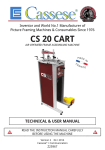
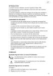
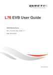
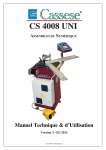
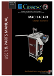
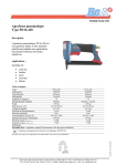
Inventor and World No.1 Manufacturer of Picture Framing Machines & Consumables Since 1976 CS1 UNI FOOT OPERATED UNDERPINNER USER & PARTS MANUAL READ THIS MANUAL CAREFULLY BEFORE USING THE MACHINE Version 2 06/ 2013 Cassese® / Communication Z25389 CS1 UNI FOOT OPERATED UNDERPINNER WORK POSITION REFERENCE 9 6 1st BACK FENCE 1 2nd BACK FENCE 2 HANDLE FOR LOADING WEDGES3 WEDGE DISTRIBUTOR 4 WEDGE POSITION STOP HANDLE (inside of frame) 5 WEDGE POSITION STOP HANDLE (outside of frame) 6 PEDAL 7 MAGNETIC ADJUSTABLE ROD CLAMP ASSEMBLY 8 CROSSBAR9 STAPLING STOP 10 TABLE11 Fig N°1 3 8 5 10 1 2 4 Fig N°2 11 7 AFTER UNPACKING THE MACHINE, SET THE 4 FEET TO LEVEL THE MACHINE Non contractual document - Cassese France® - Document non contractuel CS1 UNI - USER & PARTS MANUAL CONTENTS Page INTRODUCTION 2 ACCESSORIES SUPPLIED WITH THE MACHINE TECHNICAL SPECIFICATIONS OF CS1 UNI OPTIONS GUARANTEE ADJUSTMENTS SELECTION OF WEDGE POSITIONS 3 SETTING AND STORING THE WEDGE POSITIONS PROPER ADJUSTMENT OF MAGNETIC ADJUSTABLE ROD CLAMP ASSEMBLY 3, 4 5 USE MEANS OF JOINING 6 LOADING WEDGES 6 CHANGING SIZE OF WEDGE6 REMOVING WEDGES7 JOINING THE FRAME7 MAINTENANCE LUBRICATION 8 REPLACEMENT OF WEDGE DRIVER 8 REMOVING THE SIDE PANEL9 REMOVING THE WORKING TABLE WITH THE PEDAL REPLACEMENT OF THE WEDGE DISTRIBUTION 0 CHANNEL ELASTIC CORD 1 Non contractual document - Cassese France® - Document non contractuel 9 10 Non contractual document - Cassese France® - Document non contractuel CS1 UNI - USER & PARTS MANUAL INTRODUCTION Thanks for having purchased the CS1 UNI underpinner and for your trust in Cassese products. The CS1 UNI benefits from Cassese’s experience since 1976 in designing and manufacturing highest quality underpinners, for which we are world-famous. The CS1 UNI will allow you to join wooden, plastic and MDF profiles (patent n° 7522814). Joining operation is carried out by using Cassese high-quality metal wedges (Masters™ “UNI”), specially designed to perform perfect and tight frame corners. ACCESSORIES SUPPLIED WITH THE MACHINE A) 1 Magnetic adjustable rod clamp + 1 Locking ring pin + 1 Chevron holder + 1 Magnetic chevron clamp + 1 Chevron rubber. B) 3 stapling heads, each corresponding to a specific size of wedge: 7, 10, 12 mm. C) 1 box of 10mm Hardwood + 1 box of 10mm Softwood. D) 1 wedge-magnet (to assist in removing wedges). E) 1 Allen Key 2.5 mm + 1 Allen Key 3 mm. A Z24703 B Z21525 C 7mm Z25497 10mm Z25498 12mm Z25499 Z6532 Z21524 Z25494 1 box of 10mm HW + 1 box of 10mm SW D Z24322 E Z1879 Z1882 TECHNICAL SPECIFICATIONS OF CS1 UNI Minimum moulding width : 5mm (1/4”) / Minimum moulding height : 7 mm (11/16”) Maximum moulding width : ∞ mm / Maximum moulding height : 100 mm ( 4” ) Maximum stroke between first and last wedge (at 45°) : 140 mm (5 1/2”) Wedge sizes : 5, 7, 10, 12 and 15 mm (5mm wedges can be fired with 7mm stapling head). 3 wedge types : for softwood, hardwood & MDF. Use only Masters™ “UNI” wedges. Machine gross weight : 23 kg (47 lbs) - Dimensions : Width 360mm (14’’) x Depth (w/ out extension table) 610mm (23’’ 3/4) x Height 1200 mm (47’’). OPTIONS (page 20) - Z25500 Stapling head 15 mm - Z1791 Green round clamp - Z1783 Yellow round clamp - Z25510 Stainless steel table extension - Z25147 Stainless steel shelf for wedges and accessories - Z25450 Extension arms - Z22003 Wedge driver. GUARANTEE One year guarantee for parts and labour against manufacturing defects. Wear parts and those damaged as a result of non compliance with the instructions of the present manual are excluded from the guarantee. Loading spring and wedge driver are considered as wear parts. 2 Non contractual document - Cassese France® - Document non contractuel ADJUSTMENTS SELECTION OF WEDGE POSITIONS The CS1 UNI is designed to join mouldings in one, two or more positions without limitation of the number of wedges in any of those places. The selection depends on the width and height of the moulding to join. 2mm MINIMUM 140mm stroke 2mm MINIMUM As a general rule, a MINIMUM 2 mm clearance (less than 1/8”) above the wedges shall be respected. Same size wedges can be stacked in order to avoid changing the size of wedge when joining tall mouldings. AS A GENERAL RULE, THE WEDGE POSITIONS MUST BE SELECTED VERTICALLY TO THE HIGHEST POINTS OF THE MOULDINGS. SETTING AND STORING THE WEDGE POSITIONS Unlock the wedge position stop handles 5 and 6. 6 5 3 Non contractual document - Cassese France® - Document non contractuel Put the first moulding in front of the back fence 1 and slide the moulding in contact with the 2nd back fence 2. 1 Setting up the stapling position close to the outside of the frame : E 6 WEDGE EXIT 2 10 Move forward the sliding table E until the place where you want to insert the wedge(s) has been reached by the WEDGE EXIT (see picture). Then bring the wedge position stop handle 6 against the stapling stop 10 and tighten it. Setting up the stapling position close to the inside of the frame : 1 5 2 10 Move backwards the sliding table E until you have reached the furthest position to the inside of the frame where you want to insert wedge(s). Then bring the wedge position stop handle 5 against the stapling stop 10 and tighten it. Now the two positions of joining are set and the sliding table can move only within the limits of these two positions. 1st position Last position Wedges between the first and the last position 4 Non contractual document - Cassese France® - Document non contractuel PROPER ADJUSTMENT OF MAGNETIC ADJUSTABLE ROD CLAMP ASSEMBLY A magnetic adjustable rod clamp comes with your machine as a standard feature. It fits the crossbar thanks to the locking ring pin and can be set at 1 to 7 positions. You must have 30mm (1 1/4”) max between the clamp and the mouldings. Accessories supplied with the machine Always have the notch (mark) turned to the front of the machine. It helps to avoid any mistakes in the joining of the frame. Magnetic Chevron Clamp HARDWOOD & SOFTWOOD ONE SIZE Green Round Clamp HARDWOOD 30 & 45mm Yellow Round Clamp SOFTWOOD 30 & 45mm Options ACCESSORIES SUPPLIED WITH THE MACHINE: Magnetic chevron clamp is ideal for flat mouldings or for hard to reach surfaces. OPTIONS: The round clamps are dedicated to complicated forms and sloped mouldings. GOOD 2 1 Z24703 BAD 2 1 Pay attention to properly position the magnetic chevron clamp : the sides of the chevron must be parallel to back fences 1 and 2. NEW MAGNETIC ADJUSTABLE CLAMPS OPTIONAL Now with quick-change magnetic clamps, it is easy to change from chevron to a round clamp. Z18065 Z1791 Z21525 5 Non contractual document - Cassese France® - Document non contractuel Z1783 USE MEANS OF JOINING Joining is performed using metal wedges specially designed to ensure perfect corners. Five standard sizes are available: 5, 7, 10, 12 and 15mm (3mm wedges can be fired with 5mm stapling head) for softwood (SW), hardwood (HW) or MDF. For the best corner join, reliability and performance, use only Genuine CASSESE MASTERS™ wedges type “UNI” with your CS1 UNI. LOADING WEDGES Turn handle for loading wedges 3 in direction of arrow in order to bring back wedges pusher. 3 While holding handle in this position, insert strip of wedges into wedges channel. Then gently release the handle for loading wedges 3. CHANGING SIZE OF WEDGES 7 10 12 The CS1 UNI comes with 3 stapling heads, each corresponding to a specific size of wedge, which are 7, 10 & 12mm. The following procedure is to be followed for installing the stapling head on the machine : Using the 2.5mm Allen key provided, unscrew the locking screw of the stapling head located on the machine. Remove the stapling head by pulling it upwards. Insert the stapling head corresponding to the size of wedge chosen and tighten it with the 2.5mm Allen key. Pay attention to install stapling head with the flat side at the top. 6 Non contractual document - Cassese France® - Document non contractuel REMOVING WEDGES First, take the tool Z24322 “wedge-magnet”. Then, put the magnetic end into the wedges to be removed and pull them out after you have pulled the handle for wedges’ loading 3 in the direction of the arrow. JOINING THE FRAME After selecting and setting the wedge positions (page 4 & 5), check the distance between the clamp and the moulding (page 6). Load the required type (softwood, hardwood or MDF) and size of wedges (page 4). 1st step : Put the first moulding in front of the back fence 1 and push it so that its mitre end reaches the other back fence 2. 2nd step : Holding it so, put the second moulding against back fence 2 and slide it until it reaches the first moulding. 3rd step : Holding the mouldings in place against each other, hold the back fences 1 & 2 with your thumbs. Move the sliding table E backwards until the wedge position stop handle 5 reaches the stapling stop 10. 4th step : Keeping the mouldings secure, slowly push down the pedal 7. When the the magnetic adjustable rod clamp assembly 8 will press down on the mouldings, speed up the movement so that the wedge is inserted more easily. 5th step : If there is a second wedge position (with wedge position stop handle 6), just repeat the same operation by moving forward the mouldings and the sliding table E until wedge position stop handle 6 reaches the stapling stop 10 and repeat step 4. NOTE* : If stapling more than one wedge in any position is desired then repeat 4th step. 9 6 7 3 8 5 2 10 E 11 1 4 7 Non contractual document - Cassese France® - Document non contractuel MAINTENANCE CAUTION: WHEN USING COMPRESSED AIR, WEAR SAFETY GLASSES. LUBRICATION STAPLING HEAD Periodically, remove the stapling head and clean it with an air gun. It is recommended to lubricate the wedge driver (use the Cassese’s grease Z1896). To do so, you will have to remove the stapling head with the 2,5mm Allen Key and perform this procedure. REPLACEMENT OF THE WEDGE DRIVER A Unlock the locking screw of the stapling head with the 2.5mm Allen key that is supplied with the machine. Pulling the head up, remove it from the machine. B Inside the machine, using the 2.5mm Allen key, loosen the two locking screws A and B holding the wedge driver. TO SLIDE THE WEDGE DRIVER UP 1st step 2nd step 3rd step Apply some grease on the new wedge driver. Remove excess of grease. Then, follow the step in the order to install the new wedge driver : 3, 2, 1. Under the machine table, tighten back the locking screws A and B with the 2,5mm Allen key. Check the wedge driver installation, it must be able to slide smooth with no resistance. Install back the needed stapling head and lock it using the 2,5mm Allen key. 8 Non contractual document - Cassese France® - Document non contractuel REMOVING THE SIDE PANEL To access more easily to the mechanical parts, you have to remove the side panel where is located the sticker “Cassese France”. The following procedure is to be followed for removing or replacing the side panel of the machine : Unscrew the 4 screws of the working table with the Allen Key 3mm. Next, shift to one side the working table. Take the side panel and remove it by pulling up. Inside view of the CS1 UNI. Now, you can access to the mechanical parts of the machine. REMOVING THE WORKING TABLE WITH THE PEDAL After the previous step, rotate the pedal in its axis and put it in vertical position. You can remove the pedal of its axis by pulling up. Take the working table and the pedal together to exit the mechanical parts from the frame. 9 Non contractual document - Cassese France® - Document non contractuel REPLACEMENT OF THE WEDGE DISTRIBUTION CHANNEL ELASTIC CORD First, you must withdraw the side panel as explained previously. To replace more easily the wedge distribution channel elastic cord, you have to follow these differents steps which will be detailed : First, you must need 2 tools : -Socket spanner 7mm -Allen key 4mm 1. 2. Push away the connection wire in order to free the working space. Unscrew the nut (with the socket spanner 7mm) which maintain the elastic cord and the connection wire. 3. 4. Remove the elastic cord of the screw. Now, the elastic cord is just grasped by the last screw. 5. 6. In order to refit the system, do the following steps in the reverse direction. Unscrew the last screw with the Allen key of 4mm. 10 Non contractual document - Cassese France® - Document non contractuel Non contractual document - Cassese France® - Document non contractuel Inventeur et N°1 Mondial des Machines et Consommables pour l’Encadrement d’Art Depuis 1976 CS1 UNI ASSEMBLEUSE MECANIQUE A PEDALE MANUEL TECHNIQUE & D’UTILISATION AVANT UTILISATION DE LA MACHINE, LIRE IMPERATIVEMENT CE MANUEL D’INSTRUCTIONS Version 2 06/ 2013 Cassese® / Communication Z25389 CS1 UNI ASSEMBLEUSE MECANIQUE A PEDALE REFERENCE POSITION TRAVAIL 8 6 1ère BUTEE1 2ème BUTEE 2 LEVIER DU POUSSOIR D’AGRAFES 3 DISTRIBUTEUR AGRAFES 4 BUTEE POUR POSITION D’AGRAFAGE (intérieur du cadre) 5 BUTEE POUR POSITION D’AGRAFAGE (extérieur du cadre) 6 PEDALE 7 POTENCE DU PRESSEUR8 CHEVRON PRESSEUR 9 BUTOIR10 TABLE11 Fig N°1 3 9 5 10 1 2 4 Fig N°2 11 7 APRES AVOIR DEBALLE LA MACHINE, REGLER LES 4 PIEDS PAR RAPPORT AU SOL Non contractual document - Cassese France® - Document non contractuel CS1 UNI - MANUEL TECHNIQUE & D’UTILISATION SOMMAIRE Page INTRODUCTION 2 ACCESSOIRES FOURNIS AVEC LA MACHINE SPECIFICATIONS TECHNIQUES OPTIONS GARANTIE REGLAGES SELECTION DES POSITIONS D’AGRAFAGE3 3, 4 5 MEMORISATION DES POSITIONS D’AGRAFAGE SELECTION DU PRESSEUR UTILISATION MOYEN D’ASSEMBLAGE 6 CHARGEMENT DES AGRAFES6 CHANGEMENT DE TAILLE D’AGRAFES 6 REMPLACEMENT DES AGRAFES7 ASSEMBLAGE DU CADRE 7 MAINTENANCE LUBRIFICATION 8 REMPLACEMENT DU MARTEAU 8 RETIRER LE PANNEAU LATERAL9 RETIRER LA TABLE DE TRAVAIL AVEC LA PEDALE REMPLACEMENT DU TENDEUR DU DISTRIBUTEUR D’AGRAFES 1 Non contractual document - Cassese France® - Document non contractuel 9 10 Non contractual document - Cassese France® - Document non contractuel CS1 UNI - MANUEL TECHNIQUE & D’UTILISATION INTRODUCTION Vous venez d’acquérir une CS1 UNI. Nous vous félicitons pour votre bon choix et vous remercions pour votre confiance. La CS1 UNI bénéficie de l’expérience des assembleuses qui ont fait la notoriété de Cassese. Elle permet l’assemblage des moulures en bois, plastique et MDF de tous profils (Brevet n° 7522814). L’assemblage est réalisé par des agrafes métalliques (Ref. MASTERS™ “UNI”) spécialement étudiées pour un serrage parfait. ACCESSOIRES FOURNIS AVEC LA MACHINE A) 1 Axe de Presseur Réglable + 1 Broche à Bille + 1 Support Magnétique pour Presseur Chevron + 1 Presseur Chevron + 1 Elastomère chevron. B) 3 têtes de distribution d’agrafes corrélatif à une taille spécifique d’agrafe : 7 ,10 & 12mm. C) 1 boite de 10mm Bois Dur +1 boite de 10mm Bois Tendre. D) 1 tige magnétique (pour enlever les agrafes du couloir de distribution) E) 1 clé Allen de 2,5mm + 1 clé Allen de 3mm A Z24703 B Z21525 7mm Z25497 10mm Z25498 12mm Z25499 Z6532 Z21524 Z25494 C D 1 boite de 10mm Bois Dur + 1 boite de 10mm Bois Tendre Z24322 E Z1879 Z1882 SPECIFICATIONS TECHNIQUES CS1 UNI Largeur minimum profil : 5mm / Hauteur Minimum profil : 5 mm Largeur maximum profil : ∞ mm / Hauteur maximum profil : 100 mm Course d’agrafage maximum entre la 1ère et la dernière agrafe (à 45°) : 140 mm Tailles d’agrafes : 5, 7, 10, 12 et 15 mm (Agrafes 5mm utilisable avec tête d’agrafage de 7mm). 3 types d’agrafes : Bois Normal, Bois Dur ou MDF. N’utiliser que les agrafes Masters™ “UNI”. Poids : 22 kg - Dimensions : 360mm x 610mm (sans table extension) x 1200 mm (hauteur) OPTIONS (cf. p.20) Z25500 Tête distribution agrafe 15 mm - Z1783 Elastomère jaune - Z1791 Elastomère vert Z25510 Rallonge de table - Z25450 Maintien Cadres - Z25147 Support pour barrettes d’agrafes/accessoires - Z22003 Marteau. GARANTIE La CS1 UNI est garantie un an, pièces et main d’oeuvre contre tous vices de fabrication. Les pièces d’usure et celles endommagées par une utilisation non conforme aux dispositions de la présente notice sont exclues de cette garantie . 2 Non contractual document - Cassese France® - Document non contractuel REGLAGES SELECTION DE LA POSITION D’AGRAFAGE La CS1 UNI est prévue pour procéder à l’agrafage des moulures à 1, 2 ou plusieurs endroits sans limitation du nombre d’agrafes à chacun de ces emplacements. Le choix sera fait en fonction de la largeur de la moulure à assembler et de son épaisseur. Il est possible, toutefois, d’insérer des agrafes entre ces deux positions . 2mm MINIMUM 140mm stroke 2mm MINIMUM On prévoit en règle générale une garde, de hauteur 2 mm MINIMUM, au dessus de l’agrafe. Des agrafes de même dimensions peuvent se superposer, ceci pour éviter de changer le chargeur d’agrafes si l’on réalise des assemblages de cadres d’épaisseur diverses. NB : DANS TOUS LES CAS, L’AGRAFAGE DOIT S’EFFECTUER LE PLUS PRES POSSIBLE DE LA (OU DES) PARTIE (S) LA PLUS HAUTE DE LA MOULURE. MÉMORISATION DES POSITIONS D’AGRAFAGES Débloquer les butées de position d’agrafage 5 et 6. 6 5 3 Non contractual document - Cassese France® - Document non contractuel Positionner la 1ère moulure contre la butée 1 et la faire glisser jusqu’à la butée 2. E 6 WEDGE EXIT Première position d’agrafage : Côté extérieur du cadre : Déplacer l’équerre coulissante E vers l’avant jusqu’à la position d’agrafage choisie. Amener la butée 6 contre le butoir 10 et la bloquer. 10 Deuxième position d’agrafage : Côté intérieur du cadre : Déplacer l’équerre coulissante vers l’arrière, jusqu’à la position choisie. Amener la butée 5 en butée contre le butoir 10 et la bloquer. 5 Maintenant, les deux positions d’agrafages sont mémorisées et l’équerre coulissante se déplace uniquement dans la limite de ces deux positions. 10 1ère position Dernière position Agrafes entre la première et la dernière position 4 Non contractual document - Cassese France® - Document non contractuel SELECTION DU PRESSEUR Un presseur est fourni en standard avec son support magnétique. L’axe du presseur se règle en hauteur de 1 à 7 positions grâce à la broche. To u j o u r s avoir le détrompeur tourné vers le devant de la machine. Vous devez avoir 30mm Il permet d’éviter toute erreur maximum entre le presseur dans l’assemblage du cadre. et les moulures. Accessoires fournis avec la machine Options PRESSEUR CHEVRON BOIS DUR & BOIS TENDRE TAILLE UNIQUE ELASTOMERE VERT BOIS DUR 30 & 45mm ELASTOMERE JAUNE BOIS TENDRE 30 & 45mm ACCESSOIRES FOURNIS AVEC LA MACHINE: Le presseur chevron noir est idéal pour l’assemblage de profils plats. OPTIONS : Les presseurs élastomères sont dédiés aux profils à fortes variations géométriques. (montée, descente...) BON 2 1 Z24703 MAUVAIS 2 1 Faire attention à bien positionner le presseur chevron : les côtés du chevron doivent être parallèles aux butées 1 et 2. OPTIONAL NOUVEAUX PRESSEURS MAGNETIQUES Vous pouvez, grâce à leur fonction magnétique, changer rapidement de presseur en fonction des profils à assembler. Z18065 Z1791 Z21525 5 Non contractual document - Cassese France® - Document non contractuel Z1783 UTILISATION LE MOYEN D’ASSEMBLAGE L’assemblage est réalisé par des agrafes métalliques,spécialement étudiées pour un serrage parfait. 5, 7, 10, 12 & 15mm pour l’assemblage de bois NORMAL. 7, 10, 12 & 15mm pour l’assemblage de bois DUR, MDF. Pour une fiabilité et un rendement accrus dans le temps, n’utilisez que des agrafes CASSESE MASTERS™ “UNI” pour votre CS1 UNI. CHARGEMENT DES AGRAFES 3 Actionner le levier 3 afin d’amener le poussoir d’agrafes en arrière. Suivre le sens indiqué par la flèche. Placer la barette d’agrafes. Relâcher le levier 3. CHANGEMENT DE TAILLE D’AGRAFES 7 10 12 La CS1 UNI est livrée avec 3 têtes d’agrafage correspondant chacune à une taille spécifique d’agrafe, soit 7, 10 & 12mm. La mise en place / le remplacement de la tête d’agrafage sur la machine répond strictement à la procédure suivante : Avec la clé Allen de 2,5mm fournie, desserrer la vis de la tête d’agrafage. Retirer le distributeur d’agrafes. Insérer le distributeur d’agrafes correspondant à la taille d’agrafes désirée et resserrer la vis avec la clé Allen de 2,5mm. 6 Non contractual document - Cassese France® - Document non contractuel REMPLACEMENT DES AGRAFES Tout d’abord, vous devez prendre l’outil Z24322 “Ote agrafes”. Ensuite, poser l’extrémité aimantée sur les agrafes à retirer et les retirer après que vous ayez actionné la manette dans le sens de la flèche. ASSEMBLAGE DU CADRE Les points d’agrafage sont mémorisés (voir Mémorisation des points d’agrafage page 3,4 ). La course entre le haut de la moulure et le bas du presseur ne doit pas dépasser pas 30 mm . (Voir Choix du presseur page 5). La bonne taille d’agrafe adaptée au type de matériaux sur la table (bois normal, bois dur, plastique ou MDF) a été chargée dans la CS1 UNI. 1ère étape : Mettre la 1ère moulure sur la table coulissante E, le dos contre 1, la pousser pour atteindre 2 puis la maintenir. 2ème étape : Mettre la 2nde moulure sur la table le dos contre 2 et la pousser en appui jusqu’à la 1ère moulure. 3ème étape : Maintenir 1 et 2 avec les moulures en position d’agrafages 1 (voir photos) contre le butoir 10. 4ème étape : Toujours en maintenant les moulures, enfoncez lentement la pédale 7. Au moment où le presseur vertical 9 entre en contact avec la moulure, accélérez le mouvement de manière à faciliter l’insertion de l’agrafe. Pour superposer les agrafes*, -Relâcher la pédale 7 jusqu’à ce que le presseur vertical 9 commence à se soulever puis enfoncez la de nouveau. *En cas d’empilage, il est recommandé de bloquer la table coulissante E. 5ème étape : Il suffit de déplacer l’ensemble moulures + 1 & 2 en position d’agrafage 2, puis répéter l’étape 4. 8 6 7 3 9 5 2 10 E 11 1 4 7 Non contractual document - Cassese France® - Document non contractuel MAINTENANCE LUBRIFICATION TÊTE D’AGRAFAGE Périodiquement, retirer la tête d’agrafage et la nettoyer à l’air comprimé. Il est recommandé de graisser le marteau périodiquement (utiliser la graisse Cassese Z1896). Pour se faire, démonter la tête d’agrafage avec la clé Allen de 2,5mm fournie et suivre les instructions : ATTENTION : LORS DE L’UTILISATION DE L’AIR COMPRIME, LE PORT DE LUNETTES DE PROTECTION EST OBLIGATOIRE. REMPLACEMENT DU MARTEAU A Desserrer la vis de la tête d’agrafage avec la clé de 2,5mm fournie avec la machine et sortir la tête d’agrafage. B Sous la table de la machine et en utilisant la clé Allen de 2,5mm, desserrer les vis A et B fixant le marteau. FAIRE COULISSER LE MARTEAU VERS LE HAUT 1ère étape 2ème étape 3ème étape Appliquer de la graisse sur le nouveau marteau. Insérer le dans la machine comme indiqué. Enlever les excès de graisse. Suivre les étapes dans l’ordre : 3, 2, 1. Sous la table de la machine, resserer les deux vis A et B avec la clé Allen de 2,5mm. Vérifier la bonne mise en place du marteau. Sa course ne doit pas rencontrer de point dur. 8 Non contractual document - Cassese France® - Document non contractuel RETIRER LE PANNEAU LATERAL Pour accéder plus facilement aux pièces mécaniques, vous devez enlever le panneau latéral où est l’étiquette “Cassese France”. La procédure suivante doit être suivie pour retirer ou remplacer le panneau latéral de la machine : Dévisser les 4 vis de la table de travail avec la clé Allen 3mm. Ensuite, déplacer sur le côté légèrement la table de travail. Maintenant, vous pouvez accéder aux parties mécaniques de la machine. Prenez le panneau latéral et retirez-le de son emplacement. Vue intérieure de la CS 1 UNI. RETIRER LA TABLE DE TRAVAIL AVEC LA PEDALE Après l’étape précédente, faire pivoter la pédale dans son axe pour la mettre en position verticale. Maintenant, Vous pouvez retirer la pédale de son axe en la tirant vers le haut. Prenez la table de travail et la pédale ensemble pour sortir toutes les pièces mécaniques du bati. 9 Non contractual document - Cassese France® - Document non contractuel REMPLACEMENT DU TENDEUR DU DISTRIBUTEUR D’AGRAFES Pour remplacer plus facilement le tendeur du distributeur d’agrafes, vous devez suivre ces étapes différentes qui seront détaillés: Tout d’abord, vous devez prendre 2 outils: -Clé à pipe 7mm -Clé Allen 4mm 1. 2. Déplacer le fil de liaison afin de libérer l’espace de travail. Dévisser l’écrou (avec le clé à pipe) qui maintient ensemble le tendeur et le fil de liaison. 3. 4. Retirer le tendeur de la vis. 5. Maintenant, le tendeur est simplement tenu par la dernière vis. 6. Afin de remettre en place le système, effectuez les étapes précédentes dans le sens inverse. Dévissez la dernière vis avec la clé Allen de 4 mm. 10 Non contractual document - Cassese France® - Document non contractuel NOMENCLATURE / SPARE PARTS - CS1 UNI 11 Non contractual document - Cassese France® - Document non contractuel NOMENCLATURE / CLASSIFICATION CS1 UNI 12 Non contractual document - Cassese France® - Document non contractuel 13 Non contractual document - Cassese France® - Document non contractuel 14 Non contractual document - Cassese France® - Document non contractuel 15 Non contractual document - Cassese France® - Document non contractuel 16 Non contractual document - Cassese France® - Document non contractuel 17 Non contractual document - Cassese France® - Document non contractuel CHANGE OF WORK POSITION CHANGEMENT DE LA POSITION DE TRAVAIL 1. Take the 3mm Allen key for the table’s screws. Prendre la Clé Allen de 3mm pour les vis de la table. 2. 3. 4. 5. 6. 180° 18 Non contractual document - Cassese France® - Document non contractuel 7. 8. AVANT / BEFORE APRES / AFTER 19 Non contractual document - Cassese France® - Document non contractuel INSTALLATION OF THE TABLE EXTENSION (OPTIONAL) / INSTALLATION DE LA RALLONGE DE TABLE (OPTIONNEL) 1. Insert the nut into the slot of the rail. 3. Rotate the nuts in the right direction. 2. Insert the second nut. 1. Insérer l’écrou dans la fente du rail. 3. Insérer le deuxième écrou. 4. Ensure that you have this rendering. 5. Place the nuts on each side of the rail. 4. Assurer vous d’avoir ce rendu. 5. Placer les écrous chaque côté du rail. 7. Be careful to keep the same space between each side of the table to avoid rubbing. de 3. Faire pivoter les écrous dans le bon sens. 6. With the help of the Allen key, put each nut in front of the pathway of the screw. 6. A l’aide de la clé, mettre chaque écrou devant le passage de la vis. 8. Put the table extension at the same level of the working table of your CS1 UNI. 7. Veillez à garder le même espace entre chaque côté de la table pour éviter les frottements. 20 8. Mettez la rallonge de table au même niveau de la table de travail de votre CS1 UNI. Non contractual document - Cassese France® - Document non contractuel OPTIONAL ACCESSORIES ON THE CS1 UNI ACCESSOIRES OPTIONNELS SUR LA CS1 UNI Z22027 Z22027 Z25147 Z25147 21 Non contractual document - Cassese France® - Document non contractuel OPTIONAL ACCESSORIES ON THE CS1 UNI ACCESSOIRES OPTIONNELS SUR LA CS1 UNI Z25450 Z25450 1 15mm Z25500 Z22003 22 Non contractual document - Cassese France® - Document non contractuel ADDRESS Zone Industrielle 77390 VERNEUIL L’ETANG - FRANCE Tel: +33 (0)1 64 42 49 61 / Fax: +33 (0)1 64 42 58 90 E-mail: [email protected] EXPORT DEPARTMENT Tel: +33 (0)1 64 42 49 71 Fax: +33 (0)1 55 02 16 60 +33 (0)1 64 42 49 73 +33 (0)1 55 02 29 48 Website: www.cassese.com /// E-mail: [email protected] SERVICE APRES-VENTE / AFTER SALES DEPARTMENT / KUNDENDIENST DIENST / SERVICIO TECNICO Tel: +33 (0)1 64 06 24 51 Fax: +33 (0)1 55 02 16 64 [email protected]