1
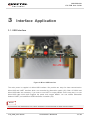
L76 EVB User Guide
GNSS Module Series
Rev. L76_EVB_User_Guide_V1.1
Date: 2013-04-02
www.quectel.com
GNSS Module
L76 EVB User Guide
Our aim is to provide customers with timely and comprehensive service. For any
assistance, please contact our company headquarter:
Quectel Wireless Solutions Co., Ltd.
Room 501, Building 13, No.99, Tianzhou Road, Shanghai, China, 200233
Tel: +86 21 5108 6236
Mail: [email protected]
l
e
t
l
c
a
e
i
t
u
n
Q ide
f
n
o
C
Or our local office, for more information, please visit:
http://www.quectel.com/quectel_sales_office.html
For technical support, to report documentation errors, please visit:
http://www.quectel.com/tecsupport.aspx
GENERAL NOTES
QUECTEL OFFERS THIS INFORMATION AS A SERVICE TO ITS CUSTOMERS. THE INFORMATION
PROVIDED IS BASED UPON CUSTOMERS‟ REQUIREMENTS. QUECTEL MAKES EVERY EFFORT
TO ENSURE THE QUALITY OF THE INFORMATION IT MAKES AVAILABLE. QUECTEL DOES NOT
MAKE ANY WARRANTY AS TO THE INFORMATION CONTAINED HEREIN, AND DOES NOT ACCEPT
ANY LIABILITY FOR ANY INJURY, LOSS OR DAMAGE OF ANY KIND INCURRED BY USE OF OR
RELIANCE UPON THE INFORMATION. ALL INFORMATION SUPPLIED HEREIN ARE SUBJECT TO
CHANGE WITHOUT PRIOR NOTICE.
COPYRIGHT
THIS INFORMATION CONTAINED HERE IS PROPRIETARY TECHNICAL INFORMATION OF
QUECTEL CO., LTD. TRANSMITTABLE, REPRODUCTION, DISSEMINATION AND EDITING OF THIS
DOCUMENT AS WELL AS UTILIZATION OF THIS CONTENTS ARE FORBIDDEN WITHOUT
PERMISSION. OFFENDERS WILL BE HELD LIABLE FOR PAYMENT OF DAMAGES. ALL RIGHTS
ARE RESERVED IN THE EVENT OF A PATENT GRANT OR REGISTRATION OF A UTILITY MODEL
OR DESIGN.
Copyright © Quectel Wireless Solutions Co., Ltd. 2013. All rights reserved.
L76_EVB_User Guide
Confidential / Released
1 / 25
GNSS Module
L76 EVB User Guide
About the document
History
Revision
1.0
1.1
l
e
t
l
c
a
e
i
t
u
n
Q ide
f
n
o
C
Date
Author
Description
2013-02-25
Dishon ZHOU
Initial
2013-03-26
Dishon ZHOU
Optimized the contents of Chapter 3.
L76_EVB_User Guide
Confidential / Released
2 / 25
GNSS Module
L76 EVB User Guide
Contents
About the document ................................................................................................................................... 2
Contents ....................................................................................................................................................... 3
Table Index ................................................................................................................................................... 4
Figure Index ................................................................................................................................................. 5
1
Introduction .......................................................................................................................................... 6
2
Introduction to EVB Kit ....................................................................................................................... 7
2.1. EVB Top and Bottom View .......................................................................................................... 7
2.2. EVB Accessories ......................................................................................................................... 8
3
Interface Application ......................................................................................................................... 10
3.1. USB Interface ............................................................................................................................ 10
3.2. UART Interface.......................................................................................................................... 11
3.3. Antenna Interface ...................................................................................................................... 12
3.4. Switches and Buttons ............................................................................................................... 13
3.5. Operating Status LEDs ............................................................................................................. 14
3.6. Test Points ................................................................................................................................. 15
4
EVB and Accessories ........................................................................................................................ 17
5
Install Device Driver........................................................................................................................... 18
6
Starting PowerGPS ............................................................................................................................ 19
7
Appendix A Reference....................................................................................................................... 25
l
e
t
l
c
a
e
i
t
u
n
Q ide
f
n
o
C
L76_EVB_User Guide
Confidential / Released
3 / 25
GNSS Module
L76 EVB User Guide
Table Index
TABLE 1: PINS OF UART PORT ....................................................................................................................... 11
TABLE 2: SWITCHES AND BUTTONS ............................................................................................................. 13
TABLE 3: OPERATING STATUS LEDS ............................................................................................................ 14
TABLE 4: PINS OF J106 ................................................................................................................................... 15
TABLE 5: EXPLANATIONS OF POWERGPS WINDOW .................................................................................. 20
TABLE 6: REFERENCE .................................................................................................................................... 25
l
e
t
l
c
a
e
i
t
u
n
Q ide
f
n
o
C
TABLE 7: ABBREVIATIONS .............................................................................................................................. 25
L76_EVB_User Guide
Confidential / Released
4 / 25
GNSS Module
L76 EVB User Guide
Figure Index
FIGURE 1: EVB TOP VIEW ................................................................................................................................ 7
FIGURE 2: EVB BOTTOM VIEW ........................................................................................................................ 8
FIGURE 3: EVB ACCESSORIES ........................................................................................................................ 9
FIGURE 4: MICRO-USB INTERFACE .............................................................................................................. 10
FIGURE 5: UART INTERFACE .......................................................................................................................... 11
FIGURE 6: ANTENNA INTERFACE .................................................................................................................. 12
l
e
t
l
c
a
e
i
t
u
n
Q ide
f
n
o
C
FIGURE 7: LNA LAYOUT .................................................................................................................................. 12
FIGURE 8: SWITCHES AND BUTTONS .......................................................................................................... 13
FIGURE 9: OPERATING STATUS LEDS .......................................................................................................... 14
FIGURE 10: TEST POINTS J106 ...................................................................................................................... 15
FIGURE 11: EVB AND ACCESSORY EQUIPMENTS ...................................................................................... 17
FIGURE 12: POWERGPS TOOL ...................................................................................................................... 19
FIGURE 13: MTK COMMAND .......................................................................................................................... 21
FIGURE 14: STATIC TTFF TESTING ............................................................................................................... 22
FIGURE 15: STATIC TTFF TESTING CONFIGURATION OPTIONS ............................................................... 23
FIGURE 16: STATIC TTFF TESTING CONFIGURATION ................................................................................ 24
L76_EVB_User Guide
Confidential / Released
5 / 25
GNSS Module
L76 EVB User Guide
1
Introduction
This document defines and specifies the usage of L76 EVB (Evaluation Board). You can get useful
information about L76 EVB and GNSS demo tool from this document.
l
e
t
l
c
a
e
i
t
u
n
Q ide
f
n
o
C
L76_EVB_User Guide
Confidential / Released
6 / 25
GNSS Module
L76 EVB User Guide
2
Introduction to EVB Kit
2.1. EVB Top and Bottom View
l
e
t
l
c
a
e
i
t
u
n
Q ide
f
n
o
C
Figure 1: EVB Top View
L76_EVB_User Guide
Confidential / Released
7 / 25
GNSS Module
L76 EVB User Guide
l
e
t
l
c
a
e
i
t
u
n
Q ide
f
n
o
C
Figure 2: EVB Bottom View
A:
B:
C:
D:
E:
F:
G:
H:
I:
J:
K:
UART port
Serial port alternation switch
RESET button
FORCE_ON button
POWER switch
Micro-USB port
Indication LEDs
Antenna interface
L76 Module
STANDBY switch
Test points
2.2. EVB Accessories
L76_EVB_User Guide
Confidential / Released
8 / 25
GNSS Module
L76 EVB User Guide
l
e
t
l
c
a
e
i
t
u
n
Q ide
f
n
o
C
Figure 3: EVB Accessories
A:
B:
USB cable
GNSS active antenna (3.3V)
L76_EVB_User Guide
Confidential / Released
9 / 25
GNSS Module
L76 EVB User Guide
3
Interface Application
3.1. USB Interface
l
e
t
l
c
a
e
i
t
u
n
Q ide
f
n
o
C
Figure 4: Micro-USB Interface
The main power is supplied via Micro-USB interface. We provide two ways for data communication:
Micro-USB and UART interface which are controlled by alternation switch (S2). Both of RS232 and
Micro-USB cable are necessary, if you want to use UART to output NEMA. So the easy way is to use
Micro-USB cable which both supplies the power and outputs NEMA. You can makes alternation
between UART port and Micro-USB interfaces via switch (S2).
NOTE
If you want to use PowerGPS Tool, UART interface is recommended for data communication.
L76_EVB_User Guide
Confidential / Released
10 / 25
GNSS Module
L76 EVB User Guide
3.2. UART Interface
l
e
t
l
c
a
e
i
t
u
n
Q ide
f
n
o
C
Figure 5: UART Interface
Table 1: Pins of UART port
Pin
2
3
5
Signal
I/O
Description
RXD
I
Receive data
TXD
O
Transmit data
GND
L76_EVB_User Guide
GND
Confidential / Released
11 / 25
GNSS Module
L76 EVB User Guide
3.3. Antenna Interface
l
e
t
l
c
a
e
i
t
u
n
Q ide
f
n
o
C
Figure 6: Antenna Interface
Figure 7: LNA Layout
L76_EVB_User Guide
Confidential / Released
12 / 25
GNSS Module
L76 EVB User Guide
For choice of external antenna, both of active antenna and passive antenna can be selected. Please note
the LNA is installed in the EVB by default, so you have to move C109 to R112 and R118 to R105, when
you want to remove the LNA for test.
3.4. Switches and Buttons
l
e
t
l
c
a
e
i
t
u
n
Q ide
f
n
o
C
Figure 8: Switches and Buttons
Table 2: Switches and Buttons
Part
Name
I/O
Description
S1
POWER
I
Control power supply via Micro-USB.
S2
Serial
port
alternation switch
I
QUECTEL EVB supplies two communicative
ways: Micro-USB and UART which are controlled
by switch.
S3
STANDBY
I
The module will enter into standby mode when
switching from OFF to ON, and exit from standby
L76_EVB_User Guide
Confidential / Released
13 / 25
GNSS Module
L76 EVB User Guide
mode in the opposite operation.
K1
FORCE_ON
I
Press and release the button, the module will be
waked up from backup mode.
K2
RESET
I
Press and release this button, then the module
will reset.
3.5. Operating Status LEDs
l
e
t
l
c
a
e
i
t
u
n
Q ide
f
n
o
C
Figure 9: Operating Status LEDs
Table 3: Operating status LEDs
Part
Name
I/O
Description
L1
TXD1
O
Flash: turn on successfully, Micro-USB or UART1
port can output messages.
Extinct: fail to turn on the module.
L2
1PPS
O
Flash: fix successfully, the frequency is 1Hz.
Extinct: no fix.
L76_EVB_User Guide
Confidential / Released
14 / 25
GNSS Module
L76 EVB User Guide
3.6. Test Points
l
e
t
l
c
a
e
i
t
u
n
Q ide
f
n
o
C
Figure 10: Test Points J106
Table 4: Pins of J106
Pin
Signal
1
32K/DRIN
2
AADET_N
I
Active antenna open circuit detection
3
1PPS
O
1 pulse per second
4
STANDBY
I
Enter or exit standby mode
L76_EVB_User Guide
I/O
Description
Reserved
Confidential / Released
15 / 25
GNSS Module
L76 EVB User Guide
5/10
GND
Ground
6
FORCE_ON
Logic high will force module to be waked
up from backup mode. Keep this pin open
or pulled low before entering into backup
mode. If unused, keep this pin open.
7
RESET
I
System reset
8
TXD1
O
Transmit data
9
l
e
t
l
c
a
e
i
t
u
n
Q ide
f
n
o
C
RXD1
L76_EVB_User Guide
I
Receive data
Confidential / Released
16 / 25
GNSS Module
L76 EVB User Guide
4
EVB and Accessories
The EVB and its accessories are equipped as shown in Figure 11.
l
e
t
l
c
a
e
i
t
u
n
Q ide
f
n
o
C
Figure 11: EVB and Accessory Equipments
L76_EVB_User Guide
Confidential / Released
17 / 25
GNSS Module
L76 EVB User Guide
5
Install Device Driver
Please note that you need to install the driver of Micro-USB, when use Micro-USB for data communication.
The driver has been stored in our FTP server. The driver of CP210x also can be download from internet.
The download path of our FTP server is as below:
l
e
t
l
c
a
e
i
t
u
n
Q ide
f
n
o
C
Overseas customer: /d:/FTP/OC/Overseas_Technical/Overseas_Module Official Documents/GNSS
Module/Common/04 Tool Kit/ GNSS_EVB_Micro-USB_Driver_CP210x.
Domestic customer: /d:/FTP/CC/Domestic_Technical/Domestic_Module Official Documents/GNSS
Module/Common/04 Tool Kit/ GNSS_EVB_Micro-USB_Driver_CP210x.
L76_EVB_User Guide
Confidential / Released
18 / 25
GNSS Module
L76 EVB User Guide
6
Starting PowerGPS
The PowerGPS version is V2.2.0. The PowerGPS tool can help user to view the status of
GPS&GLONASS receiver conveniently. When the tool is opened, the following window will be displayed:
l
e
t
l
c
a
e
i
t
u
n
Q ide
f
n
o
C
Figure 12: PowerGPS Tool
After EVB accessories are assembled, turn on the module and start up the PowerGPS. Select a correct
COM port and baud rate (L76 module supports 9600bps by default), then click the button “Create
Connection”.
From the PowerGPS window, user can view CNR message, time, position, speed, precision and so on.
Explanations are listed in Table 5.
L76_EVB_User Guide
Confidential / Released
19 / 25
GNSS Module
L76 EVB User Guide
Table 5: Explanations of PowerGPS Window
Icon
Explanation
SV with PRN 65. If the position of SV is near to the centre of the
Sky View, the elevation angle of SV is close to 90°. Dark blue
means this satellite is in tracking.
Light blue means this satellite is not in tracking.
l
e
t
l
c
a
e
i
t
u
n
Q ide
f
n
o
C
The CNR of PRN 25 is 31dB/Hz. Light blue column means the
navigation data of this satellite is in use.
The CNR of PRN 70 is 32dB/Hz. White column means the
navigation data of this satellite is not in use. The range of
GLONASS SVID is 65-96.
UTC time
Latitude degree
longitude degree
Positing fix
Using the number of satellites
Horizontal Dilution of Precision
Altitude based on WGS84 Datum
UTC date
Fix type: No-Fix, 3D or 2D SPS
Using satellite
Position Dilution of Precision
Vertical Dilution of Precision
Speed of receiver
L76_EVB_User Guide
Confidential / Released
20 / 25
GNSS Module
L76 EVB User Guide
PMTK Command
You can send PMTK command by PowerGPS. The format of PMTK command includes only characters
between „$‟ and „*‟, for example: PMTK869,0.
l
e
t
l
c
a
e
i
t
u
n
Q ide
f
n
o
C
Figure 13: MTK Command
Automatic TTFF Testing
This tool allows you to measure the TTFF (Time to First Fix) under different testing conditions. You can
choose to test the TTFF from full start, cold start, warm start and hot start and the number of tests can be
chosen from 1, 10, 20, 100, 1000 and 10000. Click on the Run button to start the test and it can be
stopped by clicking on the Stop button. The configuration is as below:
Start “MTK” menu, and click “Static TTFF Testing”, then “Static TTFF Testing” as shown below:
L76_EVB_User Guide
Confidential / Released
21 / 25
GNSS Module
L76 EVB User Guide
l
e
t
l
c
a
e
i
t
u
n
Q ide
f
n
o
C
Figure 14: Static TTFF Testing
Click “Set reference point”, choose “Reference location”. After start positioning, click “Use Mean Position”,
then click “OK”. As shown in the screenshots below:
L76_EVB_User Guide
Confidential / Released
22 / 25
GNSS Module
L76 EVB User Guide
l
e
t
l
c
a
e
i
t
u
n
Q ide
f
n
o
C
Figure 15: Static TTFF Testing Configuration Options
Click “Config”, set “TTFF Time- out (sec)”, then click “OK”, shown as below:
In generally, if you choose hot start, “TTFF Time-out (sec)” sets 10s. If you choose warm start, the “TTFF
Time-out (sec)” sets 50s. If you choose cold start, the “TTFF Time-out (sec)” sets 100s. “TTFF Time–out
(sec)” can help you judge TTFF and save time.
L76_EVB_User Guide
Confidential / Released
23 / 25
GNSS Module
L76 EVB User Guide
l
e
t
l
c
a
e
i
t
u
n
Q ide
f
n
o
C
Figure 16: Static TTFF Testing Configuration
The above operation is completed. Click on the Run button to start the test and it can be stopped by
clicking Stop button.
After finishing the testing, you can see the testing result charts. Of course, the result also will be stored in
the tool installation path, and you can view the corresponding log.
L76_EVB_User Guide
Confidential / Released
24 / 25
GNSS Module
L76 EVB User Guide
7
Appendix A Reference
Table 6: Reference
SN
[1]
[2]
[3]
l
e
t
l
c
a
e
i
t
u
n
Q ide
f
n
o
C
Document name
Remark
L76_Hardware_Design
L76 Hardware Design
L76_Protocol_Specification
L76 Protocol Specification
L76_Reference Design
L76 Reference Design
Table 7: Abbreviations
Abbreviation
Description
CNR
Carrier-to-Noise Ratio
GPS
GLONASS
GNSS
LED
PPS
PRN
Global Positioning System
Global Navigation Satellite System (The Russian GNSS)
Global Navigation Satellite System
Light Emitting Diode
Pulse Per Second
Pseudorandom Noise
SPS
Standard Positioning Service
SV
Satellite Vehicle
UART
Universal Asynchronous Receiver & Transmitter
UTC
Universal Time Coordinated
WGS84
World Geodetic System 1984
L76_EVB_User Guide
Confidential / Released
25 / 25